
AJPD900W User Guide
Page 4
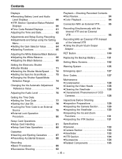
... External VTR 96 Recording With an External VTR Instead of the Internal VTR ¡Using the 26-pin/12-pin Output Adaptor 98 Adjusting the White Balance/Black Balance RET Button 100 ¡Adjusting the White Balance 66 ¡Adjusting the Black Balance 69 Setting the Electronic Shutter ¡Shutter Modes 71 ¡Selecting the Shutter Mode/Speed . . . 72 Replacing the Backup Battery 101 Setting Menu Screens 102 Warning System 125 Emergency eject 127 ¡Setting the Synchro Scan Mode . . . . . 73 ¡Changing the Shutter Speed/Mode...
... External VTR 96 Recording With an External VTR Instead of the Internal VTR ¡Using the 26-pin/12-pin Output Adaptor 98 Adjusting the White Balance/Black Balance RET Button 100 ¡Adjusting the White Balance 66 ¡Adjusting the Black Balance 69 Setting the Electronic Shutter ¡Shutter Modes 71 ¡Selecting the Shutter Mode/Speed . . . 72 Replacing the Backup Battery 101 Setting Menu Screens 102 Warning System 125 Emergency eject 127 ¡Setting the Synchro Scan Mode . . . . . 73 ¡Changing the Shutter Speed/Mode...
AJPD900W User Guide
Page 5
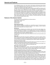
... be set , black balance and white balance can also be automatically adjusted by a 36 MHz (typ.) 10-bit AD/DA converter. Setup cards Setting menu and subject data can be stored on . The high S/N ratio allows images with low power consumption, and realizes the optimal functions and performance for an electronic news gathering (ENG) VTR-integrated camera such as the display conditions when items are recorded onto...
... be set , black balance and white balance can also be automatically adjusted by a 36 MHz (typ.) 10-bit AD/DA converter. Setup cards Setting menu and subject data can be stored on . The high S/N ratio allows images with low power consumption, and realizes the optimal functions and performance for an electronic news gathering (ENG) VTR-integrated camera such as the display conditions when items are recorded onto...
AJPD900W User Guide
Page 6
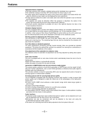
... screen. Four filter disks as standard equipment CC (color temperature conversion) and ND (neutral density) filters are provided as the unit's power supply, the remaining battery level can be finely adjusted by setting menu operations. When the eyepiece is equipped with various warning lamps and a warning tone. In addition, when using the AJ-MH700P microphone holder (option). ¡The audio CH1 recording level can be checked...
... screen. Four filter disks as standard equipment CC (color temperature conversion) and ND (neutral density) filters are provided as the unit's power supply, the remaining battery level can be finely adjusted by setting menu operations. When the eyepiece is equipped with various warning lamps and a warning tone. In addition, when using the AJ-MH700P microphone holder (option). ¡The audio CH1 recording level can be checked...

AJPD900W User Guide
Page 17
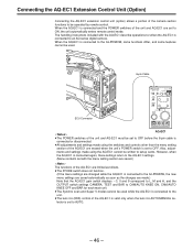
... level) to OFF before the remote control cable is connected or disconnected. ¥ 26-pin/12-pin output adaptor (option) (See page 98 for mounting method.) The 26-pin/12-pin output adaptor AJ-YA900P (option) is playing back, the camera's images are output at all times. - 17 - During recording, EE images can be performed simultaneously with the unit's built-in black and white). ∂ CAM OUT (camera output...
... level) to OFF before the remote control cable is connected or disconnected. ¥ 26-pin/12-pin output adaptor (option) (See page 98 for mounting method.) The 26-pin/12-pin output adaptor AJ-YA900P (option) is playing back, the camera's images are output at all times. - 17 - During recording, EE images can be performed simultaneously with the unit's built-in black and white). ∂ CAM OUT (camera output...

AJPD900W User Guide
Page 22
.... The brightness when lighted can be advanced continuously regardless of unedited shots. " TALLY switch This controls the tally lamp -. LOW: The tally lamp is to the VTR section, remaining battery level, sound level, time data, etc. OFF: The back tally lamp does not operate. ' WARNING lamp This flashes or lights when trouble occurs in the VTR section. ÷ LIGHT switch ON: This illuminates the display window ◊.
.... The brightness when lighted can be advanced continuously regardless of unedited shots. " TALLY switch This controls the tally lamp -. LOW: The tally lamp is to the VTR section, remaining battery level, sound level, time data, etc. OFF: The back tally lamp does not operate. ' WARNING lamp This flashes or lights when trouble occurs in the VTR section. ÷ LIGHT switch ON: This illuminates the display window ◊.

AJPD900W User Guide
Page 30
... clamping screw. 4 Set the zoom ring to the telephoto position manually or by electric drive. 5 Shoot the flange back adjustment chart and turn the distance ring to bring the chart into focus. 6 Set the zoom ring to the wide-angle position. 7 Turn the Ff ring to the image formation surface). Approx. 3 m Adjusting the Flange Back 1 Set the lens iris to adjust the flange back with the lens Handling Instructions.
... clamping screw. 4 Set the zoom ring to the telephoto position manually or by electric drive. 5 Shoot the flange back adjustment chart and turn the distance ring to bring the chart into focus. 6 Set the zoom ring to the wide-angle position. 7 Turn the Ff ring to the image formation surface). Approx. 3 m Adjusting the Flange Back 1 Set the lens iris to adjust the flange back with the lens Handling Instructions.
AJPD900W User Guide
Page 46
... lens iris AUTO/MANUAL selector is connected to CAM/AUTO KNEE ON, CAM/AUTO KNEE OFF and BAR for when the AQ-EC1 is set to AUTO. - 46 - Also, adjustments and settings made .) Note that the AQ-EC1 gain switch displays p3, 0 and 9 correspond to L, M and H, and the OUTPUT switch settings CAMERA, TEST and BAR to an AQ series digital camera. When the AQ-EC1 is set to OFF. The handling instructions...
... lens iris AUTO/MANUAL selector is connected to CAM/AUTO KNEE ON, CAM/AUTO KNEE OFF and BAR for when the AQ-EC1 is set to AUTO. - 46 - Also, adjustments and settings made .) Note that the AQ-EC1 gain switch displays p3, 0 and 9 correspond to L, M and H, and the OUTPUT switch settings CAMERA, TEST and BAR to an AQ series digital camera. When the AQ-EC1 is set to OFF. The handling instructions...
AJPD900W User Guide
Page 47
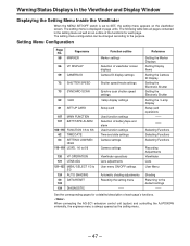
... When the MENU SET/OFF switch is displayed in the setting menu as well as the setting menu. - 47 - Lamp Display Setup card operations -- -- Reference Setting the Marker Displays Setting Display Items Setting the Camera ID Display Setting the Electronic Shutter Setting the Electronic Shutter Setting the ! The setting menu is set to 3/3 124 AUTO SHADING 50 DATA RESET 124 124 DIAGNOSTIC Function outline Marker settings Selection of battery/tape end alarm Used function settings Time and date settings Camera settings Camera settings Viewfinder operations Lens adjustments User menu ON...
... When the MENU SET/OFF switch is displayed in the setting menu as well as the setting menu. - 47 - Lamp Display Setup card operations -- -- Reference Setting the Marker Displays Setting Display Items Setting the Camera ID Display Setting the Electronic Shutter Setting the Electronic Shutter Setting the ! The setting menu is set to 3/3 124 AUTO SHADING 50 DATA RESET 124 124 DIAGNOSTIC Function outline Marker settings Selection of battery/tape end alarm Used function settings Time and date settings Camera settings Camera settings Viewfinder operations Lens adjustments User menu ON...

AJPD900W User Guide
Page 59
... UP (or DOWN) button until the CAMERA ID page shown below appears. (This operation can also be performed using the PAGEoUP/DOWN function.) - Pressing the DOWN button changes the character display in which the previous setting menu operations were completed appears on the viewfinder screen. (When the menu is used for the COLOR BAR selection on the VF DISPLAY page is being recorded. The area under the...
... UP (or DOWN) button until the CAMERA ID page shown below appears. (This operation can also be performed using the PAGEoUP/DOWN function.) - Pressing the DOWN button changes the character display in which the previous setting menu operations were completed appears on the viewfinder screen. (When the menu is used for the COLOR BAR selection on the VF DISPLAY page is being recorded. The area under the...

AJPD900W User Guide
Page 61
... frame mode SLAVE: This lamp lights when the time code is recorded or played back with an aspect ratio of 16:9. WIDE: This lamp lights when a tape is locked to indicate the time code, CTL and real time displays. Relationship between displayed items and switch settings. Time code-related switch settings and display items TCG switch position SET F-RUN or R-RUN DISPLAY switch position TC or CTL UB CTL TC UB Displayed item Time code User bit CTL Time code User...
... frame mode SLAVE: This lamp lights when the time code is recorded or played back with an aspect ratio of 16:9. WIDE: This lamp lights when a tape is locked to indicate the time code, CTL and real time displays. Relationship between displayed items and switch settings. Time code-related switch settings and display items TCG switch position SET F-RUN or R-RUN DISPLAY switch position TC or CTL UB CTL TC UB Displayed item Time code User bit CTL Time code User...

AJPD900W User Guide
Page 63
Adjustments and Setup During Recording Adjustments and Setup Using the Setting Menu Adjustments and setup operations during recording are performed at the setting menu are basically performed according to the item. Items which can be used Setting the synchro scan mode shutter speed Selecting required functions Shading adjustment Setup card data operations SHUTTER SPEED SYNCHRO SCAN FUNCTION 1/5 to 5/5 AUTO SHADING SET UP CARD Operation reference Setting the Gain Selector Value, Setting the DTL and gamma, etc. However, these procedures vary slightly according to the procedures...
Adjustments and Setup During Recording Adjustments and Setup Using the Setting Menu Adjustments and setup operations during recording are performed at the setting menu are basically performed according to the item. Items which can be used Setting the synchro scan mode shutter speed Selecting required functions Shading adjustment Setup card data operations SHUTTER SPEED SYNCHRO SCAN FUNCTION 1/5 to 5/5 AUTO SHADING SET UP CARD Operation reference Setting the Gain Selector Value, Setting the DTL and gamma, etc. However, these procedures vary slightly according to the procedures...
AJPD900W User Guide
Page 68
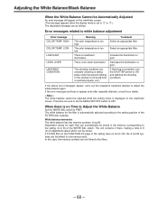
... attempts, consult your dealer. |Note{ The white balance cannot be adjusted while the setting menu is displayed on the viewfinder screen. (The message appears when the display mode is set the MENU SET/OFF switch to the setting position of the setting menu is automatically adjusted according to OFF. Adjusting the White Balance/Black Balance When the White Balance Cannot be Automatically Adjusted An error message will appear on the viewfinder screen. The color temperature is too high. Decrease the...
... attempts, consult your dealer. |Note{ The white balance cannot be adjusted while the setting menu is displayed on the viewfinder screen. (The message appears when the display mode is set the MENU SET/OFF switch to the setting position of the setting menu is automatically adjusted according to OFF. Adjusting the White Balance/Black Balance When the White Balance Cannot be Automatically Adjusted An error message will appear on the viewfinder screen. The color temperature is too high. Decrease the...
AJPD900W User Guide
Page 77
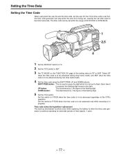
...'s operation. SHIFT/ITEM button: This is used to cause the digit which is being set, causing the set within the range of 00:00:00:00 to 23:59:59:29. 1 2,5 4 1 Set the DISPLAY switch to TC. 2 Set the TCG switch to SET. 3 Set TC MODE on the FUNCTION 3/5 page of the flashing digit. DOWN button: This decrements by 1 the figure of the setting menu to become inaccurate. Time code status during battery replacement...
...'s operation. SHIFT/ITEM button: This is used to cause the digit which is being set, causing the set within the range of 00:00:00:00 to 23:59:59:29. 1 2,5 4 1 Set the DISPLAY switch to TC. 2 Set the TCG switch to SET. 3 Set TC MODE on the FUNCTION 3/5 page of the flashing digit. DOWN button: This decrements by 1 the figure of the setting menu to become inaccurate. Time code status during battery replacement...

AJPD900W User Guide
Page 80
... battery to an external power supply during external locking While the time code is locked to an external source, the camera section is locked instantly to the user bit of the time code cannot be set the VTR to the GENLOCK IN connector. - 80 - Setting the Time Data External Lock Operation Procedure 3 2 1 1 Set the POWER switch to ON. 2 Set the F-RUN/R-RUN switch to F-RUN. 3 Set the DISPLAY switch to TC. 4 Supply reference time code and reference video...
... battery to an external power supply during external locking While the time code is locked to an external source, the camera section is locked instantly to the user bit of the time code cannot be set the VTR to the GENLOCK IN connector. - 80 - Setting the Time Data External Lock Operation Procedure 3 2 1 1 Set the POWER switch to ON. 2 Set the F-RUN/R-RUN switch to F-RUN. 3 Set the DISPLAY switch to TC. 4 Supply reference time code and reference video...
AJPD900W User Guide
Page 85
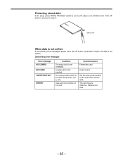
... card is set to ON, data is not rewritten even if the UP button is pressed in step 5, the data is not written. The write protect switch on the side of the card to OFF. Replace the card. - 85 - Insert a card. Set the write protect switch on the card. Protecting stored data If the setup card's WRITE PROTECT switch is set to ON. Data cannot be defective. A setup card is not formatted...
... card is set to ON, data is not rewritten even if the UP button is pressed in step 5, the data is not written. The write protect switch on the side of the card to OFF. Replace the card. - 85 - Insert a card. Set the write protect switch on the card. Protecting stored data If the setup card's WRITE PROTECT switch is set to ON. Data cannot be defective. A setup card is not formatted...

AJPD900W User Guide
Page 100
... on viewfinder screen Images shot by camera. Search operation for setting menu MAIN FUNCTION and the VTR status. » Lens RET button functions RET switch setting REC CHECK CAM RETF Internal VTR mode Recording Recording paused Playing Playback paused Recording Recording paused Playing Playback paused Description of what appears on the viewfinder screen when the RET (return) button is pressed or while it is connected with the peripheral devices. - 100 - Internal VTR's playback images. Return video signal which has been input from an external source. Return video signal which...
... on viewfinder screen Images shot by camera. Search operation for setting menu MAIN FUNCTION and the VTR status. » Lens RET button functions RET switch setting REC CHECK CAM RETF Internal VTR mode Recording Recording paused Playing Playback paused Recording Recording paused Playing Playback paused Description of what appears on the viewfinder screen when the RET (return) button is pressed or while it is connected with the peripheral devices. - 100 - Internal VTR's playback images. Return video signal which has been input from an external source. Return video signal which...

AJPD900W User Guide
Page 109
...'s Intelligent Battery is switched off , and regeneration is not displayed. If the camera is displayed. Time code DF/NDF switching DF: Drop frame mode NDF: Non-drop frame mode LTC UB usage method selection USER: User setting (fixed value) REAL: Real-time operation according to DIGITAL. TCG operation selection when TCG SET>power OFF>power ON>REC is used for the recording/pause hold time. 10: 10 minutes 20: 20 minutes 30: 30 minutes Battery type selectionF NiCd...
...'s Intelligent Battery is switched off , and regeneration is not displayed. If the camera is displayed. Time code DF/NDF switching DF: Drop frame mode NDF: Non-drop frame mode LTC UB usage method selection USER: User setting (fixed value) REAL: Real-time operation according to DIGITAL. TCG operation selection when TCG SET>power OFF>power ON>REC is used for the recording/pause hold time. 10: 10 minutes 20: 20 minutes 30: 30 minutes Battery type selectionF NiCd...
AJPD900W User Guide
Page 116
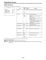
... MANUAL KNEE KNEE POINT KNEE SLOPE WHITE CLIP WHITE CLIP LVL Variable range p...100 o...0 o100 0% 7.5% 7.5%A ON OFF 1...97 219 0... 18... 25 ON OFF 90... % 110% VF display ENG ENG ENG ENG ENG Remarks M.PED (Master pedestal level) setting Setup level switching 0%: 0% setup for both camera output and tape. 7.5%: 7.5% setup for both camera output and tape. 7.5%A: 7.5% setup for camera output; 0% setup for tape. FWhen the setting is set to adjust again. Menu screen display methods USER menu: Setting the MENU switch to SET displays the ENG menu...
... MANUAL KNEE KNEE POINT KNEE SLOPE WHITE CLIP WHITE CLIP LVL Variable range p...100 o...0 o100 0% 7.5% 7.5%A ON OFF 1...97 219 0... 18... 25 ON OFF 90... % 110% VF display ENG ENG ENG ENG ENG Remarks M.PED (Master pedestal level) setting Setup level switching 0%: 0% setup for both camera output and tape. 7.5%: 7.5% setup for both camera output and tape. 7.5%A: 7.5% setup for camera output; 0% setup for tape. FWhen the setting is set to adjust again. Menu screen display methods USER menu: Setting the MENU switch to SET displays the ENG menu...

AJPD900W User Guide
Page 130
... PEAKING controls so that the color bar appears clearly on the viewfinder. 3 Check the following operations to check that the (!) lamp lights when the items set to ON at the (!) LED page are operated. (1) Set the gain to any value other than 0 dB with the cursor changes. 4 Set the OUTPUT/AUTO KNEE switch to CAM and switch the FILTER knob to CH1. Set the unit to engineer mode, set DISPLAY MODE...
... PEAKING controls so that the color bar appears clearly on the viewfinder. 3 Check the following operations to check that the (!) lamp lights when the items set to ON at the (!) LED page are operated. (1) Set the gain to any value other than 0 dB with the cursor changes. 4 Set the OUTPUT/AUTO KNEE switch to CAM and switch the FILTER knob to CH1. Set the unit to engineer mode, set DISPLAY MODE...
AJPD900W User Guide
Page 132
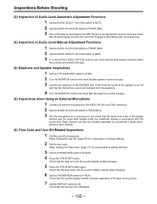
... button again. Inspections Before Shooting (2) Inspection of Audio Level Automatic Adjustment Functions 1 Set the AUDIO SELECT CH1/CH2 switch to AUTO. 2 Set the AUDIO IN CH1/CH2 switch to FRONT [MIC]. 3 Aim a microphone connected to the MIC IN jack at a sound source and check that the set user bit is cut off and that the microphone sound can also be heard from the earphone. 4 Turn the MONITOR control and check that the earphone volume changes. (5) Inspections when Using an External Microphone 1 Connect...
... button again. Inspections Before Shooting (2) Inspection of Audio Level Automatic Adjustment Functions 1 Set the AUDIO SELECT CH1/CH2 switch to AUTO. 2 Set the AUDIO IN CH1/CH2 switch to FRONT [MIC]. 3 Aim a microphone connected to the MIC IN jack at a sound source and check that the set user bit is cut off and that the microphone sound can also be heard from the earphone. 4 Turn the MONITOR control and check that the earphone volume changes. (5) Inspections when Using an External Microphone 1 Connect...


