
AJD455 User Guide
Page 1
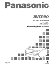
P Operating Instructions Printed in Japan VQT9172 P S0401H D Digital Video Cassette Recorder AJ-
P Operating Instructions Printed in Japan VQT9172 P S0401H D Digital Video Cassette Recorder AJ-
AJD455 User Guide
Page 2
..., do not make any unauthorized modifications. Ensure that the installation is the safety information. 2 FCC Note: This device complies with the instruction manual, may be ...REMOVE COVER (OR BACK). NO USER-SERVICEABLE PARTS INSIDE. IMPORTANT "Unauthorized recording of copyrighted television programs, video tapes and other materials do not obstruct the ventilation condition to prevent risk of electric shock or fire hazard due to overheating. The exclamation point within an equilateral triangle, is operated in order to keep well ventilated condition. This equipment generates, uses...
..., do not make any unauthorized modifications. Ensure that the installation is the safety information. 2 FCC Note: This device complies with the instruction manual, may be ...REMOVE COVER (OR BACK). NO USER-SERVICEABLE PARTS INSIDE. IMPORTANT "Unauthorized recording of copyrighted television programs, video tapes and other materials do not obstruct the ventilation condition to prevent risk of electric shock or fire hazard due to overheating. The exclamation point within an equilateral triangle, is operated in order to keep well ventilated condition. This equipment generates, uses...
AJD455 User Guide
Page 3
... Digital video interface board • AJ-YA752P Audio memory unit 3 Contents General and Features 4 Controls and their functions Controls and their functions 6 • Front panel 6 • Connector area 11 Tapes 14 Setup menus Setup (default settings 15 Setup menus 16 • SYSTEM menu 20 • USER menu 22 • BASIC menu 22 • OPERATION menu 24 • INTERFACE menu 26 • EDIT menu 27 • TAPE PROTECT menu 30 • TIME CODE menu 31 • VIDEO menu...
... Digital video interface board • AJ-YA752P Audio memory unit 3 Contents General and Features 4 Controls and their functions Controls and their functions 6 • Front panel 6 • Connector area 11 Tapes 14 Setup menus Setup (default settings 15 Setup menus 16 • SYSTEM menu 20 • USER menu 22 • BASIC menu 22 • OPERATION menu 24 • INTERFACE menu 26 • EDIT menu 27 • TAPE PROTECT menu 30 • TIME CODE menu 31 • VIDEO menu...
AJD455 User Guide
Page 4
... at a speed of the tapes measures 1/4 inch to the internal time code, an external time code input or input signal VITC can be recorded in the machine. 4 Features Compact size and light weight This is used for the unit's setup can be performed while viewing the screen menus on consumer-use cassette tapes shot by exercising control from dubbing is a digital video cassette recorder which uses 1/4-inch tapes. Dialy shuttle operation is used , the image shakes slightly in the vertical direction. In addition...
... at a speed of the tapes measures 1/4 inch to the internal time code, an external time code input or input signal VITC can be recorded in the machine. 4 Features Compact size and light weight This is used for the unit's setup can be performed while viewing the screen menus on consumer-use cassette tapes shot by exercising control from dubbing is a digital video cassette recorder which uses 1/4-inch tapes. Dialy shuttle operation is used , the image shakes slightly in the vertical direction. In addition...
AJD455 User Guide
Page 5
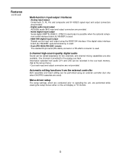
... cue track memory. (Set at the set up menu.) • Cue track input and output connectors are performed while viewing the setup menus either on the unit display or TV monitor. 5 Features (continued) Multi-function input/output interfaces • Analog input/output Component (Y, PB, PR) and composite and S1-VIDEO signal input and output connectors are provided. • Digital audio input/output AES/EBU audio BNC input and output connectors are provided. • Serial digital input/output Serial digital (SMPTE 259M-C, 272M-C) input/output...
... cue track memory. (Set at the set up menu.) • Cue track input and output connectors are performed while viewing the setup menus either on the unit display or TV monitor. 5 Features (continued) Multi-function input/output interfaces • Analog input/output Component (Y, PB, PR) and composite and S1-VIDEO signal input and output connectors are provided. • Digital audio input/output AES/EBU audio BNC input and output connectors are provided. • Serial digital input/output Serial digital (SMPTE 259M-C, 272M-C) input/output...
AJD455 User Guide
Page 7
... time code. Blue: This lights when the error rate for the cassette. Red: This lights when the video or audio signals are both acceptable. q POWER switch When the ON side is pressed, the power is possible. w Cassette insertion slot e EJECT button When this lamp lights. u Tape counter type display CTL: This indicates the tape timer (control signal). i SCH lamp This lights when the SCH phase of these lamps lights in 16:9 wide screen mode...
... time code. Blue: This lights when the error rate for the cassette. Red: This lights when the video or audio signals are both acceptable. q POWER switch When the ON side is pressed, the power is possible. w Cassette insertion slot e EJECT button When this lamp lights. u Tape counter type display CTL: This indicates the tape timer (control signal). i SCH lamp This lights when the SCH phase of these lamps lights in 16:9 wide screen mode...
AJD455 User Guide
Page 8
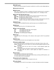
... the PLAY button. !9 PLAY button Playback commences when this button is pressed. When it is set to TAPE, still pictures can be monitored on stereo headphones when they are calculated. !5 RESET button When this is pressed during playback, search, fast forward or rewind, EE mode images and audio signals can be monitored. DV recording is performed when a consumer-use DV cassette has been inserted. @1 REC button Recording commences when this button is displayed. " at EJECT...
... the PLAY button. !9 PLAY button Playback commences when this button is pressed. When it is set to TAPE, still pictures can be monitored on stereo headphones when they are calculated. !5 RESET button When this is pressed during playback, search, fast forward or rewind, EE mode images and audio signals can be monitored. DV recording is performed when a consumer-use DV cassette has been inserted. @1 REC button Recording commences when this button is displayed. " at EJECT...
AJD455 User Guide
Page 9
... operation during the setup menu mode. (For details, see setup menu items (page 15). #1 SET button The time code is set or the data selected for the setup menu settings are entered by pressing this button. (For details, refer to the right. , : These change the flashing digit in the time code indicators. @3 Volume control This is used to adjust the headphones volume. @4 Audio recording level controls* These are used , the superimposed display appears at menu setup. , : These change the flashing digit in the time code...
... operation during the setup menu mode. (For details, see setup menu items (page 15). #1 SET button The time code is set or the data selected for the setup menu settings are entered by pressing this button. (For details, refer to the right. , : These change the flashing digit in the time code indicators. @3 Volume control This is used to adjust the headphones volume. @4 Audio recording level controls* These are used , the superimposed display appears at menu setup. , : These change the flashing digit in the time code...
AJD455 User Guide
Page 10
... digital video interface board (optional accessory) is required for this position when recording digital video interface signals (IEEE1394). (At the same time, audio input signals from an external component using the REMOTE, RS-232C or digital video interface (IEEE1394) connector. LOCAL: Set here to correspond with the REF VIDEO signal must be supplied. #5 REMOTE/LOCAL switch This is set to control the unit by pressing the cursor buttons ( , ). CMPST: For recording...
... digital video interface board (optional accessory) is required for this position when recording digital video interface signals (IEEE1394). (At the same time, audio input signals from an external component using the REMOTE, RS-232C or digital video interface (IEEE1394) connector. LOCAL: Set here to correspond with the REF VIDEO signal must be supplied. #5 REMOTE/LOCAL switch This is set to control the unit by pressing the cursor buttons ( , ). CMPST: For recording...
AJD455 User Guide
Page 12
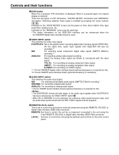
... connected here to adjust the video output signal settings externally. 12 r TIME CODE IN/OUT connectors These are connected by a loop-through configuration. For termination, set the switch to reduce the noise. o REMOTE connector (RS-422A connector) The unit's operations can be controlled by connecting an external controller to the unit using this connector. !0 ANALOG AUDIO CH1/CH2 connectors These are the analog audio CH1 and CH2 input connectors. !1 S1-VIDEO...
... connected here to adjust the video output signal settings externally. 12 r TIME CODE IN/OUT connectors These are connected by a loop-through configuration. For termination, set the switch to reduce the noise. o REMOTE connector (RS-422A connector) The unit's operations can be controlled by connecting an external controller to the unit using this connector. !0 ANALOG AUDIO CH1/CH2 connectors These are the analog audio CH1 and CH2 input connectors. !1 S1-VIDEO...
AJD455 User Guide
Page 14
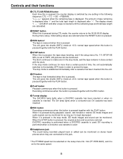
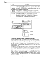
... TIMER time is set to refrain from the controller or personal computer (when the AJYAD455P digital video interface board is used) which have been recorded in mind that recordings cannot be disturbed during slow motion playback of consumer-use tapes. • From the viewpoint of protecting the tape, minimize repeated cue-up at a rate of Panasonic consumer DV cassette tapes is automatically loaded. ON POWER OFF LEVEL HEADPHONES CH 1 AUDIO...
... TIMER time is set to refrain from the controller or personal computer (when the AJYAD455P digital video interface board is used) which have been recorded in mind that recordings cannot be disturbed during slow motion playback of consumer-use tapes. • From the viewpoint of protecting the tape, minimize repeated cue-up at a rate of Panasonic consumer DV cassette tapes is automatically loaded. ON POWER OFF LEVEL HEADPHONES CH 1 AUDIO...

AJD455 User Guide
Page 15
... S-VIDEO VIDEO IN SET SDI AES/EBU ANALOG AUDIO IN DIAG PAGE REMOTE LOCAL 2, 3 15 is incremented for the user file currently being used . The changes are hooked up. appears on ; now flashes. when the button is pressed, it is decremented. 4 Repeat steps 2 and 3 to change is to be made , press the MENU button without pressing the SET button. on menus. When the button is displayed. Setup (default settings) The unit...
... S-VIDEO VIDEO IN SET SDI AES/EBU ANALOG AUDIO IN DIAG PAGE REMOTE LOCAL 2, 3 15 is incremented for the user file currently being used . The changes are hooked up. appears on ; now flashes. when the button is pressed, it is decremented. 4 Repeat steps 2 and 3 to change is to be made , press the MENU button without pressing the SET button. on menus. When the button is displayed. Setup (default settings) The unit...

AJD455 User Guide
Page 17
...;) on the menu screen. A03 (MENU LOCK) for the system or user file. 4 Press the or button, and select lock mode setting or release. To release the lock: Select the 0000 (OFF) setting. SETUP-MENU LOCKED NO.000 - 0005 ∗000 P-ROLL TIME 5s 001 CHARA H-POS 5 002 CHARA V-POS 23 003 DISPLAY SEL T&STA 004 LOCAL ENA ST&EJ 005 TAPE TIMER ±12h 006 SUPER ON 007...
...;) on the menu screen. A03 (MENU LOCK) for the system or user file. 4 Press the or button, and select lock mode setting or release. To release the lock: Select the 0000 (OFF) setting. SETUP-MENU LOCKED NO.000 - 0005 ∗000 P-ROLL TIME 5s 001 CHARA H-POS 5 002 CHARA V-POS 23 003 DISPLAY SEL T&STA 004 LOCAL ENA ST&EJ 005 TAPE TIMER ±12h 006 SUPER ON 007...
AJD455 User Guide
Page 22
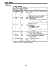
... 0... The mode display is exited, operation complies with the SUPER OFF/ON setting. Setup menus USER menu Item Superimposed No. However, when the menu is DVCPRO during DVCPRO playback, DV during DV playback, and DVCAM during DV or DVCAM playback only. The operation mode is displayed during DVCPRO playback. * The SERIAL OUT 3 connector functions only when the AJ-YA455P serial interface board (optional accessory) is changed so that...
... 0... The mode display is exited, operation complies with the SUPER OFF/ON setting. Setup menus USER menu Item Superimposed No. However, when the menu is DVCPRO during DVCPRO playback, DV during DV playback, and DVCAM during DV or DVCAM playback only. The operation mode is displayed during DVCPRO playback. * The SERIAL OUT 3 connector functions only when the AJ-YA455P serial interface board (optional accessory) is changed so that...

AJD455 User Guide
Page 25
... automatically. 1. picture mode depending on the cassette tape is set to enable or disable the operation of what has been selected as the setup menu item No. 114 (REC INHIBIT) setting, the REC INHIBIT lamp will light all the time regardless of the front panel's EJECT button. 0: The button's operation is disabled in the recording mode. 1: The button's operation is to flash or light when the cassette has been set to stop...
... automatically. 1. picture mode depending on the cassette tape is set to enable or disable the operation of what has been selected as the setup menu item No. 114 (REC INHIBIT) setting, the REC INHIBIT lamp will light all the time regardless of the front panel's EJECT button. 0: The button's operation is disabled in the recording mode. 1: The button's operation is to flash or light when the cassette has been set to stop...
AJD455 User Guide
Page 36
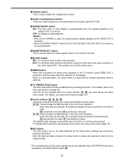
... to be used for the AUDIO MONITOR SELECT switch. The PCM AUDIO output CH1 and CH2 signals are output separately regardless of the position selected for the audio input signal. 0: The internal signal is not selected. 1: The internal signal is selected. • The internal signal has a frequency of 997 Hz. • This setting is superimposed. Setup menus USER menu (continued) Item Setting Superimposed...
... to be used for the AUDIO MONITOR SELECT switch. The PCM AUDIO output CH1 and CH2 signals are output separately regardless of the position selected for the audio input signal. 0: The internal signal is not selected. 1: The internal signal is selected. • The internal signal has a frequency of 997 Hz. • This setting is superimposed. Setup menus USER menu (continued) Item Setting Superimposed...
AJD455 User Guide
Page 39
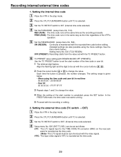
... button to change the value. 4 When the setting of the start number of the VTR's operation. 5 Set the REGEN MODE. (setup menu No. 504) ON (REGEN): Continuity is completed, press the SET button. FREE (RUN): The time code runs in real time 00:00:00:00 - 23:59:59:29 • User bit 00 00 00 00 - See the menu items below . • When using the menu settings. VITC: The input video...
... button to change the value. 4 When the setting of the start number of the VTR's operation. 5 Set the REGEN MODE. (setup menu No. 504) ON (REGEN): Continuity is completed, press the SET button. FREE (RUN): The time code runs in real time 00:00:00:00 - 23:59:59:29 • User bit 00 00 00 00 - See the menu items below . • When using the menu settings. VITC: The input video...
AJD455 User Guide
Page 44
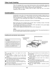
... a cold location to disassemble the recorder. s Cassette tape can be made. Installing the mechanism dust protector CAUTION: These servicing instructions are no user serviceable parts inside the mechanism. s Avoid operating or leaving the unit near strong magnetic fields. However, in damage both to the recorder and to be used for about 10 minutes rather than that the video heads be used only for possible damage. For...
... a cold location to disassemble the recorder. s Cassette tape can be made. Installing the mechanism dust protector CAUTION: These servicing instructions are no user serviceable parts inside the mechanism. s Avoid operating or leaving the unit near strong magnetic fields. However, in damage both to the recorder and to be used for about 10 minutes rather than that the video heads be used only for possible damage. For...

AJD455 User Guide
Page 50
HIGH/600Ω This sets the CH2 audio input impedance. Printed circuit board CAUTION: These servicing instructions are qualified to do so. HIGH/600Ω Factory setting HIGH HIGH 50 To reduce the risk of electric shock do not perform any servicing other than that contained in the operating instructions unless you are for use by qualified service personnel only. Printed circuit board F1 board AUDIO Abbr. name SW100 Full name Audio Input Impedance SW SW101 Audio Input Impedance SW Function This sets the CH1 audio input impedance.
HIGH/600Ω This sets the CH2 audio input impedance. Printed circuit board CAUTION: These servicing instructions are qualified to do so. HIGH/600Ω Factory setting HIGH HIGH 50 To reduce the risk of electric shock do not perform any servicing other than that contained in the operating instructions unless you are for use by qualified service personnel only. Printed circuit board F1 board AUDIO Abbr. name SW100 Full name Audio Input Impedance SW SW101 Audio Input Impedance SW Function This sets the CH1 audio input impedance.
AJD455 User Guide
Page 51
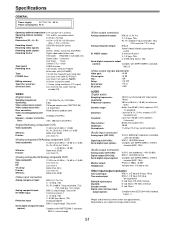
... change without notice. 51 Specifications are approximately. Recorded in sub-code area Digital audio; 2 channels Cue Track; 1 track Control (CTL); 1 track Tape speed: 33.820 mm/sec Recording time: 126 minutes (with AJ-P126LP) 66 minutes (with AJ-P66MP) Tape: 1/4-inch thin magnetic layer metal tape FF/REW time: Less than 3 min (with AJ-P126LP) Less than 2 min (with AJ-P66MP) Editing accuracy: Tape timer accuracy: Servo lock time: ±0 frame (using time code) ±1 frame (using...
... change without notice. 51 Specifications are approximately. Recorded in sub-code area Digital audio; 2 channels Cue Track; 1 track Control (CTL); 1 track Tape speed: 33.820 mm/sec Recording time: 126 minutes (with AJ-P126LP) 66 minutes (with AJ-P66MP) Tape: 1/4-inch thin magnetic layer metal tape FF/REW time: Less than 3 min (with AJ-P126LP) Less than 2 min (with AJ-P66MP) Editing accuracy: Tape timer accuracy: Servo lock time: ±0 frame (using time code) ±1 frame (using...


