
Memory Card Camcorder
Page 5
... any way, such as power-supply cord or plug is used, use caution when moving the cart/ apparatus combination to avoid injury from the apparatus. 11) Only use attachments/accessories specified by the manufacturer. 12) Use only with the cart, stand, tripod, bracket, or table specified by the manufacturer, or sold...
... any way, such as power-supply cord or plug is used, use caution when moving the cart/ apparatus combination to avoid injury from the apparatus. 11) Only use attachments/accessories specified by the manufacturer. 12) Use only with the cart, stand, tripod, bracket, or table specified by the manufacturer, or sold...
Memory Card Camcorder
Page 6
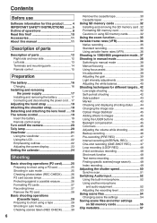
Contents Before use Software information for this product .......... 4 IMPORTANT SAFETY INSTRUCTIONS ......... 5 Outline of operations 8 Read this first 10 Accessories 11 About this manual 11 Description of parts Description of parts 12 Right side and rear side 12 Left side 13 Terminals and mounting parts 14 Remote control 15 Preparation ...
Contents Before use Software information for this product .......... 4 IMPORTANT SAFETY INSTRUCTIONS ......... 5 Outline of operations 8 Read this first 10 Accessories 11 About this manual 11 Description of parts Description of parts 12 Right side and rear side 12 Left side 13 Terminals and mounting parts 14 Remote control 15 Preparation ...

Memory Card Camcorder
Page 11
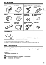
P2 : Explanations for tape usage only. 11 References • References are identified by the icons below. TAPE : Explanations for P2 card usage only. Icons Explanations specific to the camera-recorder. ∗1 For ...
P2 : Explanations for tape usage only. 11 References • References are identified by the icons below. TAPE : Explanations for P2 card usage only. Icons Explanations specific to the camera-recorder. ∗1 For ...

Memory Card Camcorder
Page 12
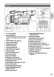
Description of parts Right side and rear side 3 5 79 11 19 4 68 10 12 18 20 1 2 2 1 13 PUSH 14 16 15 17 22 24 26 28 31 21 23 25 27 29 30 1 POWER switch (... button (Page 33) 8 Handle START/STOP button (Pages 25 and 29) 9 Pin hole (for zoom ring) (Page 13) 10 Built-in stereo microphone (Page 52) 11 Tally lamp (Front) (Page 20) 12 Remote control sensor (Front) 13 Cassette holder (Pages 29 and 30) 14 Cassette cover (Pages 29 and 30) 15...
Description of parts Right side and rear side 3 5 79 11 19 4 68 10 12 18 20 1 2 2 1 13 PUSH 14 16 15 17 22 24 26 28 31 21 23 25 27 29 30 1 POWER switch (... button (Page 33) 8 Handle START/STOP button (Pages 25 and 29) 9 Pin hole (for zoom ring) (Page 13) 10 Built-in stereo microphone (Page 52) 11 Tally lamp (Front) (Page 20) 12 Remote control sensor (Front) 13 Cassette holder (Pages 29 and 30) 14 Cassette cover (Pages 29 and 30) 15...

Memory Card Camcorder
Page 13
... 45) 32 INPUT1, 2 switch (MIC POWER +48 V) (Page 52) 13 Description of parts Left side 1 23 4 18 AWB ZOOM SERVO MANUAL 8 10 12 14 16 5 6 7 9 11 13 15 17 22 AUDIO DUB/ THUMBNAIL REC END SEARCH 23 19 SET 20 24 21 MENU PAGE/ AUDIO MON/VAR 25 26 27 BARS... (Page 33) 6 AWB button (Page 40) 7 FOCUS switch (Page 38) 8 PUSH AUTO button (Page 38) 9 IRIS dial (Page 39) 10 ND FILTER switch (Page 39) 11 IRIS button (Page 39) 12 GAIN switch (Page 39) 13 WHITE BAL switch (Page 40) 14 DISP/MODE CHK button (Page 44) 15 USER button...
... 45) 32 INPUT1, 2 switch (MIC POWER +48 V) (Page 52) 13 Description of parts Left side 1 23 4 18 AWB ZOOM SERVO MANUAL 8 10 12 14 16 5 6 7 9 11 13 15 17 22 AUDIO DUB/ THUMBNAIL REC END SEARCH 23 19 SET 20 24 21 MENU PAGE/ AUDIO MON/VAR 25 26 27 BARS... (Page 33) 6 AWB button (Page 40) 7 FOCUS switch (Page 38) 8 PUSH AUTO button (Page 38) 9 IRIS dial (Page 39) 10 ND FILTER switch (Page 39) 11 IRIS button (Page 39) 12 GAIN switch (Page 39) 13 WHITE BAL switch (Page 40) 14 DISP/MODE CHK button (Page 44) 15 USER button...

Memory Card Camcorder
Page 14
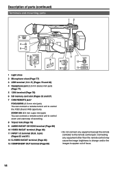
Description of parts (continued) Terminals and mounting parts 12 3 USB 2.0 4 1394 5 6 CAM REMOTE ZOOM SS FOCUS IRIS 7 11 S-VIDEO 8 9 CH1 IN/ AUDIO OUT IN/OUT 12 CH2 IN/ OUT 10 VIDEO COMPONENT OUT 13 1 Light shoe 2 Microphone shoe (Page 76) 3 USB terminal (Mini-B) (... zoom and start/stop of recording. 8 Tripod hole (Page 10) 9 AUDIO IN/OUT CH1/CH2 terminal (Page 79) 10 VIDEO IN/OUT terminal (Page 79) 11 INPUT 1/2 terminal (XLR, 3 pin) (Pages 52 and 80) 12 S-VIDEO IN/OUT terminal (Page 79) 13 COMPONENT OUT terminal (Page 79) ∗ Do not connect...
Description of parts (continued) Terminals and mounting parts 12 3 USB 2.0 4 1394 5 6 CAM REMOTE ZOOM SS FOCUS IRIS 7 11 S-VIDEO 8 9 CH1 IN/ AUDIO OUT IN/OUT 12 CH2 IN/ OUT 10 VIDEO COMPONENT OUT 13 1 Light shoe 2 Microphone shoe (Page 76) 3 USB terminal (Mini-B) (... zoom and start/stop of recording. 8 Tripod hole (Page 10) 9 AUDIO IN/OUT CH1/CH2 terminal (Page 79) 10 VIDEO IN/OUT terminal (Page 79) 11 INPUT 1/2 terminal (XLR, 3 pin) (Pages 52 and 80) 12 S-VIDEO IN/OUT terminal (Page 79) 13 COMPONENT OUT terminal (Page 79) ∗ Do not connect...

Memory Card Camcorder
Page 15
... 33 and 75) 16 VAR. buttons Function the same as the START/STOP button on the camera. ZOOM MENU SET ITEM 14 4 5 15 13 10 11 17 Used during VCR mode 7 PLAY button ( ) (Page 62) 8 /REW button ( ) (Page 62) 9 PAUSE button ( ) (Page 62) Like the operation buttons of parts... Remote control The following buttons are performed using SET button. 10 STILL ADV button ( , ) (Page 73) 11 INDEX buttons ( , ) (Page 75) 12 STOP button ( ) (Page 62) 13 FF/ button ( ) (Page 62) Buttons for functions that cannot be executed on the ...
... 33 and 75) 16 VAR. buttons Function the same as the START/STOP button on the camera. ZOOM MENU SET ITEM 14 4 5 15 13 10 11 17 Used during VCR mode 7 PLAY button ( ) (Page 62) 8 /REW button ( ) (Page 62) 9 PAUSE button ( ) (Page 62) Like the operation buttons of parts... Remote control The following buttons are performed using SET button. 10 STILL ADV button ( , ) (Page 73) 11 INDEX buttons ( , ) (Page 75) 12 STOP button ( ) (Page 62) 13 FF/ button ( ) (Page 62) Buttons for functions that cannot be executed on the ...

Memory Card Camcorder
Page 34
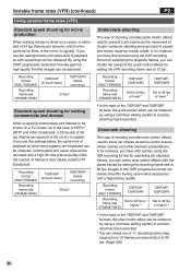
... the camera-recorder records only the effective frames (native recording), recording is possible only in the 24P, 30P or 60P mode (standard recording). As with Panasonic's Varicam model (AJ-HDC27 series), this unit also provides a recording format that allow recording by the camera-recorder (Page 129) There may be set for... at which the images are actually recorded 60 48 36 32 30 26 24 22 20 18 12 59.94 48.17 35.68 32.11 29.97 26.44 23.98 22.48 19.55 17.98 12.26 34 Refer to 60 fps. Recording frame rate displayed Frame rate...
... the camera-recorder records only the effective frames (native recording), recording is possible only in the 24P, 30P or 60P mode (standard recording). As with Panasonic's Varicam model (AJ-HDC27 series), this unit also provides a recording format that allow recording by the camera-recorder (Page 129) There may be set for... at which the images are actually recorded 60 48 36 32 30 26 24 22 20 18 12 59.94 48.17 35.68 32.11 29.97 26.44 23.98 22.48 19.55 17.98 12.26 34 Refer to 60 fps. Recording frame rate displayed Frame rate...
Memory Card Camcorder
Page 36
... is the norm (1x speed). If, for making movies to show car chases as well as with a high film-like images can select any of 11 recording frame rates ranging from 12 frames per second) is also ideally suited to process what has been recorded. If you have shot scenes using...
... is the norm (1x speed). If, for making movies to show car chases as well as with a high film-like images can select any of 11 recording frame rates ranging from 12 frames per second) is also ideally suited to process what has been recorded. If you have shot scenes using...

Memory Card Camcorder
Page 55
... SAVE has not been selected. • To return the scene file settings to the factory settings, select INITIAL in step 9, then do steps 10 to 11. 9 Press button, and use button to select YES. Shooting 55 Press button. 6 The screen below is displayed, so set , the characters are cleared. 10 The... filename, press the MENU button. • The name change will not be completed unless you have finished step 10. 8 Press button to select SAVE/INIT. 11 Press MENU twice to exit the menus. • The original scene file settings will be restored when the power is pressed when the filename has...
... SAVE has not been selected. • To return the scene file settings to the factory settings, select INITIAL in step 9, then do steps 10 to 11. 9 Press button, and use button to select YES. Shooting 55 Press button. 6 The screen below is displayed, so set , the characters are cleared. 10 The... filename, press the MENU button. • The name change will not be completed unless you have finished step 10. 8 Press button to select SAVE/INIT. 11 Press MENU twice to exit the menus. • The original scene file settings will be restored when the power is pressed when the filename has...
Memory Card Camcorder
Page 91
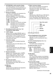
... screen, 1394 CONTROL, you have selected "ON". 10 AWB error LOWLIGHT: Appears when the brightness level adjusted by the auto white balance is too low. 11 Marker luminance display When markers are displayed while you hold down the DISP/ MODE CHK button. 8 Squeeze information Appears when in the setup menus, CAMERA...
... screen, 1394 CONTROL, you have selected "ON". 10 AWB error LOWLIGHT: Appears when the brightness level adjusted by the auto white balance is too low. 11 Marker luminance display When markers are displayed while you hold down the DISP/ MODE CHK button. 8 Squeeze information Appears when in the setup menus, CAMERA...

Memory Card Camcorder
Page 116
...:00 - 01:00 - 02:00 - 03:00 - 04:00 - 05:00 - 06:00 - 07:00 - 08:00 - 09:00 - 10:00 - 11:00 - 12:00 + 13:00 + 12:00 + 11:00 + 10:00 + 09:00 + 08:00 + 07:00 + 06:00 + 05:00 + 04:00 + 03:00 + 02:00 + 01:00 Area... Europe Time difference - 00:30 - 01:30 - 02:30 - 03:30 - 04:30 - 05:30 - 06:30 - 07:30 - 08:30 - 09:30 - 10:30 - 11:30 + 11:30 + 10:30 + 09:30 + 08:30 + 07:30 + 06:30 + 05:30 + 04:30 + 03:30 + 02:30 + 01:30 + 00:30 + 12...
...:00 - 01:00 - 02:00 - 03:00 - 04:00 - 05:00 - 06:00 - 07:00 - 08:00 - 09:00 - 10:00 - 11:00 - 12:00 + 13:00 + 12:00 + 11:00 + 10:00 + 09:00 + 08:00 + 07:00 + 06:00 + 05:00 + 04:00 + 03:00 + 02:00 + 01:00 Area... Europe Time difference - 00:30 - 01:30 - 02:30 - 03:30 - 04:30 - 05:30 - 06:30 - 07:30 - 08:30 - 09:30 - 10:30 - 11:30 + 11:30 + 10:30 + 09:30 + 08:30 + 07:30 + 06:30 + 05:30 + 04:30 + 03:30 + 02:30 + 01:30 + 00:30 + 12...

Memory Card Camcorder
Page 131
..., 1/120, 1/250, 1/500, 1/1000 sec. to 350° (When FILM CAM is used) 14.0 W (max.) indicates safety information. Specifications [GENERAL] Supply voltage: DC7.2 V/7.9 V Power consumption 11.6 W (when the viewfinder is used) 12.0 W (when the LCD monitor is set in 0.5° steps from 10° to 1/249.8 sec. 30P/30PN mode: 1/30...
..., 1/120, 1/250, 1/500, 1/1000 sec. to 350° (When FILM CAM is used) 14.0 W (max.) indicates safety information. Specifications [GENERAL] Supply voltage: DC7.2 V/7.9 V Power consumption 11.6 W (when the viewfinder is used) 12.0 W (when the LCD monitor is set in 0.5° steps from 10° to 1/249.8 sec. 30P/30PN mode: 1/30...
P2 Camcoder
Page 5
.... 10) Protect the power cord from being walked on or pinched particularly at plugs, convenience receptacles, and the point where they exit from the apparatus. 11) Only use caution when moving the cart/ apparatus combination to avoid injury from tip-over. 13) Unplug this apparatus near any ventilation openings. A polarized plug...
.... 10) Protect the power cord from being walked on or pinched particularly at plugs, convenience receptacles, and the point where they exit from the apparatus. 11) Only use caution when moving the cart/ apparatus combination to avoid injury from tip-over. 13) Unplug this apparatus near any ventilation openings. A polarized plug...
P2 Camcoder
Page 6
Contents Read this first 2 Before use Recommendation for Use of Genuine Panasonic Battery Pack (Rechargeable Battery 4 Software information for this product .......... 4 IMPORTANT SAFETY INSTRUCTIONS ......... 5 Outline of operations 8 Precaution for use 10 Accessories 11 About this manual 11 Description of parts Description of parts 12 Right side and rear side 12 Left side 13 Terminals...
Contents Read this first 2 Before use Recommendation for Use of Genuine Panasonic Battery Pack (Rechargeable Battery 4 Software information for this product .......... 4 IMPORTANT SAFETY INSTRUCTIONS ......... 5 Outline of operations 8 Precaution for use 10 Accessories 11 About this manual 11 Description of parts Description of parts 12 Right side and rear side 12 Left side 13 Terminals...
P2 Camcoder
Page 11
P2 : Explanations for tape usage only. 11 Icons Explanations specific to the media used are attached to the camera-recorder. ∗1 For part numbers for the battery, see "OPTIONAL UNITS". (Page 136) &#...
P2 : Explanations for tape usage only. 11 Icons Explanations specific to the media used are attached to the camera-recorder. ∗1 For part numbers for the battery, see "OPTIONAL UNITS". (Page 136) &#...

P2 Camcoder
Page 12
Description of parts Right side and rear side 3 5 79 11 19 4 68 10 12 18 20 1 2 2 1 13 PUSH 14 16 15 17 22 24 26 28 31 21 23 25 27 29 30 1 POWER switch (... button (Page 33) 8 Handle START/STOP button (Pages 25 and 29) 9 Pin hole (for zoom ring) (Page 13) 10 Built-in stereo microphone (Page 53) 11 Tally lamp (Front) (Page 20) 12 Remote control sensor (Front) 13 Cassette holder (Pages 29 and 30) 14 Cassette cover (Pages 29 and 30) 15...
Description of parts Right side and rear side 3 5 79 11 19 4 68 10 12 18 20 1 2 2 1 13 PUSH 14 16 15 17 22 24 26 28 31 21 23 25 27 29 30 1 POWER switch (... button (Page 33) 8 Handle START/STOP button (Pages 25 and 29) 9 Pin hole (for zoom ring) (Page 13) 10 Built-in stereo microphone (Page 53) 11 Tally lamp (Front) (Page 20) 12 Remote control sensor (Front) 13 Cassette holder (Pages 29 and 30) 14 Cassette cover (Pages 29 and 30) 15...
P2 Camcoder
Page 13
button (Page 51) 28 RESET button (Page 127) 29 COUNTER - Description of parts Left side 1 23 4 18 AWB ZOOM SERVO MANUAL 8 10 12 14 16 5 6 7 9 11 13 15 17 22 AUDIO DUB/ THUMBNAIL REC END SEARCH 23 19 SET 20 24 21 MENU PAGE/ AUDIO MON/VAR 25 26 27 BARS ... (Page 33) 6 AWB button (Page 40) 7 FOCUS switch (Page 38) 8 PUSH AUTO button (Page 38) 9 IRIS dial (Page 39) 10 ND FILTER switch (Page 39) 11 IRIS button (Page 39) 12 GAIN switch (Page 39) 13 WHITE BAL switch (Page 40) 14 DISP/MODE CHK button (Page 44) 15 USER button...
button (Page 51) 28 RESET button (Page 127) 29 COUNTER - Description of parts Left side 1 23 4 18 AWB ZOOM SERVO MANUAL 8 10 12 14 16 5 6 7 9 11 13 15 17 22 AUDIO DUB/ THUMBNAIL REC END SEARCH 23 19 SET 20 24 21 MENU PAGE/ AUDIO MON/VAR 25 26 27 BARS ... (Page 33) 6 AWB button (Page 40) 7 FOCUS switch (Page 38) 8 PUSH AUTO button (Page 38) 9 IRIS dial (Page 39) 10 ND FILTER switch (Page 39) 11 IRIS button (Page 39) 12 GAIN switch (Page 39) 13 WHITE BAL switch (Page 40) 14 DISP/MODE CHK button (Page 44) 15 USER button...
P2 Camcoder
Page 14
... zoom and start/stop of recording. 8 Tripod hole (Page 10) 9 AUDIO IN/OUT CH1/CH2 terminal (Page 80) 10 VIDEO IN/OUT terminal (Page 80) 11 INPUT 1/2 terminal (XLR, 3 pin) (Pages 53 and 81) 12 S-VIDEO IN/OUT terminal (Page 80) 13 COMPONENT OUT terminal (Page 80) ∗ Do not connect... to change and/or the images to appear out of parts (continued) Terminals and mounting parts 12 3 USB 2.0 4 1394 5 6 CAM REMOTE ZOOM SS FOCUS IRIS 7 11 S-VIDEO 8 9 CH1 IN/ AUDIO OUT IN/OUT 12 CH2 IN/ OUT 10 VIDEO COMPONENT OUT 13 1 Light shoe 2 Microphone shoe (Page 77) 3 USB terminal (Mini...
... zoom and start/stop of recording. 8 Tripod hole (Page 10) 9 AUDIO IN/OUT CH1/CH2 terminal (Page 80) 10 VIDEO IN/OUT terminal (Page 80) 11 INPUT 1/2 terminal (XLR, 3 pin) (Pages 53 and 81) 12 S-VIDEO IN/OUT terminal (Page 80) 13 COMPONENT OUT terminal (Page 80) ∗ Do not connect... to change and/or the images to appear out of parts (continued) Terminals and mounting parts 12 3 USB 2.0 4 1394 5 6 CAM REMOTE ZOOM SS FOCUS IRIS 7 11 S-VIDEO 8 9 CH1 IN/ AUDIO OUT IN/OUT 12 CH2 IN/ OUT 10 VIDEO COMPONENT OUT 13 1 Light shoe 2 Microphone shoe (Page 77) 3 USB terminal (Mini...

P2 Camcoder
Page 15
..., , , on the camera-recorder. • PHOTO SHOT • MULTI/P-IN-P • STORE • PB. buttons 15 ZOOM MENU SET ITEM 14 4 5 15 13 10 11 17 Used during VCR mode 7 PLAY button ( ) (Page 63) 8 /REW button ( ) (Page 63) 9 PAUSE button ( ) (Page 63) Like the operation buttons of... parts Remote control The following buttons are performed using SET button. 10 STILL ADV button ( , ) (Page 74) 11 INDEX buttons ( , ) (Page 76) 12 STOP button ( ) (Page 63) 13 FF/ button ( ) (Page 63) Buttons for functions that cannot be executed on...
..., , , on the camera-recorder. • PHOTO SHOT • MULTI/P-IN-P • STORE • PB. buttons 15 ZOOM MENU SET ITEM 14 4 5 15 13 10 11 17 Used during VCR mode 7 PLAY button ( ) (Page 63) 8 /REW button ( ) (Page 63) 9 PAUSE button ( ) (Page 63) Like the operation buttons of... parts Remote control The following buttons are performed using SET button. 10 STILL ADV button ( , ) (Page 74) 11 INDEX buttons ( , ) (Page 76) 12 STOP button ( ) (Page 63) 13 FF/ button ( ) (Page 63) Buttons for functions that cannot be executed on...