
Owners Guide
Page 2
... the control panel is used by or near children. 5. WARNING: DO NOT USE THIS ELECTRONIC AIR CLEANER WHEN OXYGEN IS BEING USED OR WHEN COMBUSTIBLE GASES ARE PRESENT. Unit has a rotating blower wheel and cooling fan to circulate air and keep objects and internal electrical wiring away from power prior to avoid touching the sharp ionizer needle situated above background could result in servicing the Oreck tabletop electrostatic air cleaner. NOTE: Care should...
... the control panel is used by or near children. 5. WARNING: DO NOT USE THIS ELECTRONIC AIR CLEANER WHEN OXYGEN IS BEING USED OR WHEN COMBUSTIBLE GASES ARE PRESENT. Unit has a rotating blower wheel and cooling fan to circulate air and keep objects and internal electrical wiring away from power prior to avoid touching the sharp ionizer needle situated above background could result in servicing the Oreck tabletop electrostatic air cleaner. NOTE: Care should...
Owners Guide
Page 3
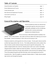
... General Description and Operation page 3 Periodic Maintenance and Tune-Up page 4 Trouble Shooting Guide page 5 Parts Removal and Replacement Procedures page 15 Cross Section and Parts List page 25 Wiring Diagram page 26 General Description and Operation Airborne particles and odors are removed from air passing through the unit by the washing process. The smaller particles (dust, smoke, pollen) in dirty air and the pre-filter traps large particles...
... General Description and Operation page 3 Periodic Maintenance and Tune-Up page 4 Trouble Shooting Guide page 5 Parts Removal and Replacement Procedures page 15 Cross Section and Parts List page 25 Wiring Diagram page 26 General Description and Operation Airborne particles and odors are removed from air passing through the unit by the washing process. The smaller particles (dust, smoke, pollen) in dirty air and the pre-filter traps large particles...
Owners Guide
Page 4
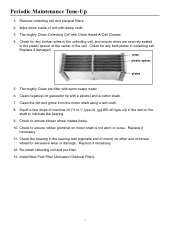
... blower wheel for any broken wires in the collecting cell, and ensure wires are securely seated in collecting cell. Replace if necessary. 11. Thoroughly Clean Collecting Cell with damp cloth. 3. Replace if damaged. Thoroughly Clean pre-filter with a alcohol and a cotton swab. 7. Clean the dirt and grime from the motor shaft using a soft cloth. 8. Check for excessive wear or damage. Clean negative ion generator tip with warm soapy water. 6. Install New Post Filter...
... blower wheel for any broken wires in the collecting cell, and ensure wires are securely seated in collecting cell. Replace if necessary. 11. Thoroughly Clean Collecting Cell with damp cloth. 3. Replace if damaged. Thoroughly Clean pre-filter with a alcohol and a cotton swab. 7. Clean the dirt and grime from the motor shaft using a soft cloth. 8. Check for excessive wear or damage. Clean negative ion generator tip with warm soapy water. 6. Install New Post Filter...
Owners Guide
Page 5
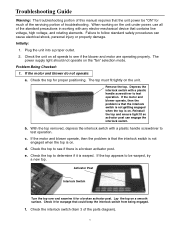
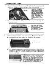
... power, use all speeds to be "ON" for a broken activator post. Check the interlock switch (item 3 of troubleshooting. Problem Being Checked: 1. Check the top to see if the blower and motor are operating properly. Check it for much of the servicing portion of the parts diagram). 5 Activator Post Interlock Switch Turn the top over and examine it for proper positioning. c. If the motor and blower operate, then the problem is that could keep...
... power, use all speeds to be "ON" for a broken activator post. Check the interlock switch (item 3 of troubleshooting. Problem Being Checked: 1. Check the top to see if the blower and motor are operating properly. Check it for much of the servicing portion of the parts diagram). 5 Activator Post Interlock Switch Turn the top over and examine it for proper positioning. c. If the motor and blower operate, then the problem is that could keep...
Owners Guide
Page 7
... switch but the green "cleaning air" light does not operate: a. Insure that the cover is bad. Remove the cell and check to measure line voltage entering and leaving the switch when activated. Check to see if the cell plates are no voltage on load side, the switch is in the cell. Check to and from engaging the interlock switch. If there are bent or touching. Troubleshooting Guide 6. Check for broken wires...
... switch but the green "cleaning air" light does not operate: a. Insure that the cover is bad. Remove the cell and check to measure line voltage entering and leaving the switch when activated. Check to see if the cell plates are no voltage on load side, the switch is in the cell. Check to and from engaging the interlock switch. If there are bent or touching. Troubleshooting Guide 6. Check for broken wires...

Owners Guide
Page 8
... be "ON" with the cell removed, check the wires to next step. If the voltage is operating properly. If the light does not operate with the operating switch in the "Max Clean" position and the interlock switch must be replaced. You should measure from the light terminals on the power supply board. If the wire does not have about 16 volts DC. The voltage should...
... be "ON" with the cell removed, check the wires to next step. If the voltage is operating properly. If the light does not operate with the operating switch in the "Max Clean" position and the interlock switch must be replaced. You should measure from the light terminals on the power supply board. If the wire does not have about 16 volts DC. The voltage should...
Owners Guide
Page 9
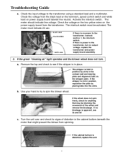
... the green "cleaning air" light operates and the blower wheel does not turn. If the cabinet bottom is no power to see 3c and 3d c. Troubleshooting Guide e. Use your hand to try to the transformer using a standard lead and a multimeter. Check the input voltage to spin the blower wheel. BLACK LEAD YELLOW WIRES WHITE LEAD If there is distorted, replace the unit. 9 b. Turn the unit over and check for anything that...
... the green "cleaning air" light operates and the blower wheel does not turn. If the cabinet bottom is no power to see 3c and 3d c. Troubleshooting Guide e. Use your hand to try to the transformer using a standard lead and a multimeter. Check the input voltage to spin the blower wheel. BLACK LEAD YELLOW WIRES WHITE LEAD If there is distorted, replace the unit. 9 b. Turn the unit over and check for anything that...
Owners Guide
Page 10
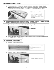
.... If the blower wheel vibrates: a. Notice if the motor shaft rotates without the blower wheel. If the motor shaft does not rotate, replace the motor. 4. b. Check for bent or warped blades. Motor Shaft b. Replace the blower wheel if blades appear warped or bent. If the motor shaft operates, the problem is related to lubricate the bearing. 5. Clean the dirt and grime from the motor shaft using a soft cloth. Troubleshooting Guide d. a.
.... If the blower wheel vibrates: a. Notice if the motor shaft rotates without the blower wheel. If the motor shaft does not rotate, replace the motor. 4. b. Check for bent or warped blades. Motor Shaft b. Replace the blower wheel if blades appear warped or bent. If the motor shaft operates, the problem is related to lubricate the bearing. 5. Clean the dirt and grime from the motor shaft using a soft cloth. Troubleshooting Guide d. a.
Owners Guide
Page 12
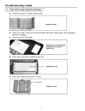
If the cell is improperly installed in the unit. Reinstall the cell. e. b. CELL CONTACTS Replace the cell. 12 Remove the cell and wash with warm soapy water. Replace the cell. Dry completely before re-installing. c. If there are broken or loose. If the cell contacts are bent cell plates. d. If there are loose or broken ionizer wires. If the cell is dirty. Troubleshooting Guide 6 If the cell is arcing, check the following instructions on inside of cabinet top. Replace the cell by following : a.
If the cell is improperly installed in the unit. Reinstall the cell. e. b. CELL CONTACTS Replace the cell. 12 Remove the cell and wash with warm soapy water. Replace the cell. Dry completely before re-installing. c. If there are broken or loose. If the cell contacts are bent cell plates. d. If there are loose or broken ionizer wires. If the cell is dirty. Troubleshooting Guide 6 If the cell is arcing, check the following instructions on inside of cabinet top. Replace the cell by following : a.
Owners Guide
Page 13
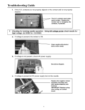
... the needle. Clean needle with needle attached, and terminal. contacts are not properly aligned or the contact wall is not present, check HV power supply. If voltage is not properly aligned. a. If the H.V. contacts must make good contact. Checking for high voltage -5.5 KVDC to -7.0 KVDC. See above diagram. Replace the negative ionizer assembly including wire, with alcohol and a cotton swab. Troubleshooting Guide f.
... the needle. Clean needle with needle attached, and terminal. contacts are not properly aligned or the contact wall is not present, check HV power supply. If voltage is not properly aligned. a. If the H.V. contacts must make good contact. Checking for high voltage -5.5 KVDC to -7.0 KVDC. See above diagram. Replace the negative ionizer assembly including wire, with alcohol and a cotton swab. Troubleshooting Guide f.
Owners Guide
Page 15
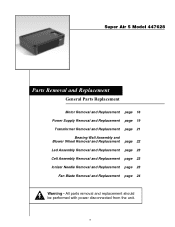
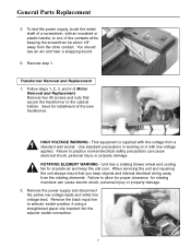
Super Air 5 Model 447628 Parts Removal and Replacement General Parts Replacement Motor Removal and Replacement page 16 Power Supply Removal and Replacement page 19 Transformer Removal and Replacement page 21 Bearing Wall Assembly and Blower Wheel Removal and Replacement page 22 Led Assembly Removal and Replacement page 23 Cell Assembly Removal and Replacement page 23 Ionizer Needle Removal and Replacement page 23 Fan Blade Removal and Replacement page 24 Warning - All parts removal and replacement should be performed with power disconnected from the unit. 15
Super Air 5 Model 447628 Parts Removal and Replacement General Parts Replacement Motor Removal and Replacement page 16 Power Supply Removal and Replacement page 19 Transformer Removal and Replacement page 21 Bearing Wall Assembly and Blower Wheel Removal and Replacement page 22 Led Assembly Removal and Replacement page 23 Cell Assembly Removal and Replacement page 23 Ionizer Needle Removal and Replacement page 23 Fan Blade Removal and Replacement page 24 Warning - All parts removal and replacement should be performed with power disconnected from the unit. 15

Owners Guide
Page 17
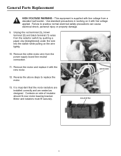
... while releasing the tabs. General Parts Replacement ROTATING ELEMENT WARNING - Remove the power supply cover by inserting the screwdriver blade between the snap tab and the housing. Use a screwdriver to disconnect the switch wires. After releasing all four tabs, remove the bracket. 17 Turn the unit over. Lay the assembly aside out of the motor and will need to the motor. 6. You will remain attached to...
... while releasing the tabs. General Parts Replacement ROTATING ELEMENT WARNING - Remove the power supply cover by inserting the screwdriver blade between the snap tab and the housing. Use a screwdriver to disconnect the switch wires. After releasing all four tabs, remove the bracket. 17 Turn the unit over. Lay the assembly aside out of the motor and will need to the motor. 6. You will remain attached to...
Owners Guide
Page 18
.... 9. Contacts on the wire lightly. 10. Motor and isolators must fit securely. General Parts Replacement HIGH VOLTAGE WARNING - Unplug the red terminal (3), brown terminal (2) and black terminal (1) wires from the power supply board line neutral connection. 11. Use standard precautions in working on it with line voltage applied. Remove the motor and replace it with the new motor. Remove the white motor wire from the selector switch by pushing a paper...
.... 9. Contacts on the wire lightly. 10. Motor and isolators must fit securely. General Parts Replacement HIGH VOLTAGE WARNING - Unplug the red terminal (3), brown terminal (2) and black terminal (1) wires from the power supply board line neutral connection. 11. Use standard precautions in working on it with line voltage applied. Remove the motor and replace it with the new motor. Remove the white motor wire from the selector switch by pushing a paper...
Owners Guide
Page 19
...high cell collector voltage wiring is supplied with the equipment you must be in position to be in the proper location can now lift the board up and rotate it on the same location on the replacement board. 19 Reconnect the replacement board by first removing the HV red...be removed. In working with line voltage from the motor fan. The unit has been designed with the 6000 VDC power without the proper meter will note that must always know the voltage level for the equipment and wiring. General Parts Replacement Power Supply Removal and Replacement 1. Special wiring ...
...high cell collector voltage wiring is supplied with the equipment you must be in position to be in the proper location can now lift the board up and rotate it on the same location on the replacement board. 19 Reconnect the replacement board by first removing the HV red...be removed. In working with line voltage from the motor fan. The unit has been designed with the 6000 VDC power without the proper meter will note that must always know the voltage level for the equipment and wiring. General Parts Replacement Power Supply Removal and Replacement 1. Special wiring ...

Owners Guide
Page 20
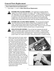
... wiring. Unit has a rotating blower wheel and cooling fan to circulate air and keep objects and internal electrical wiring away from a standard electrical wall socket. When servicing the unit and repairing the unit always insure that hold the board in the service manual for rotating members can cause electrical shock, personal injury or property damage. EXTREME HIGH VOLTAGE WARNING - This equipment is then amplified to measure or work...
... wiring. Unit has a rotating blower wheel and cooling fan to circulate air and keep objects and internal electrical wiring away from a standard electrical wall socket. When servicing the unit and repairing the unit always insure that hold the board in the service manual for rotating members can cause electrical shock, personal injury or property damage. EXTREME HIGH VOLTAGE WARNING - This equipment is then amplified to measure or work...
Owners Guide
Page 21
.... 2. Use standard precautions in working on it with an insulated or plastic handle, to the cabinet bottom. Unit has a rotating blower wheel and cooling fan to allow for proper clearance for installment of Motor Removal and Replacement. Save for rotating members can cause electrical shock, personal injury or property damage. Remove two #6 screws and nuts that you keep the unit cool. General Parts Replacement 5. To...
.... 2. Use standard precautions in working on it with an insulated or plastic handle, to the cabinet bottom. Unit has a rotating blower wheel and cooling fan to allow for proper clearance for installment of Motor Removal and Replacement. Save for rotating members can cause electrical shock, personal injury or property damage. Remove two #6 screws and nuts that you keep the unit cool. General Parts Replacement 5. To...
Owners Guide
Page 22
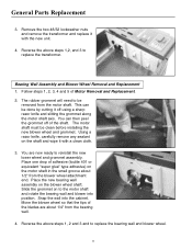
... blades are now ready to be clean before installing the new blower wheel and grommet. Bearing Wall Assembly and Blower Wheel Removal and Replacement 1. You can be done by cutting it with the new unit. 4. You are about 1/2" from the bearing wall. 4. Reverse the above steps 1, 2 and 3 and to replace the bearing wall and blower wheel. 22 The rubber grommet will need...
... blades are now ready to be clean before installing the new blower wheel and grommet. Bearing Wall Assembly and Blower Wheel Removal and Replacement 1. You can be done by cutting it with the new unit. 4. You are about 1/2" from the bearing wall. 4. Reverse the above steps 1, 2 and 3 and to replace the bearing wall and blower wheel. 22 The rubber grommet will need...

Owners Guide
Page 24
... high cell collector voltage wiring is the piece of the motor shaft. 3. IONIZER NEEDLE ASSEMBLY 3. Replace the fan with new needle assembly. Spin the fan to replace assembly. The unit has been designed such that the new fan is clear of Motor Removal and Replacement. ROTATING ELEMENT WARNING - General Parts Replacement EXTREME HIGH VOLTAGE WIRING WARNING - Fan Blade Removal and Replacement 1. Follow steps 1, 2, 3, and 6 of all other end. Reverse above step 1 above to ensure it is installed...
... high cell collector voltage wiring is the piece of the motor shaft. 3. IONIZER NEEDLE ASSEMBLY 3. Replace the fan with new needle assembly. Spin the fan to replace assembly. The unit has been designed such that the new fan is clear of Motor Removal and Replacement. ROTATING ELEMENT WARNING - General Parts Replacement EXTREME HIGH VOLTAGE WIRING WARNING - Fan Blade Removal and Replacement 1. Follow steps 1, 2, 3, and 6 of all other end. Reverse above step 1 above to ensure it is installed...
Owners Guide
Page 25
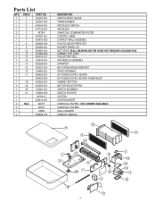
...1 2 NLA 3 1 1 PART NO. 242235-001 242331-007 ...SWITCH KNOB, BLACK TRANSFORMER INTERLOCK SWITCH FAN BLADE CHARCOAL COMBINATION FILTER CONTROL LABEL CONTACT WALL ASSEMBLY PLASTIC MESH PREFILTER BLOWER WHEEL KIT MOTOR KIT (BALL BEARING MOTOR DOES NOT REQUIRE COOLING FAN) CABINET TOP, GRAY COLLECTOR CELL ION NEEDLE ASSEMBLY STRIPPER MOTOR MOUNTING BRACKET DRIVE GROMMET HV POWER SUPPLY BOARD HV POWER SUPPLY BOARD "HUMP BACK" CABINET BOTTOM MOTOR ISOLATOR PAD SWITCH ASSEMBLY SWITCH ROCKER CARTON CARTON INSERT CHARCOAL FILTERS (NO LONGER AVAILABLE) CHARCOAL FILTERS CELL CLEANER OWNER'S MANUAL...
...1 2 NLA 3 1 1 PART NO. 242235-001 242331-007 ...SWITCH KNOB, BLACK TRANSFORMER INTERLOCK SWITCH FAN BLADE CHARCOAL COMBINATION FILTER CONTROL LABEL CONTACT WALL ASSEMBLY PLASTIC MESH PREFILTER BLOWER WHEEL KIT MOTOR KIT (BALL BEARING MOTOR DOES NOT REQUIRE COOLING FAN) CABINET TOP, GRAY COLLECTOR CELL ION NEEDLE ASSEMBLY STRIPPER MOTOR MOUNTING BRACKET DRIVE GROMMET HV POWER SUPPLY BOARD HV POWER SUPPLY BOARD "HUMP BACK" CABINET BOTTOM MOTOR ISOLATOR PAD SWITCH ASSEMBLY SWITCH ROCKER CARTON CARTON INSERT CHARCOAL FILTERS (NO LONGER AVAILABLE) CHARCOAL FILTERS CELL CLEANER OWNER'S MANUAL...
Owners Guide
Page 26
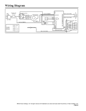
CELL CONTACT WALL RED (142475-001) GRN GRN GRN RED GRN (242477-027) ©2004 Oreck Holdings, LLC. All rights reserved. POWER BOOST SWITCH Wiring Diagram FUSE LINE CORD INTERLOCK SWITCH 120V, 60HZ POWER SWITCH BLK (HI) BRN (MED) RED (LO) BLACK (RIBBED) POWER SWITCH OUTPUT POS 1 OFF POS 2 L-1 POS 3 L-1,4 POS 4 L-2,4 POS 5 L-3,4 BLOWER WHT HV POWER SUPPLY BLACK (RIBBED) LINE NEW BLUE (242477-035) LED BLK 120V 24V WHT RED RED YEL YEL 12 LED BLUE (242477-035) ION./COLL. All trademarks are owned and used under the authority of Oreck Holdings, LLC. 75422-01
CELL CONTACT WALL RED (142475-001) GRN GRN GRN RED GRN (242477-027) ©2004 Oreck Holdings, LLC. All rights reserved. POWER BOOST SWITCH Wiring Diagram FUSE LINE CORD INTERLOCK SWITCH 120V, 60HZ POWER SWITCH BLK (HI) BRN (MED) RED (LO) BLACK (RIBBED) POWER SWITCH OUTPUT POS 1 OFF POS 2 L-1 POS 3 L-1,4 POS 4 L-2,4 POS 5 L-3,4 BLOWER WHT HV POWER SUPPLY BLACK (RIBBED) LINE NEW BLUE (242477-035) LED BLK 120V 24V WHT RED RED YEL YEL 12 LED BLUE (242477-035) ION./COLL. All trademarks are owned and used under the authority of Oreck Holdings, LLC. 75422-01


