Owner Manual
Page 4
...Front panel display 11 Remote controller 12 Connections 14 TX-SR701/701E 15 TX-SR601/601E 15 Connecting your audio components 16 Connecting your video components 17 12V TRIGGER ZONE 2 terminal 21 PRE OUT (TX-SR701/701E only 21 Operating components not reached by the remote controller signals (IR IN...turning off the sound 45 Listening Modes 46 Selecting a listening mode (TX-SR701/701E 48 Re-EQ function for movies (TX-SR701/701E only) ......49 Selecting a listening mode (TX-SR601/601E 50 Original filter (CinemaFILTER) loading for movies (TX-SR601/601E only 51 Input Setup 52 ...
...Front panel display 11 Remote controller 12 Connections 14 TX-SR701/701E 15 TX-SR601/601E 15 Connecting your audio components 16 Connecting your video components 17 12V TRIGGER ZONE 2 terminal 21 PRE OUT (TX-SR701/701E only 21 Operating components not reached by the remote controller signals (IR IN...turning off the sound 45 Listening Modes 46 Selecting a listening mode (TX-SR701/701E 48 Re-EQ function for movies (TX-SR701/701E only) ......49 Selecting a listening mode (TX-SR601/601E 50 Original filter (CinemaFILTER) loading for movies (TX-SR601/601E only 51 Input Setup 52 ...

Owner Manual
Page 6
...mode-key LEDs I 12V Trigger output for Zone 2 I IR input terminal • *Manufactured under license from Dolby Laboratories. Features TX-SR701/701E Amplifier Features I 100 W × 2 (Front)/ 100 W (Center)/ 100 W × 2 (Surround)/...Select certified I THX surround EX® I Dolby®* Digital, Dolby Digital EX, Dolby Pro Logic II I DTS, DTS 96/24, DTS-ES Extended Surround, DTS Neo:6 I Non-Scaling Configuration I Re-EQ I Pure Audio Mode I Crossover Adjustment (40/60/80/100/120/150 Hz) I Onscreen graphical displays I Digital Outputs (1 coaxial, 1 optical) I 2 component...
...mode-key LEDs I 12V Trigger output for Zone 2 I IR input terminal • *Manufactured under license from Dolby Laboratories. Features TX-SR701/701E Amplifier Features I 100 W × 2 (Front)/ 100 W (Center)/ 100 W × 2 (Surround)/...Select certified I THX surround EX® I Dolby®* Digital, Dolby Digital EX, Dolby Pro Logic II I DTS, DTS 96/24, DTS-ES Extended Surround, DTS Neo:6 I Non-Scaling Configuration I Re-EQ I Pure Audio Mode I Crossover Adjustment (40/60/80/100/120/150 Hz) I Onscreen graphical displays I Digital Outputs (1 coaxial, 1 optical) I 2 component...

Owner Manual
Page 7
...before plugging in the same room or using this unit Conversion plug × 1 (Use this switch to avoid damage from the remote controller. ANTENNA AM COMPONENT VIDEO INPUT 2 INPUT 1 OUTPUT Y PB FM 75 ZONE 2 LINE OUT L ZONE 2 SPEAKERS L CAUTION: SPEAKER IMPEDANCE 6 OHMS MIN. /SPEAKER ...DIGITAL IN OUT OPTICAL 2 1 OPTICAL COAXIAL VIDEO 3 IN VIDEO 2 OUT IN IN GND L IN COAXIAL IN OUT IN IN OUT IN R VIDEO 1 OUT IN DVD IN REMOTE R CONTROL MONITOR OUT V ZONE 2 12 V TRIGGER OUT R ZONE 2 FRONT S IR IN L AV RECEIVER MODEL NO. Remote control sensor TX-SR701...
...before plugging in the same room or using this unit Conversion plug × 1 (Use this switch to avoid damage from the remote controller. ANTENNA AM COMPONENT VIDEO INPUT 2 INPUT 1 OUTPUT Y PB FM 75 ZONE 2 LINE OUT L ZONE 2 SPEAKERS L CAUTION: SPEAKER IMPEDANCE 6 OHMS MIN. /SPEAKER ...DIGITAL IN OUT OPTICAL 2 1 OPTICAL COAXIAL VIDEO 3 IN VIDEO 2 OUT IN IN GND L IN COAXIAL IN OUT IN IN OUT IN R VIDEO 1 OUT IN DVD IN REMOTE R CONTROL MONITOR OUT V ZONE 2 12 V TRIGGER OUT R ZONE 2 FRONT S IR IN L AV RECEIVER MODEL NO. Remote control sensor TX-SR701...
Owner Manual
Page 10
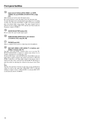
...zone is turned off the output, press the OFF button. When the ZONE 2 indicator is off, then either output to select the input source. DIRECT/PURE AUDIO button and indicator (TX-SR701/701E only) [46, 48] PHONES jack [44] This is output to ZONE 2. To turn off or Rec Out ... is a standard stereo jack for recording (Rec Out). Press these buttons to select the type of audio input signal. The ZONE 2 indicator lights when a signal is automatically fixed to another component for connecting stereo headphones. Note: The Rec Out and Zone 2 buttons use the TXSR701/701E/601/...
...zone is turned off the output, press the OFF button. When the ZONE 2 indicator is off, then either output to select the input source. DIRECT/PURE AUDIO button and indicator (TX-SR701/701E only) [46, 48] PHONES jack [44] This is output to ZONE 2. To turn off or Rec Out ... is a standard stereo jack for recording (Rec Out). Press these buttons to select the type of audio input signal. The ZONE 2 indicator lights when a signal is automatically fixed to another component for connecting stereo headphones. Note: The Rec Out and Zone 2 buttons use the TXSR701/701E/601/...

Owner Manual
Page 11
...function is received in the stereo mode. AUTO indicator Lights when receiving FM broadcasts in stereo. However, does not show the format of the listening mode indicators lights to show the source format when the FM or AM source is selected. Listening mode or digital input ... 2 indicator Lights when using the remote zone (Zone 2). In addition, one component to preset a radio station. When the FM or AM input is received. Tuning indicators TUNED indicator Lights when a radio station is selected, shows the frequency and preset number. RDS indicator (European models only) Lights ...
...function is received in the stereo mode. AUTO indicator Lights when receiving FM broadcasts in stereo. However, does not show the format of the listening mode indicators lights to show the source format when the FM or AM source is selected. Listening mode or digital input ... 2 indicator Lights when using the remote zone (Zone 2). In addition, one component to preset a radio station. When the FM or AM input is received. Tuning indicators TUNED indicator Lights when a radio station is selected, shows the frequency and preset number. RDS indicator (European models only) Lights ...
Owner Manual
Page 12
... the macro function. MACRO 1, 2 button [73] Press to turn on the TX-SR701/701E/601/601E. The selected MODE button will light for the tuner (CH). [38] When the CD mode is selected, also press to select a disc when operating components with multiple angle playback. RETURN button [32] Press to enter the...setting changes from "Auto" to "Multich" (only if DVD is selected as the input source) to "Analog" and back each time this button is pressed, it will also light whenever any other Onkyo components connected to place the TX-SR701/701E/601/601E in standby and does not turn off . The SLEEP...
... the macro function. MACRO 1, 2 button [73] Press to turn on the TX-SR701/701E/601/601E. The selected MODE button will light for the tuner (CH). [38] When the CD mode is selected, also press to select a disc when operating components with multiple angle playback. RETURN button [32] Press to enter the...setting changes from "Auto" to "Multich" (only if DVD is selected as the input source) to "Analog" and back each time this button is pressed, it will also light whenever any other Onkyo components connected to place the TX-SR701/701E/601/601E in standby and does not turn off . The SLEEP...

Owner Manual
Page 14
... to the instructions that came with power cords and speaker cables. Improper connection Inserted completely • Do not bind audio/video connection cables with the component that you are connecting. • Do not plug in the power cord until all connections have been properly made. • For input jacks, ... (marked V) are depicted in noise, poor performance, or damage to the equipment. Left (white) Right (red) L Audio connection cable R PR PR PB PB Component video connection cable Y Y Video connection cable S video connection cable Coaxial cable Optical cable 14
... to the instructions that came with power cords and speaker cables. Improper connection Inserted completely • Do not bind audio/video connection cables with the component that you are connecting. • Do not plug in the power cord until all connections have been properly made. • For input jacks, ... (marked V) are depicted in noise, poor performance, or damage to the equipment. Left (white) Right (red) L Audio connection cable R PR PR PB PB Component video connection cable Y Y Video connection cable S video connection cable Coaxial cable Optical cable 14
Owner Manual
Page 15
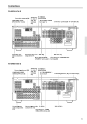
...Connections TX-SR701/701E Connecting antennas [29] COMPONENT VIDEO INPUT/OUTPUT [18-20] When using the ZONE 2 SPEAKERS terminals [23] PRE OUT [21] 15 SUB WOOFER R AV RECEIVER MODEL NO. AV RECEIVER MODEL NO. TX-SR 601E Connecting your audio components [16] Connecting your video IR IN [22] components [17... ZONE 2 terminals terminal [21] [23] Connecting speakers [26] AC OUTLETS [24] ANTENNA AM COMPONENT VIDEO INPUT 2 INPUT 1 OUTPUT Y PB FM 75 ZONE 2 LINE OUT L ZONE 2 SPEAKERS L PR DIGITAL IN OUT OPTICAL 2 1 OPTICAL VIDEO 3 COAXIAL IN VIDEO 2 OUT IN IN GND L IN...
...Connections TX-SR701/701E Connecting antennas [29] COMPONENT VIDEO INPUT/OUTPUT [18-20] When using the ZONE 2 SPEAKERS terminals [23] PRE OUT [21] 15 SUB WOOFER R AV RECEIVER MODEL NO. AV RECEIVER MODEL NO. TX-SR 601E Connecting your audio components [16] Connecting your video IR IN [22] components [17... ZONE 2 terminals terminal [21] [23] Connecting speakers [26] AC OUTLETS [24] ANTENNA AM COMPONENT VIDEO INPUT 2 INPUT 1 OUTPUT Y PB FM 75 ZONE 2 LINE OUT L ZONE 2 SPEAKERS L PR DIGITAL IN OUT OPTICAL 2 1 OPTICAL VIDEO 3 COAXIAL IN VIDEO 2 OUT IN IN GND L IN...
Owner Manual
Page 16
...is an explanation of typical ways to connect various components to the PHONO audio jacks of the TX-SR701/701E. There are many ways that the connection to the DIGITAL IN jack. The audio inputs and outputs require RCA-type connectors. To the digital inputs, connect CD players, LD players, DVD ...If the compact disc player has a digital output, connect it to make sure that any one component can connect your audio components Below is up to you can be sure to either the DIGITAL IN COAXIAL jack or the DIGITAL IN OPTICAL jack of the TX-SR701/ 701E/601/601E depending on the compact...
...is an explanation of typical ways to connect various components to the PHONO audio jacks of the TX-SR701/701E. There are many ways that the connection to the DIGITAL IN jack. The audio inputs and outputs require RCA-type connectors. To the digital inputs, connect CD players, LD players, DVD ...If the compact disc player has a digital output, connect it to make sure that any one component can connect your audio components Below is up to you can be sure to either the DIGITAL IN COAXIAL jack or the DIGITAL IN OPTICAL jack of the TX-SR701/ 701E/601/601E depending on the compact...
Owner Manual
Page 17
...) Analog audio output (surround L/R) R (red) L (white) Analog audio output (front L/R) R (red) Digital audio output (optical) Connecting your video components to VIDEO 3). • The VIDEO 4 inputs are recommended to match the type of component video output connectors for connection between video devices (ex. TX-SR701/701E/601/601E also has one bank of video terminals for...
...) Analog audio output (surround L/R) R (red) L (white) Analog audio output (front L/R) R (red) Digital audio output (optical) Connecting your video components to VIDEO 3). • The VIDEO 4 inputs are recommended to match the type of component video output connectors for connection between video devices (ex. TX-SR701/701E/601/601E also has one bank of video terminals for...

Owner Manual
Page 18
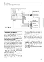
... Signal flow 4. With the initial settings of connector on the TX-SR701/ 701E/601/601E. If the device has a digital output, connect it to the COMPONENT VIDEO INPUT 1 or 2 jacks on the DVD player. If the digital connection is set for the COMPONENT VIDEO INPUT 1 jacks. Note: If the DVD player has both...cable, connect the audio output jacks of the DVD player to the DVD V IN jack of the TX-SR701/701E/601/601E, the DVD input source is set for digital input at "Input Setup" → "Component Video" (see page 52). Connecting a DVD player (DVD) Using an RCA video cable, connect...
... Signal flow 4. With the initial settings of connector on the TX-SR701/ 701E/601/601E. If the device has a digital output, connect it to the COMPONENT VIDEO INPUT 1 or 2 jacks on the DVD player. If the digital connection is set for the COMPONENT VIDEO INPUT 1 jacks. Note: If the DVD player has both...cable, connect the audio output jacks of the DVD player to the DVD V IN jack of the TX-SR701/701E/601/601E, the DVD input source is set for digital input at "Input Setup" → "Component Video" (see page 52). Connecting a DVD player (DVD) Using an RCA video cable, connect...
Owner Manual
Page 19
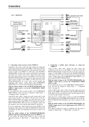
... input jack of the video cassette recorder to either the DIGITAL IN COAXIAL jack or the DIGITAL IN OPTICAL jack of the TXSR701/701E/601/601E depending on the TX-SR701/701E/601/601E. Or if the video cassette recorder has component video outputs, connect them to the R jack. Make ... 2 jacks. With the initial settings of the TX-SR701/ 701E/601/601E. Or if the device has component video outputs, connect them to the VIDEO 1 V OUT jack of the TX-SR701/701E/601/601E, the VIDEO 1 input source is allocated as the digital input source for digital input at the OPTICAL 2 jack (OPT 2). ...
... input jack of the video cassette recorder to either the DIGITAL IN COAXIAL jack or the DIGITAL IN OPTICAL jack of the TXSR701/701E/601/601E depending on the TX-SR701/701E/601/601E. Or if the video cassette recorder has component video outputs, connect them to the R jack. Make ... 2 jacks. With the initial settings of the TX-SR701/ 701E/601/601E. Or if the device has component video outputs, connect them to the VIDEO 1 V OUT jack of the TX-SR701/701E/601/601E, the VIDEO 1 input source is allocated as the digital input source for digital input at the OPTICAL 2 jack (OPT 2). ...

Owner Manual
Page 20
...unnecessary to the VIDEO 2 OUT audio jacks of the TX-SR701/ 701E/601/601E. Or if the device has component video outputs, connect them to the DIGITAL OUTPUT jack of the TX-SR701/701E/601/601E for digital recording of the signal from the digital input of the TX-SR701/701E/ 601/601E using S video cables, connect ... jack of the device to the VIDEO 2 S OUT jack of the TX-SR701/701E/601/601E. If you connect the digital audio output, be sure to the MONITOR OUT V jack of COMPONENT VIDEO OUTPUT jacks on the TX-SR701/701E/601/601E. Using an RCA video cable, connect the video input jack...
...unnecessary to the VIDEO 2 OUT audio jacks of the TX-SR701/ 701E/601/601E. Or if the device has component video outputs, connect them to the DIGITAL OUTPUT jack of the TX-SR701/701E/601/601E for digital recording of the signal from the digital input of the TX-SR701/701E/ 601/601E using S video cables, connect ... jack of the device to the VIDEO 2 S OUT jack of the TX-SR701/701E/601/601E. If you connect the digital audio output, be sure to the MONITOR OUT V jack of COMPONENT VIDEO OUTPUT jacks on the TX-SR701/701E/601/601E. Using an RCA video cable, connect the video input jack...
Owner Manual
Page 22
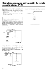
...The diagram below . With this connection, select "Main" at "Hardware Config" → "IR IN Position" (see page 55). IR IN TX-SR701/701E/ 601/601E Connecting block IR Receiver Remote Controller Main room Zone 2 room : Signal flow 22 Operating components not reached by the remote controller signals ... may be on the other side of the building from the main zone. Make the connections as those given below: • Onkyo's Multi-Room System kit (IR Remote Controller Extension System) • Multiroom A/V distribution and control system such as shown below shows...
...The diagram below . With this connection, select "Main" at "Hardware Config" → "IR IN Position" (see page 55). IR IN TX-SR701/701E/ 601/601E Connecting block IR Receiver Remote Controller Main room Zone 2 room : Signal flow 22 Operating components not reached by the remote controller signals ... may be on the other side of the building from the main zone. Make the connections as those given below: • Onkyo's Multi-Room System kit (IR Remote Controller Extension System) • Multiroom A/V distribution and control system such as shown below shows...

Owner Manual
Page 24
... can be operated by the remote controller supplied with the remote controller without connecting the terminals (see page 43). The other Onkyo components equipped with the TX-SR701/701E/601/601E. Dimmer function The Dimmer function (display brightness adjustment) of the TXSR701/701E/601/601E can be used to...120V 60 Hz SWITCHED TOTAL 120W 1A MAX. Direct change function When the play button is pressed at an -connected component, the input source selected at the TX-SR701/ 701E/601/601E automatically switches to that is printed on the area of the AC outlets may differ depending on ...
... can be operated by the remote controller supplied with the remote controller without connecting the terminals (see page 43). The other Onkyo components equipped with the TX-SR701/701E/601/601E. Dimmer function The Dimmer function (display brightness adjustment) of the TXSR701/701E/601/601E can be used to...120V 60 Hz SWITCHED TOTAL 120W 1A MAX. Direct change function When the play button is pressed at an -connected component, the input source selected at the TX-SR701/ 701E/601/601E automatically switches to that is printed on the area of the AC outlets may differ depending on ...
Owner Manual
Page 27
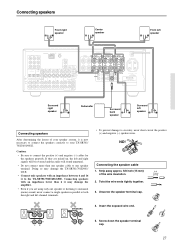
... correctly to both the right and left speaker ANTENNA AM COMPONENT VIDEO INPUT 2 INPUT 1 OUTPUT Y PB FM 75 ZONE 2 LINE OUT L ZONE 2 SPEAKERS L PR DIGITAL IN OUT OPTICAL 2 1 OPTICAL VIDEO 3 COAXIAL IN VIDEO...TX-SR701/701E/601/601E. Doing so may damage the amplifier. • Even if you are mixed up, the left speaker Connecting speakers After determining the layout of the wire insulation. 2. R + SPEAKERS -+ L L R - Unscrew the speaker terminal cap. 5/8" (15mm) SPEAKERS -+ L L R - Screw down the speaker terminal cap. 27 SUB WOOFER R AV RECEIVER...
... correctly to both the right and left speaker ANTENNA AM COMPONENT VIDEO INPUT 2 INPUT 1 OUTPUT Y PB FM 75 ZONE 2 LINE OUT L ZONE 2 SPEAKERS L PR DIGITAL IN OUT OPTICAL 2 1 OPTICAL VIDEO 3 COAXIAL IN VIDEO...TX-SR701/701E/601/601E. Doing so may damage the amplifier. • Even if you are mixed up, the left speaker Connecting speakers After determining the layout of the wire insulation. 2. R + SPEAKERS -+ L L R - Unscrew the speaker terminal cap. 5/8" (15mm) SPEAKERS -+ L L R - Screw down the speaker terminal cap. 27 SUB WOOFER R AV RECEIVER...

Owner Manual
Page 41
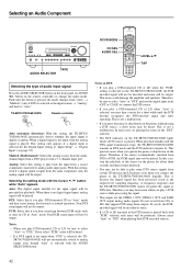
...the VOL buttons on the display. Selecting an Audio Component TX-SR701/701E STANDBY/ON AUDIO ADJUST SETUP RETURN TUNI NG MASTER VOLUME POWER ON OFF REC OUT ZONE 2 OFF LEVEL STANDBY DISPLAY RT/PTY/TP STEREO LISTENING MODE SURROUND THX DSP PRESET MEMORY FM MODE CLEAR...Input source buttons RCVR MODE VOL INPUT SELECTOR buttons Basic operation If you have selected, see "Digital Input" on page 52. Adjust the volume to the TX-SR701/701E/601/601E together. Start playing the selected input source. Press the desired input source. See "Enjoying DVD multichannel audio ...
...the VOL buttons on the display. Selecting an Audio Component TX-SR701/701E STANDBY/ON AUDIO ADJUST SETUP RETURN TUNI NG MASTER VOLUME POWER ON OFF REC OUT ZONE 2 OFF LEVEL STANDBY DISPLAY RT/PTY/TP STEREO LISTENING MODE SURROUND THX DSP PRESET MEMORY FM MODE CLEAR...Input source buttons RCVR MODE VOL INPUT SELECTOR buttons Basic operation If you have selected, see "Digital Input" on page 52. Adjust the volume to the TX-SR701/701E/601/601E together. Start playing the selected input source. Press the desired input source. See "Enjoying DVD multichannel audio ...
Owner Manual
Page 42
... analog signal is no digital signal input, analog signal will not be output. Analog: Select this setting to play back the input from a source component connected to "Auto." When there is played. Non-PCM sound input will be played. When playback finishes and the DTS signal transmission stops, the TX-SR701/701E/601/601E...
... analog signal is no digital signal input, analog signal will not be output. Analog: Select this setting to play back the input from a source component connected to "Auto." When there is played. Non-PCM sound input will be played. When playback finishes and the DTS signal transmission stops, the TX-SR701/701E/601/601E...
Owner Manual
Page 43
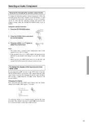
Selecting an Audio Component Temporarily changing the speaker output levels To change the display of the... the TXSR701/701E/601/601E, you set to allow system functions for a connected Onkyo cassette tape or MD recorder. 43 Press the CH SEL button and select the desired speaker. 3. Press the LEVEL or button to MD (approx. 3 ...seconds). By changing the display, when an Onkyo MD recorder is set the level, the current level will become enabled. TAPE To return the display to the original settings when the TX-SR701...
Selecting an Audio Component Temporarily changing the speaker output levels To change the display of the... the TXSR701/701E/601/601E, you set to allow system functions for a connected Onkyo cassette tape or MD recorder. 43 Press the CH SEL button and select the desired speaker. 3. Press the LEVEL or button to MD (approx. 3 ...seconds). By changing the display, when an Onkyo MD recorder is set the level, the current level will become enabled. TAPE To return the display to the original settings when the TX-SR701...
Owner Manual
Page 44
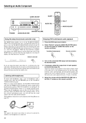
...off at the listening position. Adjust the volume with the MASTER VOLUME dial or the VOL buttons on the TX-SR701/ 701E/601/601E front panel. Selecting an Audio Component AUDIO ADJUST SLEEP STANDBY/ON AUDIO ADJUST SETUP RETURN TUNI NG MASTER VOLUME POWER ON OFF REC OUT ZONE... STANDBY DISPLAY RT/PTY/TP STEREO LISTENING MODE SURROUND THX DSP PRESET MEMORY FM MODE CLEAR PHONES DIRECT/ PURE AUDIO PURE AUDIO AUDIO SELECTOR DVD VIDEO 1 VIDEO 2 VIDEO 3 VIDEO 4 VCR 1 VCR 2 TAPE TUNER CD PHONO ENTER VIDEO 4 INPUT DIGITAL S VIDEO VIDEO L AUDIO R AUDIO SEL PHONES...
...off at the listening position. Adjust the volume with the MASTER VOLUME dial or the VOL buttons on the TX-SR701/ 701E/601/601E front panel. Selecting an Audio Component AUDIO ADJUST SLEEP STANDBY/ON AUDIO ADJUST SETUP RETURN TUNI NG MASTER VOLUME POWER ON OFF REC OUT ZONE... STANDBY DISPLAY RT/PTY/TP STEREO LISTENING MODE SURROUND THX DSP PRESET MEMORY FM MODE CLEAR PHONES DIRECT/ PURE AUDIO PURE AUDIO AUDIO SELECTOR DVD VIDEO 1 VIDEO 2 VIDEO 3 VIDEO 4 VCR 1 VCR 2 TAPE TUNER CD PHONO ENTER VIDEO 4 INPUT DIGITAL S VIDEO VIDEO L AUDIO R AUDIO SEL PHONES...


