Owner Manual
Page 4
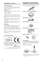
... the following accessories: Remote controller & two batteries (AA/R6) Speaker setup microphone Indoor FM antenna AM loop antenna 1 2 3 Speaker Cable Speaker cable labels * Power-plug adapter Only supplied in certain countries. Fit...of this adapter if your AC outlet does not match with the plug on the AV receiver's power cord (adapter varies from country to country). *How to mount the AC plug... K. IMPORTANT The plug is not suitable for the ASTA mark or the BSI mark on the plug. MIYAGI ONKYO EUROPE ELECTRONICS GmbH Front Left Front Left SP-B / Zone 2 Left SP-B / Zone 2 Left Front Right...
... the following accessories: Remote controller & two batteries (AA/R6) Speaker setup microphone Indoor FM antenna AM loop antenna 1 2 3 Speaker Cable Speaker cable labels * Power-plug adapter Only supplied in certain countries. Fit...of this adapter if your AC outlet does not match with the plug on the AV receiver's power cord (adapter varies from country to country). *How to mount the AC plug... K. IMPORTANT The plug is not suitable for the ASTA mark or the BSI mark on the plug. MIYAGI ONKYO EUROPE ELECTRONICS GmbH Front Left Front Left SP-B / Zone 2 Left SP-B / Zone 2 Left Front Right...
Owner Manual
Page 5
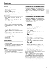
... TX-SR674/674E and TX-SR8467 Only • 95 watts per channel into 8 ohms, 20 Hz to 20 kHz, less than 0.08% total harmonic distortion (FTC rating) • VLSC*8 (Vector Linear Shaping Circuitry) on the front left and right channels *1. VLSC is a registered trademark of Onkyo ... Audio Corporation. Features Amplifier • 7-channel amplifier • Optimum Gain Volume Circuitry • Zone 2 capability • 24-bit/192 kHz D/A converters • WRAT (Wide Range Amplifier Technology) • Color-coded speaker terminal posts Audio/Video • Dolby*1 Digital,...
... TX-SR674/674E and TX-SR8467 Only • 95 watts per channel into 8 ohms, 20 Hz to 20 kHz, less than 0.08% total harmonic distortion (FTC rating) • VLSC*8 (Vector Linear Shaping Circuitry) on the front left and right channels *1. VLSC is a registered trademark of Onkyo ... Audio Corporation. Features Amplifier • 7-channel amplifier • Optimum Gain Volume Circuitry • Zone 2 capability • 24-bit/192 kHz D/A converters • WRAT (Wide Range Amplifier Technology) • Color-coded speaker terminal posts Audio/Video • Dolby*1 Digital,...
Owner Manual
Page 6
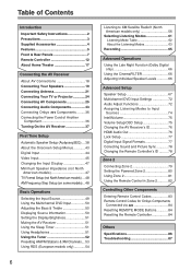
... Projector 24 Connecting AV Components 25 Connecting Audio Components 33 Connecting Onkyo Components .........36 Connecting the Power Cord of Another Component 36 Turning On the AV Receiver 37 First Time Setup Automatic Speaker Setup (Audyssey2EQ)....38 About the Onscreen Setup Menus............43 Digital Input...50 Displaying Source Information 50 Setting the Display Brightness 51 Muting the AV Receiver 51 Using the Sleep Timer 51 Using Headphones 51 Using the Tuner 52 Presetting AM/FM Stations & XM Channels....53 Using RDS (European models only 54 6 Listening to XM Satellite Radio...
... Projector 24 Connecting AV Components 25 Connecting Audio Components 33 Connecting Onkyo Components .........36 Connecting the Power Cord of Another Component 36 Turning On the AV Receiver 37 First Time Setup Automatic Speaker Setup (Audyssey2EQ)....38 About the Onscreen Setup Menus............43 Digital Input...50 Displaying Source Information 50 Setting the Display Brightness 51 Muting the AV Receiver 51 Using the Sleep Timer 51 Using Headphones 51 Using the Tuner 52 Presetting AM/FM Stations & XM Channels....53 Using RDS (European models only 54 6 Listening to XM Satellite Radio...
Owner Manual
Page 8
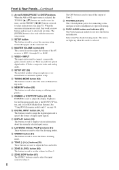
... is used to select the Stereo listening mode. T TONE, [-] & [+] buttons (50) These buttons are used to turn off the output of the AV receiver to select radio presets (see page 53). V ZONE 2/OFF button (81) The ZONE 2 button is used to MIN, 1 through 99, or MAX. ... listening. N MEMORY button (53) This button is used to access the onscreen setup menus that appear on the connected TV. L SETUP MIC (38) The included speaker setup microphone is selected, the TUNING [ ] [ ] buttons are used to tune the tuner, and the PRESET [ ] [ ] buttons are jacks for optical digital ...
... is used to select the Stereo listening mode. T TONE, [-] & [+] buttons (50) These buttons are used to turn off the output of the AV receiver to select radio presets (see page 53). V ZONE 2/OFF button (81) The ZONE 2 button is used to MIN, 1 through 99, or MAX. ... listening. N MEMORY button (53) This button is used to access the onscreen setup menus that appear on the connected TV. L SETUP MIC (38) The included speaker setup microphone is selected, the TUNING [ ] [ ] buttons are used to tune the tuner, and the PRESET [ ] [ ] buttons are jacks for optical digital ...
Owner Manual
Page 10
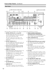
... FRONT, CENTER, SURROUND & SURROUND BACK SPEAKERS (20) These terminal posts are for connecting an AM antenna. The HDMI inputs are for connecting your AV receiver. E AM ANTENNA (21) These push terminals are for connecting speakers in parentheses show where you purchased your front..., center, surround, and surround back speakers. F FM ANTENNA (21) This jack is obstructed, a commercially available IR receiver can be connected here....
... FRONT, CENTER, SURROUND & SURROUND BACK SPEAKERS (20) These terminal posts are for connecting an AM antenna. The HDMI inputs are for connecting your AV receiver. E AM ANTENNA (21) These push terminals are for connecting speakers in parentheses show where you purchased your front..., center, surround, and surround back speakers. F FM ANTENNA (21) This jack is obstructed, a commercially available IR receiver can be connected here....
Owner Manual
Page 14
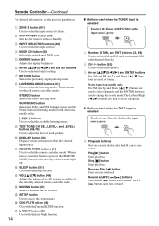
...(13) Used to On or Standby. M VOL [ ]/[ ] button (49) Adjusts the volume of the AV receiver regardless of each speaker. N MUTING button (51) Mutes or unmutes the AV receiver. button (53) Used to adjust the level of the currently selected remote controller mode. I TEST TONE, CH SEL...menus. Q L NIGHT button (66) Used with the Late Night function. 14 I Buttons used to select AM and FM radio stations and XM radio channels directly. 2 CH +/- Play [ ] button Starts playback. These buttons work in parentheses. G RETURN button Selects the previously displayed setup menu. E ...
...(13) Used to On or Standby. M VOL [ ]/[ ] button (49) Adjusts the volume of the AV receiver regardless of each speaker. N MUTING button (51) Mutes or unmutes the AV receiver. button (53) Used to adjust the level of the currently selected remote controller mode. I TEST TONE, CH SEL...menus. Q L NIGHT button (66) Used with the Late Night function. 14 I Buttons used to select AM and FM radio stations and XM radio channels directly. 2 CH +/- Play [ ] button Starts playback. These buttons work in parentheses. G RETURN button Selects the previously displayed setup menu. E ...
Owner Manual
Page 17
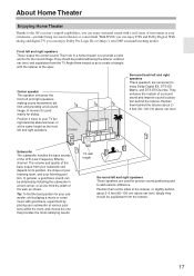
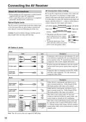
...its position, the shape of the LFE (Low-Frequency Effects) channel. Their role in a movie theater or concert hall. They ...speakers are necessary to enjoy Dolby Digital EX, DTS-ES Matrix, and DTS-ES Discrete. Position them inward so as shown. Angle them behind the listener. Subwoofer The subwoofer handles the bass sounds of your listening room, and your listening position. With DVDs you can enjoy Dolby Pro Logic IIx or Onkyo... About Home Theater Enjoying Home Theater Thanks to the AV receiver's superb capabilities, you can be obtained by placing your subwoofer...
...its position, the shape of the LFE (Low-Frequency Effects) channel. Their role in a movie theater or concert hall. They ...speakers are necessary to enjoy Dolby Digital EX, DTS-ES Matrix, and DTS-ES Discrete. Position them inward so as shown. Angle them behind the listener. Subwoofer The subwoofer handles the bass sounds of your listening room, and your listening position. With DVDs you can enjoy Dolby Pro Logic IIx or Onkyo... About Home Theater Enjoying Home Theater Thanks to the AV receiver's superb capabilities, you can be obtained by placing your subwoofer...
Owner Manual
Page 18
... audio, and R can cause noise or malfunctions). • To prevent interference, keep audio and video cables away from power cords and speaker cables. Use white plugs to make good connections (loose connections can be used on virtually all the way. The audio quality is the ...the best sound quality and allows you 've completed and double-checked all the way to connect left-channel audio inputs and outputs (typically labeled "L"). Optical Digital Jacks The AV receiver's optical digital jacks have shutter-type covers that open when an optical plug is commonly used instead of...
... audio, and R can cause noise or malfunctions). • To prevent interference, keep audio and video cables away from power cords and speaker cables. Use white plugs to make good connections (loose connections can be used on virtually all the way. The audio quality is the ...the best sound quality and allows you 've completed and double-checked all the way to connect left-channel audio inputs and outputs (typically labeled "L"). Optical Digital Jacks The AV receiver's optical digital jacks have shutter-type covers that open when an optical plug is commonly used instead of...
Owner Manual
Page 19
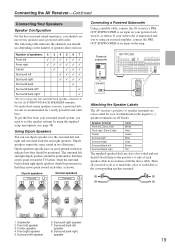
... LINE INPUT PRE OUT SUB WOOFER Attaching the Speaker Labels The AV receiver's positive (+) speaker terminals are color-coded for a really powerful and solid bass. Surround left speaker 8. Surround back right speaker 19 If your subwoofer is unpowered and you ... Gray Surround back left speaker 3. Front right speaker 5. Surround back left speaker 6. Subwoofer 2. No matter how many speakers you should connect seven speakers and a powered subwoofer. Dipole speakers typically have . The following table indicates the channels you use dipole speakers for the surround left...
... LINE INPUT PRE OUT SUB WOOFER Attaching the Speaker Labels The AV receiver's positive (+) speaker terminals are color-coded for a really powerful and solid bass. Surround left speaker 8. Surround back right speaker 19 If your subwoofer is unpowered and you ... Gray Surround back left speaker 3. Front right speaker 5. Surround back left speaker 6. Subwoofer 2. No matter how many speakers you should connect seven speakers and a powered subwoofer. Dipole speakers typically have . The following table indicates the channels you use dipole speakers for the surround left...
Owner Manual
Page 20
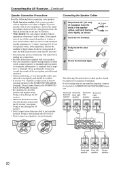
... the amplifier at high volume levels for a long period of time, the built-in protection circuit may damage the AV receiver. • Don't connect one surround back speaker, connect it to short the positive and negative wires. Do not connect them the wrong way around, the sound will be out...
... the amplifier at high volume levels for a long period of time, the built-in protection circuit may damage the AV receiver. • Don't connect one surround back speaker, connect it to short the positive and negative wires. Do not connect them the wrong way around, the sound will be out...
Owner Manual
Page 21
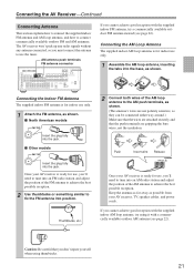
... AM loop antenna to use , you cannot achieve good reception with a commercially available outdoor AM antenna (see page 22). Once your AV receiver, TV, speaker cables, and power cords. Connecting the AM Loop Antenna The supplied indoor AM loop antenna is ready for indoor use only. 1 Assemble the... AM loop antenna, inserting the tabs into the base, as possible from your AV receiver is for use only. 1 Attach the FM antenna, as shown....
... AM loop antenna to use , you cannot achieve good reception with a commercially available outdoor AM antenna (see page 22). Once your AV receiver, TV, speaker cables, and power cords. Connecting the AM Loop Antenna The supplied indoor AM loop antenna is ready for indoor use only. 1 Assemble the... AM loop antenna, inserting the tabs into the base, as possible from your AV receiver is for use only. 1 Attach the FM antenna, as shown....

Owner Manual
Page 23
... Flow Video Audio Video Audio TV, projector, etc. When choosing a connection format, bear in mind that the AV receiver doesn't convert between them from the COMPONENT VIDEO OUT (see page 46). • For details on the HDMI jacks, see page 32. • ...supported by using any one for connection information) Which Connections Should I Use? Output IN AV receiver Optical Coaxial Analog Multichannel Optical Coaxial Analog Multichannel OUT Input MD recorder, etc. DVD player, etc. Speakers (see page 46). The format you choose will be set to upconvert composite video and S-...
... Flow Video Audio Video Audio TV, projector, etc. When choosing a connection format, bear in mind that the AV receiver doesn't convert between them from the COMPONENT VIDEO OUT (see page 46). • For details on the HDMI jacks, see page 32. • ...supported by using any one for connection information) Which Connections Should I Use? Output IN AV receiver Optical Coaxial Analog Multichannel Optical Coaxial Analog Multichannel OUT Input MD recorder, etc. DVD player, etc. Speakers (see page 46). The format you choose will be set to upconvert composite video and S-...
Owner Manual
Page 32
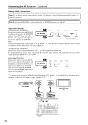
... video, S-Video, and component video jacks can be output through your TV speakers, set the HDMI Audio Out setting to On (see page 76) and your TV (see page 24). (TX-SR674/674E, TX-SR8467) Digital video signals received at HDMI IN 1 and 2 through the HDMI OUT (see page 45)....Video, or component video connection to your HDMI-compatible DVD player, TV, projector, and so on. IN AV receiver Composite Composite OUT S-Video S-Video Component HDMI * Component HDMI * TX-SR674/674E/8467 only Note: The onscreen setup menus are only output by the HDMI OUT. HDMI OUT HDMI IN DVD...
... video, S-Video, and component video jacks can be output through your TV speakers, set the HDMI Audio Out setting to On (see page 76) and your TV (see page 24). (TX-SR674/674E, TX-SR8467) Digital video signals received at HDMI IN 1 and 2 through the HDMI OUT (see page 45)....Video, or component video connection to your HDMI-compatible DVD player, TV, projector, and so on. IN AV receiver Composite Composite OUT S-Video S-Video Component HDMI * Component HDMI * TX-SR674/674E/8467 only Note: The onscreen setup menus are only output by the HDMI OUT. HDMI OUT HDMI IN DVD...
Owner Manual
Page 37
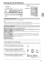
...that might interfere with other electrical equipment on page 38. Turning On and Standby 1 AV receiver Remote controller STANDBY/ON RECEIVER or ON/STANDBY Press the [STANDBY/ON] button. See "Automatic Speaker Setup (Audyssey2EQ)" on the same circuit. If you have , see "Changing the Input ...] button. The AV receiver will enter Standby mode. The AV receiver comes on the AV receiver, always turn it for the very first time. I Do the automatic speaker setup-this is essential! To prevent any loud surprises when you connected an Onkyo MD recorder, CD recorder...
...that might interfere with other electrical equipment on page 38. Turning On and Standby 1 AV receiver Remote controller STANDBY/ON RECEIVER or ON/STANDBY Press the [STANDBY/ON] button. See "Automatic Speaker Setup (Audyssey2EQ)" on the same circuit. If you have , see "Changing the Input ...] button. The AV receiver will enter Standby mode. The AV receiver comes on the AV receiver, always turn it for the very first time. I Do the automatic speaker setup-this is essential! To prevent any loud surprises when you connected an Onkyo MD recorder, CD recorder...
Owner Manual
Page 38
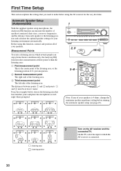
... the examples below, choose the listening area that you need to make before running the automatic speaker setup (see page 47). Measurement Points To create a listening area in which the AV receiver is connected. 38 The distances between points 1 and 2 and points 1 and 3 must ...be at three points within the listening area: A First measurement point This is 4 CINEFLTR ohms, change the minimum speaker impVeCRdanDVcDe seHDtDting before using this function, connect...
... the examples below, choose the listening area that you need to make before running the automatic speaker setup (see page 47). Measurement Points To create a listening area in which the AV receiver is connected. 38 The distances between points 1 and 2 and points 1 and 3 must ...be at three points within the listening area: A First measurement point This is 4 CINEFLTR ohms, change the minimum speaker impVeCRdanDVcDe seHDtDting before using this function, connect...
Owner Manual
Page 39
... headphones is picked up the room as the Audyssey2EQ function determines which speakers are : Next: Proceed to the SETUP MIC jack. Cancel: Cancel the automatic speaker setup. 39 Notes: • If the AV receiver was detected. zontal. • If there's an obstacle between the... microphone and any speaker, the automatic setup will provide better results. Set up by the...
... headphones is picked up the room as the Audyssey2EQ function determines which speakers are : Next: Proceed to the SETUP MIC jack. Cancel: Cancel the automatic speaker setup. 39 Notes: • If the AV receiver was detected. zontal. • If there's an obstacle between the... microphone and any speaker, the automatic setup will provide better results. Set up by the...

Owner Manual
Page 40
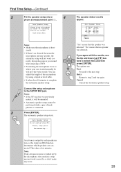
...Setup Mic. The following screen appears. plete, the following screen appears. This takes a few minutes. Audyssey2EQ performs more measurements. Auto Speaker Setup Save Review SP Config Review SP Distance Review SP Level Cancel Use the Up and Down [ ]/[ ] buttons to step 2... to select an option, and then press [ENTER]. Cancel: Cancel the automatic speaker setup. 9 Disconnect the speaker setup microphone. First Time Setup-Continued 5 6 7 40 The following screen appears. Auto Speaker Setup Please place microphone at left end of listening area at ear height. When...
...Setup Mic. The following screen appears. plete, the following screen appears. This takes a few minutes. Audyssey2EQ performs more measurements. Auto Speaker Setup Save Review SP Config Review SP Distance Review SP Level Cancel Use the Up and Down [ ]/[ ] buttons to step 2... to select an option, and then press [ENTER]. Cancel: Cancel the automatic speaker setup. 9 Disconnect the speaker setup microphone. First Time Setup-Continued 5 6 7 40 The following screen appears. Auto Speaker Setup Please place microphone at left end of listening area at ear height. When...
Owner Manual
Page 41
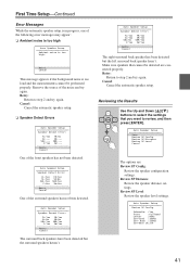
...to select the settings that cannot be performed properly. First Time Setup-Continued Error Messages While the automatic speaker setup is in progress, one of the surround speakers has not been detected. Auto Speaker Setup Speaker Detect Error: FL:Yes FR:Yes SL:Yes SR:No SBL:Yes SBR:Yes C:Yes SW:Yes...: FL:Yes FR:No SL:--- Retry Cancel This message appears if the background noise is too high. Review SP Level: Review the speaker level settings. Auto Speaker Setup Speaker Detect Error: FL:Yes FR:Yes SL:Yes SR:Yes SBL:No SBR:Yes C:Yes SW:Yes Retry Cancel The right surround back...
...to select the settings that cannot be performed properly. First Time Setup-Continued Error Messages While the automatic speaker setup is in progress, one of the surround speakers has not been detected. Auto Speaker Setup Speaker Detect Error: FL:Yes FR:Yes SL:Yes SR:No SBL:Yes SBR:Yes C:Yes SW:Yes...: FL:Yes FR:No SL:--- Retry Cancel This message appears if the background noise is too high. Review SP Level: Review the speaker level settings. Auto Speaker Setup Speaker Detect Error: FL:Yes FR:Yes SL:Yes SR:Yes SBL:No SBR:Yes C:Yes SW:Yes Retry Cancel The right surround back...

Owner Manual
Page 42
...is usually low, it to its highest crossover frequency, and then try running the speaker setup a second time still doesn't provide usable results, you 're using a... has a low-pass filter switch, set it may not be detected by the automatic speaker setup may not be detected, so use an appropriate volume level. If the subwoofer (SW) appears...Front :15ft Center :15ft SurrRight : 7ft SurrBack R : 7ft SurrBack L : 7ft SurrLeft : 7ft Subwoofer :15ft Auto Speaker Setup Review SP Level Left : Center : Right : SurrRight : SurrBack R : SurrBack L : SurrLeft : Subwoofer :...
...is usually low, it to its highest crossover frequency, and then try running the speaker setup a second time still doesn't provide usable results, you 're using a... has a low-pass filter switch, set it may not be detected by the automatic speaker setup may not be detected, so use an appropriate volume level. If the subwoofer (SW) appears...Front :15ft Center :15ft SurrRight : 7ft SurrBack R : 7ft SurrBack L : 7ft SurrLeft : 7ft Subwoofer :15ft Auto Speaker Setup Review SP Level Left : Center : Right : SurrRight : SurrBack R : SurrBack L : SurrLeft : Subwoofer :...
Owner Manual
Page 43
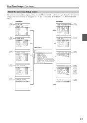
... connected TV and provide a convenient way to change the AV receiver's settings. (The onscreen menus do not appear on a TV that's connected to the HDMI OUT (TX-SR604/604E/8460 only).) Submenus Submenus p. 45 0.Video Input ...0dB c.Right : 0dB d.SurrRight : 0dB e.SurrBack R : 0dB f.SurrBack L : 0dB g.SurrLeft : 0dB h.Subwoofer : 0dB Menu 00.0VriadteioonInput 1.Speaker Config 2.Speaker Distance 3.Level Calibration 4.Equalizer Settings 5.Audio Adjust 6.Input Setup 7.Miscellaneous Setup 8.Hardware Setup 9.Lock Setup 7.Miscellaneous Setup a.MaximumVolume: Off b.PowerOnVolume: Last...
... connected TV and provide a convenient way to change the AV receiver's settings. (The onscreen menus do not appear on a TV that's connected to the HDMI OUT (TX-SR604/604E/8460 only).) Submenus Submenus p. 45 0.Video Input ...0dB c.Right : 0dB d.SurrRight : 0dB e.SurrBack R : 0dB f.SurrBack L : 0dB g.SurrLeft : 0dB h.Subwoofer : 0dB Menu 00.0VriadteioonInput 1.Speaker Config 2.Speaker Distance 3.Level Calibration 4.Equalizer Settings 5.Audio Adjust 6.Input Setup 7.Miscellaneous Setup 8.Hardware Setup 9.Lock Setup 7.Miscellaneous Setup a.MaximumVolume: Off b.PowerOnVolume: Last...

