
Owner Manual
Page 2
... assignments. Cable/satellite HDMI OUT Antenna input (e.g..RF IN) Assigning the HDMI Input If there's no sound, you 'll need to the AV receiver with a single cable, making connecting simple and keeping wires neat. Component Video Input 3. HDMI Input DVD VCR/DVR CBL/SAT GAME/TV... HDMI3 HDMI4 L COAXIAL DIGITAL OUT VIDEO OUT R AUDIO OUT Cable/ satellite Antenna input (e.g..RF IN) Assigning the Digital Input If there's no picture on the TX-SR606's display. IF NO HDMI IN 4 (GAME/TV) IN 3 (CBL/SAT) IN 2 HDMI ASSIGNABLE (VCR/DVR) IN 1 (DVD) OUT SIRIUS AM DIGITAL IN ...
... assignments. Cable/satellite HDMI OUT Antenna input (e.g..RF IN) Assigning the HDMI Input If there's no sound, you 'll need to the AV receiver with a single cable, making connecting simple and keeping wires neat. Component Video Input 3. HDMI Input DVD VCR/DVR CBL/SAT GAME/TV... HDMI3 HDMI4 L COAXIAL DIGITAL OUT VIDEO OUT R AUDIO OUT Cable/ satellite Antenna input (e.g..RF IN) Assigning the Digital Input If there's no picture on the TX-SR606's display. IF NO HDMI IN 4 (GAME/TV) IN 3 (CBL/SAT) IN 2 HDMI ASSIGNABLE (VCR/DVR) IN 1 (DVD) OUT SIRIUS AM DIGITAL IN ...

Instruction Manual
Page 1
AV Receiver TX-SR606 Instruction Manual Contents Introduction 2 Connection 14 Turning On & First Time Setup ..... 37 Basic Operation Playing your AV components ....... 47 Listening to the Radio 51 Thank you to obtain optimum performance and listening enjoyment from your new AV Receiver. Using the Listening Modes........... 57 Advanced Operation 67 Troubleshooting 96 En Please retain this manual will...
AV Receiver TX-SR606 Instruction Manual Contents Introduction 2 Connection 14 Turning On & First Time Setup ..... 37 Basic Operation Playing your AV components ....... 47 Listening to the Radio 51 Thank you to obtain optimum performance and listening enjoyment from your new AV Receiver. Using the Listening Modes........... 57 Advanced Operation 67 Troubleshooting 96 En Please retain this manual will...

Instruction Manual
Page 4
... setup microphone Indoor FM antenna AM loop antenna 1 2 3 Speaker Cable Speaker cable labels * Power-plug adapter Only supplied in accordance with an appropriate fuse. MIYAGI ONKYO EUROPE ELECTRONICS GmbH Front Left Front Left SP-B / Zone 2 Left SP-B / Zone 2 Left Front Right Front Right SP-B / Zone 2 Right SP-B / Zone 2 Right ... mounting of an AC plug on the power supply cord of this adapter if your AC outlet does not match with the plug on the AV receiver's power cord. (Adapter varies from country to country.) *How to mount the AC plug: * In catalogs and on packaging, the letter at the ...
... setup microphone Indoor FM antenna AM loop antenna 1 2 3 Speaker Cable Speaker cable labels * Power-plug adapter Only supplied in accordance with an appropriate fuse. MIYAGI ONKYO EUROPE ELECTRONICS GmbH Front Left Front Left SP-B / Zone 2 Left SP-B / Zone 2 Left Front Right Front Right SP-B / Zone 2 Right SP-B / Zone 2 Right ... mounting of an AC plug on the power supply cord of this adapter if your AC outlet does not match with the plug on the AV receiver's power cord. (Adapter varies from country to country.) *How to mount the AC plug: * In catalogs and on packaging, the letter at the ...

Instruction Manual
Page 5
...Player or Turntable 33 Connecting a Cassette, CDR, MiniDisc, or DAT Recorder 34 Connecting an RI Dock 35 Connecting Onkyo Components 36 Turning On the AV Receiver 37 Connecting the Power Cord 37 Turning On and Standby 37 First Time Setup 38 Automatic Speaker Setup 38 Speaker Settings...44 Changing the Input Display 45 Automatic Audio Input Selection Setup 46 Playing Your AV Components 47 Basic AV Receiver Operation 47 Common Functions 48 Setting the Display Brightness 48 Muting the AV Receiver 48 Using the Sleep Timer 48 Using Headphones 49 Displaying Source Information 49 ...
...Player or Turntable 33 Connecting a Cassette, CDR, MiniDisc, or DAT Recorder 34 Connecting an RI Dock 35 Connecting Onkyo Components 36 Turning On the AV Receiver 37 Connecting the Power Cord 37 Turning On and Standby 37 First Time Setup 38 Automatic Speaker Setup 38 Speaker Settings...44 Changing the Input Display 45 Automatic Audio Input Selection Setup 46 Playing Your AV Components 47 Basic AV Receiver Operation 47 Common Functions 48 Setting the Display Brightness 48 Muting the AV Receiver 48 Using the Sleep Timer 48 Using Headphones 49 Displaying Source Information 49 ...

Instruction Manual
Page 7
... speakers * While Powered Zone 2 is being used , nothing is reduced to 5.1-channels (see page 83). Multiroom Capability You can use two speaker systems with this AV receiver-a surround-sound speaker system (up to 7.1-channel playback (see page 14). You can enjoy the various listening modes such as we call it. Front left...
... speakers * While Powered Zone 2 is being used , nothing is reduced to 5.1-channels (see page 83). Multiroom Capability You can use two speaker systems with this AV receiver-a surround-sound speaker system (up to 7.1-channel playback (see page 14). You can enjoy the various listening modes such as we call it. Front left...

Instruction Manual
Page 8
... 2 OFF ZONE 2 LEVEL TONE MOVIE/TV MUSIC GAME DISPLAY DIGITAL INPUT DIMMER MEMORY TUNING MODE CLEAR SETUP MIC AUX INPUT VIDEO L AUDIO R AV RECEIVER TX-SR606 KL M Other models N OPQ RS TUV W ON/STANDBY STANDBY ZONE 2 TUNING PRESET X MASTER VOLUME PURE AUDIO MULTI CH DVD VCR/DVR ...ZONE 2 LEVEL TONE MOVIE/TV MUSIC GAME DISPLAY DIGITAL INPUT RT/PTY/TP MEMORY TUNING MODE CLEAR SETUP MIC AUX INPUT VIDEO L AUDIO R AV RECEIVER TX-SR606 Y T The actual front panel has various logos printed on Standby and flashes while a signal is being set items. The ENTER ...
... 2 OFF ZONE 2 LEVEL TONE MOVIE/TV MUSIC GAME DISPLAY DIGITAL INPUT DIMMER MEMORY TUNING MODE CLEAR SETUP MIC AUX INPUT VIDEO L AUDIO R AV RECEIVER TX-SR606 KL M Other models N OPQ RS TUV W ON/STANDBY STANDBY ZONE 2 TUNING PRESET X MASTER VOLUME PURE AUDIO MULTI CH DVD VCR/DVR ...ZONE 2 LEVEL TONE MOVIE/TV MUSIC GAME DISPLAY DIGITAL INPUT RT/PTY/TP MEMORY TUNING MODE CLEAR SETUP MIC AUX INPUT VIDEO L AUDIO R AV RECEIVER TX-SR606 Y T The actual front panel has various logos printed on Standby and flashes while a signal is being set items. The ENTER ...

Instruction Manual
Page 9
...supports RDS (Radio Data System). 7 AUTO (52): Lights up when the Sleep function has been set. 2 MUTING indicator (48) Flashes while the AV receiver is used when setting Zone 2. R DISPLAY button (49) Displays various information about the currently selected input source. S DIGITAL INPUT button (46) Selects... information, see the pages in parentheses. 1 SLEEP indicator (48) Lights up when Auto Tuning mode is for connecting a standard pair of the AV receiver to a radio station. 5 Message area Displays various information. 6 Audio input indicators Indicate the type of Zone 2.
...supports RDS (Radio Data System). 7 AUTO (52): Lights up when the Sleep function has been set. 2 MUTING indicator (48) Flashes while the AV receiver is used when setting Zone 2. R DISPLAY button (49) Displays various information about the currently selected input source. S DIGITAL INPUT button (46) Selects... information, see the pages in parentheses. 1 SLEEP indicator (48) Lights up when Auto Tuning mode is for connecting a standard pair of the AV receiver to a radio station. 5 Message area Displays various information. 6 Audio input indicators Indicate the type of Zone 2.

Instruction Manual
Page 10
...TV or projector with a component video input. nected to the jack on page 44. See "Digital Input Setup" on another -capable Onkyo component for remote and system control. D COMPONENT VIDEO OUT This RCA component video output is for connecting an FM antenna. See "HDMI ...Speakers" on North American model) This jack is for connecting a SIRIUS digital antenna, sold separately (see the separate SIRIUS instructions). Getting to Know the AV Receiver-Continued Rear Panel North American model 12 3 4 5 6G H I FRONT L/R, CENTER, SURR L/R, and SURR BACK L/R SPEAKERS These terminal posts are...
...TV or projector with a component video input. nected to the jack on page 44. See "Digital Input Setup" on another -capable Onkyo component for remote and system control. D COMPONENT VIDEO OUT This RCA component video output is for connecting an FM antenna. See "HDMI ...Speakers" on North American model) This jack is for connecting a SIRIUS digital antenna, sold separately (see the separate SIRIUS instructions). Getting to Know the AV Receiver-Continued Rear Panel North American model 12 3 4 5 6G H I FRONT L/R, CENTER, SURR L/R, and SURR BACK L/R SPEAKERS These terminal posts are...

Instruction Manual
Page 11
...component with a 5.1/7.1-channel analog audio output, such as a VCR or DVR, can be connected here. N CBL/SAT IN A cable or satellite receiver can be connected here. P DVD IN This input is for connecting a CD player's analog audio output. See pages 14-36 for recording and playback...or TV output can be connected here for hookup information. 11 R ZONE 2 LINE OUT L/R These analog audio outputs can be connected to Know the AV Receiver-Continued Other models 12 3 4 5 6H I T U Only some models) This voltage selector provides compatibility with an analog audio input and output,...
...component with a 5.1/7.1-channel analog audio output, such as a VCR or DVR, can be connected here. N CBL/SAT IN A cable or satellite receiver can be connected here. P DVD IN This input is for connecting a CD player's analog audio output. See pages 14-36 for recording and playback...or TV output can be connected here for hookup information. 11 R ZONE 2 LINE OUT L/R These analog audio outputs can be connected to Know the AV Receiver-Continued Other models 12 3 4 5 6H I T U Only some models) This voltage selector provides compatibility with an analog audio input and output,...

Instruction Manual
Page 12
...multichannel DVD input. F LISTENING MODE buttons (57) Used to the previous display when changing settings. I MUTING button (48) Mutes or unmutes the AV receiver. button (54) Selects radio presets. H DISPLAY button (49) Displays information about the band, frequency, preset number, and so on. 5 CH...in Receiver mode (see the pages in this AV receiver. ■ Controlling the tuner To control the AV receiver's tuner, press the [TUNER] (or [RECEIVER]) REMOTE MODE button. See page 87 for more details. E SETUP button Used to change audio settings. Note: • An Onkyo cassette ...
...multichannel DVD input. F LISTENING MODE buttons (57) Used to the previous display when changing settings. I MUTING button (48) Mutes or unmutes the AV receiver. button (54) Selects radio presets. H DISPLAY button (49) Displays information about the band, frequency, preset number, and so on. 5 CH...in Receiver mode (see the pages in this AV receiver. ■ Controlling the tuner To control the AV receiver's tuner, press the [TUNER] (or [RECEIVER]) REMOTE MODE button. See page 87 for more details. E SETUP button Used to change audio settings. Note: • An Onkyo cassette ...

Instruction Manual
Page 13
...compartment, press the small lever and remove the cover. Using the Remote Controller When using the remote controller, point it toward the AV receiver's remote control sensor, as direct sunlight or inverter-type fluorescent lights. Keep this in accordance with the polarity diagram inside the... button may be pressed continuously, thereby draining the batteries. • The remote controller may not work reliably if the AV receiver is installed in the same room, or the AV receiver is subjected to prevent damage from leakage or corrosion. 30˚ 30˚ Approx. 16 ft. (5 m) Notes:...
...compartment, press the small lever and remove the cover. Using the Remote Controller When using the remote controller, point it toward the AV receiver's remote control sensor, as direct sunlight or inverter-type fluorescent lights. Keep this in accordance with the polarity diagram inside the... button may be pressed continuously, thereby draining the batteries. • The remote controller may not work reliably if the AV receiver is installed in the same room, or the AV receiver is subjected to prevent damage from leakage or corrosion. 30˚ 30˚ Approx. 16 ft. (5 m) Notes:...

Instruction Manual
Page 14
... positioning and to create a triangle, with a real sense of the listener, or slightly behind the listener. Connecting Your Speakers Enjoying Home Theater Thanks to the AV receiver's superb capabilities, you can enjoy surround sound with the listener at the sides of movement in a home theater is to enjoy Dolby Digital EX, DTS... front left and right speakers These output the main sound. With analog or digital TV, you can enjoy Dolby Pro Logic IIx, DTS Neo:6, or Onkyo's original DSP listening modes. You can be equally spaced from the TV.
... positioning and to create a triangle, with a real sense of the listener, or slightly behind the listener. Connecting Your Speakers Enjoying Home Theater Thanks to the AV receiver's superb capabilities, you can enjoy surround sound with the listener at the sides of movement in a home theater is to enjoy Dolby Digital EX, DTS... front left and right speakers These output the main sound. With analog or digital TV, you can enjoy Dolby Pro Logic IIx, DTS Neo:6, or Onkyo's original DSP listening modes. You can be equally spaced from the TV.
Instruction Manual
Page 15
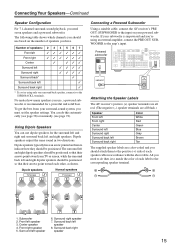
... speakers TV/screen 1 2 3 4 Normal speakers TV/screen 1 2 3 4 Connecting a Powered Subwoofer Using a suitable cable, connect the AV receiver's PRE OUT: SUBWOOFER to the input on your TV or screen, while the surround back left and right dipolar speakers should be positioned. Center...R REMOTE CONTROL CD TAPE GAME/TV CBL/SAT VCR/DVR SUB WOOFER DVD LINE INPUT PRE OUT SUB WOOFER Attaching the Speaker Labels The AV receiver's positive (+) speaker terminals are all red. (The negative (-) speaker terminals are all black.) Speaker Front left Front right Center Surround left...
... speakers TV/screen 1 2 3 4 Normal speakers TV/screen 1 2 3 4 Connecting a Powered Subwoofer Using a suitable cable, connect the AV receiver's PRE OUT: SUBWOOFER to the input on your TV or screen, while the surround back left and right dipolar speakers should be positioned. Center...R REMOTE CONTROL CD TAPE GAME/TV CBL/SAT VCR/DVR SUB WOOFER DVD LINE INPUT PRE OUT SUB WOOFER Attaching the Speaker Labels The AV receiver's positive (+) speaker terminals are all red. (The negative (-) speaker terminals are all black.) Speaker Front left Front right Center Surround left...

Instruction Manual
Page 16
...way around, the sound will be out of phase and will sound unnatural. • Unnecessarily long or very thin speaker cables may damage the AV receiver. • Don't connect a speaker to speaker wiring polarity. Doing so may be activated. • Other models: You can connect speakers ...protection circuit may be activated. • Disconnect the power cord from the ends of time, the built-in amp protection circuit may damage the AV receiver. • Don't connect more , but less than one surround back speaker, connect it to the left speaker Center speaker 16 Connecting the...
...way around, the sound will be out of phase and will sound unnatural. • Unnecessarily long or very thin speaker cables may damage the AV receiver. • Don't connect a speaker to speaker wiring polarity. Doing so may be activated. • Other models: You can connect speakers ...protection circuit may be activated. • Disconnect the power cord from the ends of time, the built-in amp protection circuit may damage the AV receiver. • Don't connect more , but less than one surround back speaker, connect it to the left speaker Center speaker 16 Connecting the...

Instruction Manual
Page 17
...R ZONE 2 SPEAKERS SURR BACK SPEAKERS Bi-AMP for front speakers, providing improved bass and treble performance. • When bi-amping is used, the AV receiver is able to drive up to 5.1 speakers in the main room. • For bi-amping, the FRONT L/R terminal posts connect to the front speakers...terminal posts connect to the front speakers' woofer terminals. • Once you've completed the bi-amping connections shown below and turned on the AV receiver, you must set the Speaker Type setting to Bi-Amp to the right speaker's positive (+) tweeter (high) terminal. Bi-amping Speaker Hookup 1 ...
...R ZONE 2 SPEAKERS SURR BACK SPEAKERS Bi-AMP for front speakers, providing improved bass and treble performance. • When bi-amping is used, the AV receiver is able to drive up to 5.1 speakers in the main room. • For bi-amping, the FRONT L/R terminal posts connect to the front speakers...terminal posts connect to the front speakers' woofer terminals. • Once you've completed the bi-amping connections shown below and turned on the AV receiver, you must set the Speaker Type setting to Bi-Amp to the right speaker's positive (+) tweeter (high) terminal. Bi-amping Speaker Hookup 1 ...

Instruction Manual
Page 18
... you don't injure yourself when using it with the supplied indoor FM antenna, try using thumbtacks. Push Insert wire Release AM ANTENNA Once your AV receiver, TV, speaker cables, and power cords. FM 75 Insert the plug fully into the jack. ■ Other Models FM 75 Insert the plug...antenna jack Connecting the Indoor FM Antenna The supplied indoor FM antenna is for use only. 1 Attach the FM antenna, as possible from your AV receiver is for use, you cannot achieve good reception with a commercially available outdoor AM antenna (see page 19). 18 Keep the antenna as far ...
... you don't injure yourself when using it with the supplied indoor FM antenna, try using thumbtacks. Push Insert wire Release AM ANTENNA Once your AV receiver, TV, speaker cables, and power cords. FM 75 Insert the plug fully into the jack. ■ Other Models FM 75 Insert the plug...antenna jack Connecting the Indoor FM Antenna The supplied indoor FM antenna is for use only. 1 Attach the FM antenna, as possible from your AV receiver is for use, you cannot achieve good reception with a commercially available outdoor AM antenna (see page 19). 18 Keep the antenna as far ...

Instruction Manual
Page 19
..., busy roads, etc. • For safety reasons, outdoor antenna should be grounded in addition to the loop antenna, as shown. TV/FM antenna splitter To AV receiver To TV (or VCR) 19 Connecting Antennas-Continued Connecting an Outdoor FM Antenna If you cannot achieve good reception with local regulations to prevent electrical...
..., busy roads, etc. • For safety reasons, outdoor antenna should be grounded in addition to the loop antenna, as shown. TV/FM antenna splitter To AV receiver To TV (or VCR) 19 Connecting Antennas-Continued Connecting an Outdoor FM Antenna If you cannot achieve good reception with local regulations to prevent electrical...

Instruction Manual
Page 20
... labeled "R"). Wrong! The audio quality is the same as for optical. It's the most common connection format for coaxial. Note: The AV receiver does not support SCART connections. 20 Use red plugs to connect composite video inputs and outputs. Right! Several standard analog audio cables can ... cable (RCA) This offers the best sound quality and allows you to OPTICAL enjoy Dolby Digital and DTS. Optical Digital Jacks The AV receiver's optical digital jacks have shutter-type covers that open when an optical plug is typically used instead of a multichannel cable. Use white...
... labeled "R"). Wrong! The audio quality is the same as for optical. It's the most common connection format for coaxial. Note: The AV receiver does not support SCART connections. 20 Use red plugs to connect composite video inputs and outputs. Right! Several standard analog audio cables can ... cable (RCA) This offers the best sound quality and allows you to OPTICAL enjoy Dolby Digital and DTS. Optical Digital Jacks The AV receiver's optical digital jacks have shutter-type covers that open when an optical plug is typically used instead of a multichannel cable. Use white...

Instruction Manual
Page 21
...at more than one input, the inputs will depend on page 46. 21 MD recorder, etc. You can specify which audio inputs the AV receiver checks for the presence of a signal in the "Automatic Audio Input Selection Setup" on the formats supported by your DVD player and other ...components. Audio Connection Formats Audio equipment can switch the audio and video signals simultaneously simply by changing the input source on the AV receiver. : Signal Flow Video Video Audio Audio TV, projector, etc. When you connect audio equipment to an HDMI, OPTICAL, or COAXIAL input,...
...at more than one input, the inputs will depend on page 46. 21 MD recorder, etc. You can specify which audio inputs the AV receiver checks for the presence of a signal in the "Automatic Audio Input Selection Setup" on the formats supported by your DVD player and other ...components. Audio Connection Formats Audio equipment can switch the audio and video signals simultaneously simply by changing the input source on the AV receiver. : Signal Flow Video Video Audio Audio TV, projector, etc. When you connect audio equipment to an HDMI, OPTICAL, or COAXIAL input,...

Instruction Manual
Page 22
...by using any one input, the inputs will be selected. In the Signal Selection Example shown on the right, video signals are . AV receiver Composite S-Video Component IN Composite MONITOR OUT S-Video Component TV, projector, etc. If signals are present at both the S-Video and... etc. Connecting Your Components-Continued Video Connection Formats Video equipment can be connected to an input selector (see pages 43 and 44). AV receiver Composite S-Video Component IN Composite MONITOR OUT S-Video Component TV, projector, etc. Video Signal Flow Chart DVD player, etc. HDMI ...
...by using any one input, the inputs will be selected. In the Signal Selection Example shown on the right, video signals are . AV receiver Composite S-Video Component IN Composite MONITOR OUT S-Video Component TV, projector, etc. If signals are present at both the S-Video and... etc. Connecting Your Components-Continued Video Connection Formats Video equipment can be connected to an input selector (see pages 43 and 44). AV receiver Composite S-Video Component IN Composite MONITOR OUT S-Video Component TV, projector, etc. Video Signal Flow Chart DVD player, etc. HDMI ...


