
Owner Manual
Page 2
...connect your DVD player to the AV receiver's HDMI1, and connect your TV, you'll need to the HDMI OUT. Speaker Setup 3. Hardware Setup 8. Lock Setup 1. AV Component Hookup See the other side of this sheet for the Speaker hookup. Digital audio signals received at HDMI IN inputs are not... using Cable/satellite box, please refer to assign the HDMI inputs as shown above, it 's not necessary to the AV receiver's COAXIAL 1 DIGITAL IN, and your TV or player doesn't support HDMI, use the TX-SR606's display when changing ...
...connect your DVD player to the AV receiver's HDMI1, and connect your TV, you'll need to the HDMI OUT. Speaker Setup 3. Hardware Setup 8. Lock Setup 1. AV Component Hookup See the other side of this sheet for the Speaker hookup. Digital audio signals received at HDMI IN inputs are not... using Cable/satellite box, please refer to assign the HDMI inputs as shown above, it 's not necessary to the AV receiver's COAXIAL 1 DIGITAL IN, and your TV or player doesn't support HDMI, use the TX-SR606's display when changing ...

Instruction Manual
Page 5
... Antenna 18 Connecting an Outdoor FM Antenna 19 Connecting an Outdoor AM Antenna 19 Connecting Your Components 20 About AV Connections 20 Connecting Audio and Video Signals to the AV Receiver 21 Which Connections Should I Use 21 Connecting a TV or Projector 23 Connecting a DVD player 24 Connecting ...Player or Turntable 33 Connecting a Cassette, CDR, MiniDisc, or DAT Recorder 34 Connecting an RI Dock 35 Connecting Onkyo Components 36 Turning On the AV Receiver 37 Connecting the Power Cord 37 Turning On and Standby 37 First Time Setup 38 Automatic Speaker Setup 38 Speaker ...
... Antenna 18 Connecting an Outdoor FM Antenna 19 Connecting an Outdoor AM Antenna 19 Connecting Your Components 20 About AV Connections 20 Connecting Audio and Video Signals to the AV Receiver 21 Which Connections Should I Use 21 Connecting a TV or Projector 23 Connecting a DVD player 24 Connecting ...Player or Turntable 33 Connecting a Cassette, CDR, MiniDisc, or DAT Recorder 34 Connecting an RI Dock 35 Connecting Onkyo Components 36 Turning On the AV Receiver 37 Connecting the Power Cord 37 Turning On and Standby 37 First Time Setup 38 Automatic Speaker Setup 38 Speaker ...

Instruction Manual
Page 8
... OFF ZONE 2 LEVEL TONE MOVIE/TV MUSIC GAME DISPLAY DIGITAL INPUT DIMMER MEMORY TUNING MODE CLEAR SETUP MIC AUX INPUT VIDEO L AUDIO R AV RECEIVER TX-SR606 KL M Other models N OPQ RS TUV W ON/STANDBY STANDBY ZONE 2 TUNING PRESET X MASTER VOLUME PURE AUDIO MULTI CH DVD VCR/... 9. They are not shown here for each item. The [MULTI CH] button selects the multichannel DVD input. 8 E Remote-control sensor (13) Receives control signals from the remote controller. C ZONE 2 indicator (85) Flashes when Zone 2 is on . D Input selector buttons (47) Select the following input...
... OFF ZONE 2 LEVEL TONE MOVIE/TV MUSIC GAME DISPLAY DIGITAL INPUT DIMMER MEMORY TUNING MODE CLEAR SETUP MIC AUX INPUT VIDEO L AUDIO R AV RECEIVER TX-SR606 KL M Other models N OPQ RS TUV W ON/STANDBY STANDBY ZONE 2 TUNING PRESET X MASTER VOLUME PURE AUDIO MULTI CH DVD VCR/... 9. They are not shown here for each item. The [MULTI CH] button selects the multichannel DVD input. 8 E Remote-control sensor (13) Receives control signals from the remote controller. C ZONE 2 indicator (85) Flashes when Zone 2 is on . D Input selector buttons (47) Select the following input...

Instruction Manual
Page 9
... up when the Sleep function has been set. 2 MUTING indicator (48) Flashes while the AV receiver is muted. 3 Listening mode and format indicators (57) Show the selected listening mode and audio input signal format. 4 Tuning indicators (52) FM STEREO (52): Lights up when Auto Tuning mode ...headphones for use with RDS (Radio Data System). M ZONE 2 LEVEL button (86) Used when adjusting the volume level of the AV receiver to Know the AV Receiver-Continued For detailed information, see the pages in parentheses. U MEMORY button (54) Used when storing or deleting radio presets. There...
... up when the Sleep function has been set. 2 MUTING indicator (48) Flashes while the AV receiver is muted. 3 Listening mode and format indicators (57) Show the selected listening mode and audio input signal format. 4 Tuning indicators (52) FM STEREO (52): Lights up when Auto Tuning mode ...headphones for use with RDS (Radio Data System). M ZONE 2 LEVEL button (86) Used when adjusting the volume level of the AV receiver to Know the AV Receiver-Continued For detailed information, see the pages in parentheses. U MEMORY button (54) Used when storing or deleting radio presets. There...

Instruction Manual
Page 11
... S-Video and composite video input and output jacks for connecting the video signal, and there are S-Video and composite video input jacks for recording and playback. S SUBWOOFER PRE OUT This analog audio output can be connected to Know the AV Receiver-Continued Other models 12 3 4 5 6H I T U Only some models) This voltage selector provides...
... S-Video and composite video input and output jacks for connecting the video signal, and there are S-Video and composite video input jacks for recording and playback. S SUBWOOFER PRE OUT This analog audio output can be connected to Know the AV Receiver-Continued Other models 12 3 4 5 6H I T U Only some models) This voltage selector provides...

Instruction Manual
Page 18
... into an FM radio station and adjust the position of the AM loop antenna to fix the FM antenna into the jack. Once your AV receiver, TV, speaker cables, and power cords. Connecting Antennas This section explains how to connect the supplied indoor FM antenna and AM loop antenna,... FM 75 Insert the plug fully into the jack. ■ Other Models FM 75 Insert the plug fully into position. The AV receiver won't pick up any radio signals without any antenna connected, so you don't injure yourself when using it with the supplied indoor FM antenna, try using thumbtacks. ...
... into an FM radio station and adjust the position of the AM loop antenna to fix the FM antenna into the jack. Once your AV receiver, TV, speaker cables, and power cords. Connecting Antennas This section explains how to connect the supplied indoor FM antenna and AM loop antenna,... FM 75 Insert the plug fully into the jack. ■ Other Models FM 75 Insert the plug fully into position. The AV receiver won't pick up any radio signals without any antenna connected, so you don't injure yourself when using it with the supplied indoor FM antenna, try using thumbtacks. ...

Instruction Manual
Page 20
...and color signals and provides better picture quality than composite video. Note: The AV receiver does not support SCART connections. 20 AV Connection Color Coding RCA-type AV connections are usually color coded: red, white, and yellow. AV Cables and Jacks • Push plugs in all AV connections. ... best sound quality and allows you 've completed and double-checked all the way. Push plugs in all AV components. Optical Digital Jacks The AV receiver's optical digital jacks have shutter-type covers that open when an optical plug is commonly used instead of ...
...and color signals and provides better picture quality than composite video. Note: The AV receiver does not support SCART connections. 20 AV Connection Color Coding RCA-type AV connections are usually color coded: red, white, and yellow. AV Cables and Jacks • Push plugs in all AV connections. ... best sound quality and allows you 've completed and double-checked all the way. Push plugs in all AV components. Optical Digital Jacks The AV receiver's optical digital jacks have shutter-type covers that open when an optical plug is commonly used instead of ...

Instruction Manual
Page 21
...DVD player and other components. Connecting Your Components-Continued Connecting Audio and Video Signals to the AV Receiver By connecting both the audio and video outputs of your other AV components to the AV receiver, you choose will be connected to an HDMI, OPTICAL, or COAXIAL input..., you must assign that the AV receiver does not convert digital input signals for the presence of a signal in the following sections as a guide. Audio Connection Formats Audio equipment can specify which audio inputs the AV receiver checks for analog line outputs and vice versa....
...DVD player and other components. Connecting Your Components-Continued Connecting Audio and Video Signals to the AV Receiver By connecting both the audio and video outputs of your other AV components to the AV receiver, you choose will be connected to an HDMI, OPTICAL, or COAXIAL input..., you must assign that the AV receiver does not convert digital input signals for the presence of a signal in the following sections as a guide. Audio Connection Formats Audio equipment can specify which audio inputs the AV receiver checks for analog line outputs and vice versa....

Instruction Manual
Page 22
... offering the best picture quality. HDMI HDMI HDMI HDMI 22 AV receiver Composite S-Video Component IN Composite MONITOR OUT S-Video Component TV, projector, etc. Video input signals flow through their respective input signals as shown, with composite video, SVideo, and component video sources... input selector, that input to an input selector (see pages 43 and 44). AV receiver Composite S-Video Component IN Composite MONITOR OUT S-Video Component TV, projector, etc. If signals are present at more than one of priority: HDMI, component video, S-Video, composite...
... offering the best picture quality. HDMI HDMI HDMI HDMI 22 AV receiver Composite S-Video Component IN Composite MONITOR OUT S-Video Component TV, projector, etc. Video input signals flow through their respective input signals as shown, with composite video, SVideo, and component video sources... input selector, that input to an input selector (see pages 43 and 44). AV receiver Composite S-Video Component IN Composite MONITOR OUT S-Video Component TV, projector, etc. If signals are present at more than one of priority: HDMI, component video, S-Video, composite...

Instruction Manual
Page 23
If your TV has no audio outputs, connect an audio output from your VCR or cable or satellite receiver to the AV receiver and use its tuner to listen to and record audio from your TV or listen in Zone 2. • To enjoy Dolby Digital and ... connection b or c . (To record or listen in Zone 2 as well, use a and b , or a and c .) Connection A B C a b c AV receiver COMPONENT VIDEO OUT MONITOR OUT S MONITOR OUT V GAME/TV IN L/R DIGITAL IN COAXIAL 2 DIGITAL IN OPTICAL 1 Signal flow TV Component video input S-Video input Composite video input Analog audio L/R output Digital coaxial output...
If your TV has no audio outputs, connect an audio output from your VCR or cable or satellite receiver to the AV receiver and use its tuner to listen to and record audio from your TV or listen in Zone 2. • To enjoy Dolby Digital and ... connection b or c . (To record or listen in Zone 2 as well, use a and b , or a and c .) Connection A B C a b c AV receiver COMPONENT VIDEO OUT MONITOR OUT S MONITOR OUT V GAME/TV IN L/R DIGITAL IN COAXIAL 2 DIGITAL IN OPTICAL 1 Signal flow TV Component video input S-Video input Composite video input Analog audio L/R output Digital coaxial output...

Instruction Manual
Page 24
... use a and b , or a and c .) • If your DVD player ( A , B , or C ), and then make the connection. Connection A B C a b c AV receiver COMPONENT VIDEO IN 1 DVD IN S DVD IN V DVD IN FRONT L/R DIGITAL IN COAXIAL 1 DIGITAL IN OPTICAL 1 Signal flow DVD player Component video output S-Video output Composite video output Analog audio L/R output Digital coaxial output...
... use a and b , or a and c .) • If your DVD player ( A , B , or C ), and then make the connection. Connection A B C a b c AV receiver COMPONENT VIDEO IN 1 DVD IN S DVD IN V DVD IN FRONT L/R DIGITAL IN COAXIAL 1 DIGITAL IN OPTICAL 1 Signal flow DVD player Component video output S-Video output Composite video output Analog audio L/R output Digital coaxial output...

Instruction Manual
Page 26
...GAME/TV CBL/SAT VCR/DVR a SUB WOOFER DVD COAXIAL OUT OPTICAL OUT Connect one or the other Connection b must connect the AV receiver to your favorite TV programs via the AV receiver, which is useful if your VCR or DVR ( A , B , or C ), and then make the connection. •... Dolby Digital and DTS, use a and b , or a and c .) Connection A B C a b c b c AV receiver COMPONENT VIDEO IN 2 VCR/DVR IN S VCR/DVR IN V VCR/DVR IN L/R DIGITAL IN COAXIAL 2 DIGITAL IN OPTICAL 1 Signal flow VCR or DVR Component video output S-Video output Composite video output Analog audio L/R output...
...GAME/TV CBL/SAT VCR/DVR a SUB WOOFER DVD COAXIAL OUT OPTICAL OUT Connect one or the other Connection b must connect the AV receiver to your favorite TV programs via the AV receiver, which is useful if your VCR or DVR ( A , B , or C ), and then make the connection. •... Dolby Digital and DTS, use a and b , or a and c .) Connection A B C a b c b c AV receiver COMPONENT VIDEO IN 2 VCR/DVR IN S VCR/DVR IN V VCR/DVR IN L/R DIGITAL IN COAXIAL 2 DIGITAL IN OPTICAL 1 Signal flow VCR or DVR Component video output S-Video output Composite video output Analog audio L/R output...
Instruction Manual
Page 27
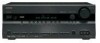
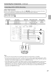
... S-Video inputs can only be recorded via the VCR/DVR OUT V jack. Likewise, video signals connected to the recording VCR/DVR's audio and video inputs. Connection A B a AV receiver VCR/DVR OUT S VCR/DVR OUT V VCR/DVR OUT L/R Signal flow ⇒ ⇒ ⇒ VCR or DVD recorder S-Video input Composite video... be turned on Standby. • If you want to record directly from your TV or another video source without going through the AV receiver, connect the audio and video outputs from your TV or VCR/DVR for details. • Video signals connected to the VCR/DVR OUT S jack. 27
... S-Video inputs can only be recorded via the VCR/DVR OUT V jack. Likewise, video signals connected to the recording VCR/DVR's audio and video inputs. Connection A B a AV receiver VCR/DVR OUT S VCR/DVR OUT V VCR/DVR OUT L/R Signal flow ⇒ ⇒ ⇒ VCR or DVD recorder S-Video input Composite video... be turned on Standby. • If you want to record directly from your TV or another video source without going through the AV receiver, connect the audio and video outputs from your TV or VCR/DVR for details. • Video signals connected to the VCR/DVR OUT S jack. 27

Instruction Manual
Page 28
.... With this hookup, you can use a and b , or a and c .) Connection A B C a b c AV receiver COMPONENT VIDEO IN 2 CBL/SAT IN S CBL/SAT IN V CBL/SAT IN L/R DIGITAL IN COAXIAL 2 DIGITAL IN OPTICAL 1 Signal flow Video source Component video output S-Video output Composite video output Analog audio L/R output Digital...SUB WOOFER a DVD COAXIAL OUT OPTICAL OUT Connect one or the other Connection c must connect the AV receiver to your favorite TV programs via the AV receiver, which is useful if your TV with the same type of connection. Connecting Your Components-Continued ...
.... With this hookup, you can use a and b , or a and c .) Connection A B C a b c AV receiver COMPONENT VIDEO IN 2 CBL/SAT IN S CBL/SAT IN V CBL/SAT IN L/R DIGITAL IN COAXIAL 2 DIGITAL IN OPTICAL 1 Signal flow Video source Component video output S-Video output Composite video output Analog audio L/R output Digital...SUB WOOFER a DVD COAXIAL OUT OPTICAL OUT Connect one or the other Connection c must connect the AV receiver to your favorite TV programs via the AV receiver, which is useful if your TV with the same type of connection. Connecting Your Components-Continued ...

Instruction Manual
Page 29
... that matches your game console ( A , B , or C ), and then make the connection. • With connection a , you must connect the AV receiver to and record audio from your game console or listen in Zone 2. • To enjoy Dolby Digital and DTS, use connection b . (To record or... listen in Zone 2 as well, use a and b .) Connection A B C a b AV receiver COMPONENT VIDEO IN 2 GAME/TV IN S GAME/TV IN V GAME/TV IN L/R DIGITAL OPTICAL IN 1 Signal flow Game console Component video output S-Video output Composite video output Analog audio L/R output Digital coaxial output...
... that matches your game console ( A , B , or C ), and then make the connection. • With connection a , you must connect the AV receiver to and record audio from your game console or listen in Zone 2. • To enjoy Dolby Digital and DTS, use connection b . (To record or... listen in Zone 2 as well, use a and b .) Connection A B C a b AV receiver COMPONENT VIDEO IN 2 GAME/TV IN S GAME/TV IN V GAME/TV IN L/R DIGITAL OPTICAL IN 1 Signal flow Game console Component video output S-Video output Composite video output Analog audio L/R output Digital coaxial output...

Instruction Manual
Page 30
...standard set -top boxes, and other video components. The AV receiver's HDMI interface is compatible with DVI (Digital Visual Interface),*1 so TVs and displays with a DVI input can carry control signals, digital video, and up to the AV receiver via HDMI must be connected by Intel for connecting TVs..., projectors, DVD players, set by the DDWG*3 in no picture.) The AV receiver uses HDCP (High-bandwidth Digital Content Protection), so ...
...standard set -top boxes, and other video components. The AV receiver's HDMI interface is compatible with DVI (Digital Visual Interface),*1 so TVs and displays with a DVI input can carry control signals, digital video, and up to the AV receiver via HDMI must be connected by Intel for connecting TVs..., projectors, DVD players, set by the DDWG*3 in no picture.) The AV receiver uses HDCP (High-bandwidth Digital Content Protection), so ...

Instruction Manual
Page 31
...-DVI adapter cable. (Note that its setup. Refer to the AV receiver. Hint! Normally, they are not output by the speakers and headphones connected to the connected component's instruction manual for details. 31 In addition, video signals from a component connected via HDMI, check its video can be ...page 43). ■ Video Signals Digital video signals received by the HDMI IN jacks are not supported. • When listening to an HDMI component through your TV's speakers, set the Audio TV Out setting to an input selector in no sound from the AV receiver or the sound may result...
...-DVI adapter cable. (Note that its setup. Refer to the AV receiver. Hint! Normally, they are not output by the speakers and headphones connected to the connected component's instruction manual for details. 31 In addition, video signals from a component connected via HDMI, check its video can be ...page 43). ■ Video Signals Digital video signals received by the HDMI IN jacks are not supported. • When listening to an HDMI component through your TV's speakers, set the Audio TV Out setting to an input selector in no sound from the AV receiver or the sound may result...

Instruction Manual
Page 32
Connecting Your Components-Continued Connecting a Camcorder or Other Device Step 1: Make the video connection A . TUNING PRESET MASTER VOLUME a AUX INPUT L AUDIO R SETUP ENTER RETURN TUNING MODE SETUP MIC AUX INPUT VIDEO L AUDIO R AV RECEIVER TX-SR606 A AUX INPUT VIDEO L AUDIO R OUT VIDEO OUT Camcorder, etc. Step 2: Make the audio connection a . Connection A a AV receiver AUX INPUT VIDEO AUX INPUT L-AUDIO-R Signal flow ⇐ ⇐ Camcorder or console Composite video output Analog audio L/R output 32
Connecting Your Components-Continued Connecting a Camcorder or Other Device Step 1: Make the video connection A . TUNING PRESET MASTER VOLUME a AUX INPUT L AUDIO R SETUP ENTER RETURN TUNING MODE SETUP MIC AUX INPUT VIDEO L AUDIO R AV RECEIVER TX-SR606 A AUX INPUT VIDEO L AUDIO R OUT VIDEO OUT Camcorder, etc. Step 2: Make the audio connection a . Connection A a AV receiver AUX INPUT VIDEO AUX INPUT L-AUDIO-R Signal flow ⇐ ⇐ Camcorder or console Composite video output Analog audio L/R output 32

Instruction Manual
Page 33
... connect the CD player digitally, use connection b or c . (To record or listen in Zone 2 as well, use a and b , or a and c .) Connection a b c AV receiver CD IN L/R DIGITAL IN COAXIAL 2 DIGITAL IN OPTICAL 2 Signal flow ⇐ ⇐ ⇐ CD or turntable Analog audio L/R output Digital coaxial output Digital optical output ■ Turntable (MM) with...
... connect the CD player digitally, use connection b or c . (To record or listen in Zone 2 as well, use a and b , or a and c .) Connection a b c AV receiver CD IN L/R DIGITAL IN COAXIAL 2 DIGITAL IN OPTICAL 2 Signal flow ⇐ ⇐ ⇐ CD or turntable Analog audio L/R output Digital coaxial output Digital optical output ■ Turntable (MM) with...

Instruction Manual
Page 34
Connection a b c AV receiver TAPE IN L/R TAPE OUT L/R DIGITAL IN COAXIAL 2 DIGITAL IN OPTICAL 2 Signal flow Cassette, CDR, MD, or DAT recorder Analog audio L/R output Analog audio L/R input Digital coaxial output Digital optical output 34 b COAXIAL 2 (CBL/SAT) c OPTICAL 2 (...
Connection a b c AV receiver TAPE IN L/R TAPE OUT L/R DIGITAL IN COAXIAL 2 DIGITAL IN OPTICAL 2 Signal flow Cassette, CDR, MD, or DAT recorder Analog audio L/R output Analog audio L/R input Digital coaxial output Digital optical output 34 b COAXIAL 2 (CBL/SAT) c OPTICAL 2 (...
