
Owner Manual
Page 1
Contents Introduction 2 Connection 13 Turning On & First Time Setup .....32 Basic Operations 38 Using the Listening Modes ........49 Advanced Setup 54 Controlling Other Components ....62 Others 68 En Please read this manual will enable you for future reference. Following the instructions in this manual thoroughly before making connections and plugging in the unit. AV Receiver TX-SR307 Instruction Manual Thank you to obtain optimum performance and listening enjoyment from your new AV Receiver. Please retain this manual for purchasing an Onkyo AV Receiver.
Contents Introduction 2 Connection 13 Turning On & First Time Setup .....32 Basic Operations 38 Using the Listening Modes ........49 Advanced Setup 54 Controlling Other Components ....62 Others 68 En Please read this manual will enable you for future reference. Following the instructions in this manual thoroughly before making connections and plugging in the unit. AV Receiver TX-SR307 Instruction Manual Thank you to obtain optimum performance and listening enjoyment from your new AV Receiver. Please retain this manual for purchasing an Onkyo AV Receiver.

Owner Manual
Page 4
... HIGH HIGH FRONT FRONT HIGH LEFT HIGH LEFT Supplied Accessories Make sure you have the same ampere rating as that the ONKYO product described in the plug. Specifications and operation are coloured in accordance with the coloured markings identifying the terminals in certain... with the letter L or coloured red. For European Models Declaration of Conformity We, ONKYO EUROPE ELECTRONICS GmbH LIEGNITZERSTRASSE 6, 82194 GROEBENZELL, GERMANY declare in own responsibility, that indicated on the AV receiver's power cord. (Adapter varies from country to country.) *How to BS1362 and have...
... HIGH HIGH FRONT FRONT HIGH LEFT HIGH LEFT Supplied Accessories Make sure you have the same ampere rating as that the ONKYO product described in the plug. Specifications and operation are coloured in accordance with the coloured markings identifying the terminals in certain... with the letter L or coloured red. For European Models Declaration of Conformity We, ONKYO EUROPE ELECTRONICS GmbH LIEGNITZERSTRASSE 6, 82194 GROEBENZELL, GERMANY declare in own responsibility, that indicated on the AV receiver's power cord. (Adapter varies from country to country.) *How to BS1362 and have...

Owner Manual
Page 5
... a Cassette, CDR, MiniDisc, or DAT Recorder 29 Connecting an RI Dock 30 Connecting Onkyo V Components 31 Connecting the Power Cord 31 Turning On & First Time Setup Turning On the AV receiver 32 Turning On and Standby 32 First Time Setup 33 Audyssey 2EQ™ Room Correction ...Input Setup 36 Digital Input Setup 36 Changing the Input Display 37 Basic Operations Basic Operations 38 Basic AV receiver Operation 38 Setting the Display Brightness 39 Muting the AV receiver 39 Using the Sleep Timer 39 Using Headphones 40 Adjusting the Bass & Treble 40 Displaying Source Information...
... a Cassette, CDR, MiniDisc, or DAT Recorder 29 Connecting an RI Dock 30 Connecting Onkyo V Components 31 Connecting the Power Cord 31 Turning On & First Time Setup Turning On the AV receiver 32 Turning On and Standby 32 First Time Setup 33 Audyssey 2EQ™ Room Correction ...Input Setup 36 Digital Input Setup 36 Changing the Input Display 37 Basic Operations Basic Operations 38 Basic AV receiver Operation 38 Setting the Display Brightness 39 Muting the AV receiver 39 Using the Sleep Timer 39 Using Headphones 40 Adjusting the Bass & Treble 40 Displaying Source Information...

Owner Manual
Page 7
... See "Display" on or off. M TUNING MODE button (43) Selects the Auto or Manual tuning mode for clarity. C STANDBY indicator (32) Lights up when the AV receiver is on Standby and flashes while a signal is the [RT/PTY/TP] button, and it . They are not shown here for AM and FM radio.... 7 B ON/STANDBY button (32) Set the AV receiver to adjust the tone (bass and treble). K DIMMER (RT/PTY/TP) button (39, 47) Adjusts the display brightness. See "Using RDS (European models only)" on...
... See "Display" on or off. M TUNING MODE button (43) Selects the Auto or Manual tuning mode for clarity. C STANDBY indicator (32) Lights up when the AV receiver is on Standby and flashes while a signal is the [RT/PTY/TP] button, and it . They are not shown here for AM and FM radio.... 7 B ON/STANDBY button (32) Set the AV receiver to adjust the tone (bass and treble). K DIMMER (RT/PTY/TP) button (39, 47) Adjusts the display brightness. See "Using RDS (European models only)" on...

Owner Manual
Page 8
...RDS (Radio Data System). T MUSIC OPTIMIZER button (41, 61) Turns the Music Optimizer on . C MUTING indicator (39) Flashes while the AV receiver is on . RDS (46): Lights up when speaker set items. The [ENTER] button is selected for private listening. O SETUP button Opens ...set . N DISPLAY button (40, 44) Displays various information about the currently selected input source. H Audio input indicators Indicate the type of the AV receiver to select radio presets (see page 45). E Tuning indicators (43) FM STEREO (43): Lights up when tuned to "Audyssey". 8 TUNED (43...
...RDS (Radio Data System). T MUSIC OPTIMIZER button (41, 61) Turns the Music Optimizer on . C MUTING indicator (39) Flashes while the AV receiver is on . RDS (46): Lights up when speaker set items. The [ENTER] button is selected for private listening. O SETUP button Opens ...set . N DISPLAY button (40, 44) Displays various information about the currently selected input source. H Audio input indicators Indicate the type of the AV receiver to select radio presets (see page 45). E Tuning indicators (43) FM STEREO (43): Lights up when tuned to "Audyssey". 8 TUNED (43...

Owner Manual
Page 9
... V (Remote Interactive) jack can be connected to the V jack on another V-capable Onkyo component for connecting an AM antenna. They're assignable, which means you must make an analog audio connection (RCA) between the AV receiver and the other component, even if they are for connecting the audio signal. 9 D...as a CD player or DVD/BD player. H MONITOR OUT The composite video jack should be connected here. N CBL/SAT IN A cable or satellite receiver can be connected to a video input on page 36. The HDMI inputs are for connecting a TV or projector with an HDMI input. G AM and...
... V (Remote Interactive) jack can be connected to the V jack on another V-capable Onkyo component for connecting an AM antenna. They're assignable, which means you must make an analog audio connection (RCA) between the AV receiver and the other component, even if they are for connecting the audio signal. 9 D...as a CD player or DVD/BD player. H MONITOR OUT The composite video jack should be connected here. N CBL/SAT IN A cable or satellite receiver can be connected to a video input on page 36. The HDMI inputs are for connecting a TV or projector with an HDMI input. G AM and...
Owner Manual
Page 11
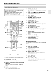
...H LISTENING MODE buttons (49) Used to control your DVD/BD player, CD player, and other components. K MUTING button (39) Mutes or unmutes the AV receiver. G SETUP button Used to turn speaker sets A and B on . 4 CH +/- J DISPLAY button (40) Displays information about the band, frequency, ...44) Displays information about the current input source. O SLEEP button (39) Used with the Sleep function. ■ Controlling the tuner To control the AV receiver's tuner, press the [AM], [FM] button. 1 Arrow [R]/[X] buttons Used to change settings. button (45) Selects radio presets. 5 Number ...
...H LISTENING MODE buttons (49) Used to control your DVD/BD player, CD player, and other components. K MUTING button (39) Mutes or unmutes the AV receiver. G SETUP button Used to turn speaker sets A and B on . 4 CH +/- J DISPLAY button (40) Displays information about the band, frequency, ...44) Displays information about the current input source. O SLEEP button (39) Used with the Sleep function. ■ Controlling the tuner To control the AV receiver's tuner, press the [AM], [FM] button. 1 Arrow [R]/[X] buttons Used to change settings. button (45) Selects radio presets. 5 Number ...
Owner Manual
Page 12
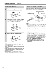
... damage from leakage or corrosion. 30° 30° Approx. 16 ft. (5 m) Notes: • The remote controller may not work reliably if the AV receiver is subjected to equipment that uses infrared rays, the remote controller may not work reliably. • Don't put anything on top of the same type... is used in the same room, or the AV receiver is installed in a rack behind colored glass doors. Keep this in mind when installing. • If another remote controller of the remote controller, such...
... damage from leakage or corrosion. 30° 30° Approx. 16 ft. (5 m) Notes: • The remote controller may not work reliably if the AV receiver is subjected to equipment that uses infrared rays, the remote controller may not work reliably. • Don't put anything on top of the same type... is used in the same room, or the AV receiver is installed in a rack behind colored glass doors. Keep this in mind when installing. • If another remote controller of the remote controller, such...

Owner Manual
Page 13
...Sub Room 1/3 wall length Surround left and right speakers. * While speaker set B is on , these speakers output no sound. Position them inward. AV receiver Remote controller or Speaker set A Speaker set A should be positioned facing the listener at the same height as shown. Tip: To find the best .... Ideally they should be used mainly for precise sound positioning and to your subwoofer, while playing a movie or some music with the AV receiver: speaker set A and speaker set B can use two sets of the LFE (Low-Frequency Effects) channel. For movies it close to ...
...Sub Room 1/3 wall length Surround left and right speakers. * While speaker set B is on , these speakers output no sound. Position them inward. AV receiver Remote controller or Speaker set A Speaker set A should be positioned facing the listener at the same height as shown. Tip: To find the best .... Ideally they should be used mainly for precise sound positioning and to your subwoofer, while playing a movie or some music with the AV receiver: speaker set A and speaker set B can use two sets of the LFE (Low-Frequency Effects) channel. For movies it close to ...

Owner Manual
Page 14
... surround-sound system, you should connect five speakers and a powered subwoofer. Connecting a Powered Subwoofer Using a suitable cable, connect the AV receiver's PRE OUT: SUBWOOFER to the positive (+) side of speakers you 're using banana plugs, tighten the speaker terminal before inserting the... directly into the center hole of 6 ohms or higher. FRONT SPEAKERS A OTHERS LINE INPUT LINE INPUT Attaching the Speaker Labels The AV receiver's positive (+) speaker terminals are color-coded for a long period of identification. (The negative (-) speaker terminals are color-coded and...
... surround-sound system, you should connect five speakers and a powered subwoofer. Connecting a Powered Subwoofer Using a suitable cable, connect the AV receiver's PRE OUT: SUBWOOFER to the positive (+) side of speakers you 're using banana plugs, tighten the speaker terminal before inserting the... directly into the center hole of 6 ohms or higher. FRONT SPEAKERS A OTHERS LINE INPUT LINE INPUT Attaching the Speaker Labels The AV receiver's positive (+) speaker terminals are color-coded for a long period of identification. (The negative (-) speaker terminals are color-coded and...

Owner Manual
Page 15
... right speaker left speaker Front right speaker A Front left speaker A Center speaker Speaker Set A Front right speaker B Front left speaker B Speaker Set B 15 Connecting the AV Receiver-Continued Connecting the Speaker Cables FRONT SPEAKERS A 1 Strip about 5/8" (15 mm) of insulation from the ends of the speaker cables, and twist the bare wires...
... right speaker left speaker Front right speaker A Front left speaker A Center speaker Speaker Set A Front right speaker B Front left speaker B Speaker Set B 15 Connecting the AV Receiver-Continued Connecting the Speaker Cables FRONT SPEAKERS A 1 Strip about 5/8" (15 mm) of insulation from the ends of the speaker cables, and twist the bare wires...

Owner Manual
Page 16
...ready for indoor use , you don't injure yourself when using it with the supplied indoor FM antenna, try using thumbtacks. 16 Connecting the AV Receiver-Continued Connecting Antenna This section explains how to connect the supplied indoor FM antenna and AM loop antenna, and how to achieve the best ... available outdoor FM and AM antennas. Keep the antenna as far away as possible from your AV receiver is for use, you must connect the antenna to the AM push terminals, as shown. The AV receiver won't pick up any radio signals without any antenna connected, so you 'll need to...
...ready for indoor use , you don't injure yourself when using it with the supplied indoor FM antenna, try using thumbtacks. 16 Connecting the AV Receiver-Continued Connecting Antenna This section explains how to connect the supplied indoor FM antenna and AM loop antenna, and how to achieve the best ... available outdoor FM and AM antennas. Keep the antenna as far away as possible from your AV receiver is for use, you must connect the antenna to the AM push terminals, as shown. The AV receiver won't pick up any radio signals without any antenna connected, so you 'll need to...

Owner Manual
Page 17
... be left connected. Outdoor antenna must be used in addition to the loop antenna, as shown. TV/FM antenna splitter To AV receiver To TV (or VCR) 17 Connecting the AV Receiver-Continued Connecting an Outdoor FM Antenna If you cannot achieve good reception with local regulations to prevent electrical shock hazards. ■ Using...
... be left connected. Outdoor antenna must be used in addition to the loop antenna, as shown. TV/FM antenna splitter To AV receiver To TV (or VCR) 17 Connecting the AV Receiver-Continued Connecting an Outdoor FM Antenna If you cannot achieve good reception with local regulations to prevent electrical shock hazards. ■ Using...

Owner Manual
Page 18
... and allows you 've completed and double-checked all the way to connect left-channel audio inputs and outputs (typically labeled "L"). Note: The AV receiver does not support SCART connections. 18 Video Component video cable Y PB/CB PR/CR Composite video cable Y PB/CB PR/CR Y CB/...quality. (Some TV manufacturers label their component video jacks slightly differently.) Composite video is the same as for coaxial. Optical Digital Jacks The AV receiver's optical digital jacks have shutter-type covers that open when an optical plug is the same as for optical. Use white plugs to ...
... and allows you 've completed and double-checked all the way to connect left-channel audio inputs and outputs (typically labeled "L"). Note: The AV receiver does not support SCART connections. 18 Video Component video cable Y PB/CB PR/CR Composite video cable Y PB/CB PR/CR Y CB/...quality. (Some TV manufacturers label their component video jacks slightly differently.) Composite video is the same as for coaxial. Optical Digital Jacks The AV receiver's optical digital jacks have shutter-type covers that open when an optical plug is the same as for optical. Use white plugs to ...

Owner Manual
Page 19
... the signal. HDMI sources are output only by the speakers connected to the AV receiver. AV receiver HDMI Optical HDMI TV, projector, etc. Video Connection Formats Video equipment can be connected to the AV receiver by using any of the following audio connection formats: analog, optical, coaxial,...an input selector (see page 15 for compatibility with a wide range of the following sections as the input will depend on the AV receiver. : Signal Flow Video Video Audio Audio DVD/BD player, etc. Which Connections Should I Use? Coaxial Analog Analog 19 For ...
... the signal. HDMI sources are output only by the speakers connected to the AV receiver. AV receiver HDMI Optical HDMI TV, projector, etc. Video Connection Formats Video equipment can be connected to the AV receiver by using any of the following audio connection formats: analog, optical, coaxial,...an input selector (see page 15 for compatibility with a wide range of the following sections as the input will depend on the AV receiver. : Signal Flow Video Video Audio Audio DVD/BD player, etc. Which Connections Should I Use? Coaxial Analog Analog 19 For ...
Owner Manual
Page 20
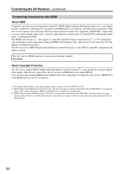
..., NEC, and Silicon Image, this open industry group's objective is a new digital interface standard for digital video signals. Connecting the AV Receiver-Continued Connecting Components with HDMI About HDMI Designed to meet the increased demands of digital audio (2-channel PCM, multichannel digital audio, or ...multichannel PCM). The AV receiver's HDMI interface is based on your TV or projector. *1 DVI (Digital Visual Interface): The digital display interface standard set -...
..., NEC, and Silicon Image, this open industry group's objective is a new digital interface standard for digital video signals. Connecting the AV Receiver-Continued Connecting Components with HDMI About HDMI Designed to meet the increased demands of digital audio (2-channel PCM, multichannel digital audio, or ...multichannel PCM). The AV receiver's HDMI interface is based on your TV or projector. *1 DVI (Digital Visual Interface): The digital display interface standard set -...
Owner Manual
Page 21
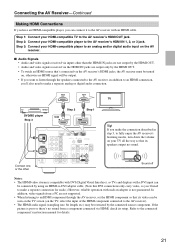
...a separate analog or digital audio connection. Step 2: Connect your HDMI-compatible player to the AV receiver's HDMI OUT jack. In addition, video signals from a component connected via the AV receiver's HDMI jacks, the AV receiver must be turned on, otherwise no HDMI signal will be output. • If you want...that's connected via HDMI, check its setup. Refer to make a separate connection for details. 21 Step 1: Connect your HDMI-compatible TV to the AV receiver's HDMI IN 1, 2, or 3 jack. If the picture is poor or there's no sound from a PC are output only by the connected...
...a separate analog or digital audio connection. Step 2: Connect your HDMI-compatible player to the AV receiver's HDMI OUT jack. In addition, video signals from a component connected via the AV receiver's HDMI jacks, the AV receiver must be turned on, otherwise no HDMI signal will be output. • If you want...that's connected via HDMI, check its setup. Refer to make a separate connection for details. 21 Step 1: Connect your HDMI-compatible TV to the AV receiver's HDMI IN 1, 2, or 3 jack. If the picture is poor or there's no sound from a PC are output only by the connected...

Owner Manual
Page 22
...and then make the connection. • With connection a , you can listen to and record audio from your VCR or cable or satellite receiver to TV programs through the AV receiver (see page 36) TV, projector, etc. If your TV has no audio outputs, connect an audio output from your TV. •...; To enjoy Dolby Digital and DTS, use its tuner to listen to the AV receiver and use connection b or c . Connection A B a b c AV receiver COMPONENT VIDEO OUT MONITOR OUT V TV/TAPE IN L/R DIGITAL IN COAXIAL (DVD/BD) DIGITAL IN OPTICAL 1 (CBL/SAT) Signal...
...and then make the connection. • With connection a , you can listen to and record audio from your VCR or cable or satellite receiver to TV programs through the AV receiver (see page 36) TV, projector, etc. If your TV has no audio outputs, connect an audio output from your TV. •...; To enjoy Dolby Digital and DTS, use its tuner to listen to the AV receiver and use connection b or c . Connection A B a b c AV receiver COMPONENT VIDEO OUT MONITOR OUT V TV/TAPE IN L/R DIGITAL IN COAXIAL (DVD/BD) DIGITAL IN OPTICAL 1 (CBL/SAT) Signal...

Owner Manual
Page 23
...outputs, be assigned (see page 36) VIDEO OUT L R AUDIO OUT Y PB PR COMPONENT VIDEO OUT DVD/BD player 23 Connection A B a b c AV receiver COMPONENT VIDEO IN 1 (DVD/BD) DVD/BD IN V DVD/BD IN L/R DIGITAL IN COAXIAL (DVD/BD) DIGITAL IN OPTICAL 1 (CBL/SAT) Signal ... video output Analog audio L/R output Digital coaxial output Digital optical output c A b CB a OPTICAL OUT COAXIAL OUT Connect one or the other Connection c must connect the AV receiver to your DVD/BD player ( A or B ), and then make the connection. • With connection a , you can listen to use a and b , or...
...outputs, be assigned (see page 36) VIDEO OUT L R AUDIO OUT Y PB PR COMPONENT VIDEO OUT DVD/BD player 23 Connection A B a b c AV receiver COMPONENT VIDEO IN 1 (DVD/BD) DVD/BD IN V DVD/BD IN L/R DIGITAL IN COAXIAL (DVD/BD) DIGITAL IN OPTICAL 1 (CBL/SAT) Signal ... video output Analog audio L/R output Digital coaxial output Digital optical output c A b CB a OPTICAL OUT COAXIAL OUT Connect one or the other Connection c must connect the AV receiver to your DVD/BD player ( A or B ), and then make the connection. • With connection a , you can listen to use a and b , or...

Owner Manual
Page 24
... Audio Connection Choose an audio connection that matches your VCR or DVR ( a , b , or c ), and then make the connection. Connection A B a b c AV receiver COMPONENT VIDEO IN 2 (CBL/SAT) VCR/DVR IN V VCR/DVR IN L/R DIGITAL IN COAXIAL (DVD/BD) DIGITAL IN OPTICAL 1 (CBL/SAT) Signal flow VCR or...b CB a Connect one or the other These connection must connect the AV receiver to your favorite TV programs via the AV receiver, which is useful if your TV with the same type of connection. Connecting the AV Receiver-Continued Connecting a VCR or DVR for Playback Hint! Step 1: Video ...
... Audio Connection Choose an audio connection that matches your VCR or DVR ( a , b , or c ), and then make the connection. Connection A B a b c AV receiver COMPONENT VIDEO IN 2 (CBL/SAT) VCR/DVR IN V VCR/DVR IN L/R DIGITAL IN COAXIAL (DVD/BD) DIGITAL IN OPTICAL 1 (CBL/SAT) Signal flow VCR or...b CB a Connect one or the other These connection must connect the AV receiver to your favorite TV programs via the AV receiver, which is useful if your TV with the same type of connection. Connecting the AV Receiver-Continued Connecting a VCR or DVR for Playback Hint! Step 1: Video ...


