
Owner Manual
Page 1
5.1ch Home Theater System HT-S3300 AV Receiver (HT-R380) Speaker Package (HTP-380) Front Speakers (SKF-380 L/R) Center Speaker (SKC-380/SKC-380C) Surround Speakers (SKR-380 L/R) Subwoofer (SKW-380) Instruction Manual Thank ... retain this manual will enable you for future reference. Please read this manual thoroughly before making connections and plugging in this manual for purchasing an Onkyo 5.1ch Home Theater System.
5.1ch Home Theater System HT-S3300 AV Receiver (HT-R380) Speaker Package (HTP-380) Front Speakers (SKF-380 L/R) Center Speaker (SKC-380/SKC-380C) Surround Speakers (SKR-380 L/R) Subwoofer (SKW-380) Instruction Manual Thank ... retain this manual will enable you for future reference. Please read this manual thoroughly before making connections and plugging in this manual for purchasing an Onkyo 5.1ch Home Theater System.

Owner Manual
Page 2
WARNING AVIS RISK OF ELECTRIC SHOCK RISQUE DE CHOC ELECTRIQUE DO NOT OPEN NE PAS OUVRIR The lightning flash with arrowhead symbol, within an equilateral triangle, is intended to alert the user to the presence of uninsulated "dangerous voltage" within an equilateral triangle is damaged, liquid has been spilled or objects have fallen into the apparatus through openings as they exit from the wall outlet and refer servicing to escape. Keep these instructions. 2. Do not use attachments/accessories specified by the manufacturer. 12. If the provided plug does not fit into ...
WARNING AVIS RISK OF ELECTRIC SHOCK RISQUE DE CHOC ELECTRIQUE DO NOT OPEN NE PAS OUVRIR The lightning flash with arrowhead symbol, within an equilateral triangle, is intended to alert the user to the presence of uninsulated "dangerous voltage" within an equilateral triangle is damaged, liquid has been spilled or objects have fallen into the apparatus through openings as they exit from the wall outlet and refer servicing to escape. Keep these instructions. 2. Do not use attachments/accessories specified by the manufacturer. 12. If the provided plug does not fit into ...

Owner Manual
Page 3
...try to radio communications. If this unit, use a soft cloth dampened with the instructions, may leave marks on the unit, contact your Onkyo dealer. 8. Don't use the unit for compliance could void the user's authority to provide reasonable protection against harmful interference in a particular ...Do not leave rubber or plastic items on this unit for User CAUTION: The user changes or modifications not expressly approved by your Onkyo dealer. 3. If water or any other chemical solvents, because they may cause harmful interference to correct the interference by turning the ...
...try to radio communications. If this unit, use a soft cloth dampened with the instructions, may leave marks on the unit, contact your Onkyo dealer. 8. Don't use the unit for compliance could void the user's authority to provide reasonable protection against harmful interference in a particular ...Do not leave rubber or plastic items on this unit for User CAUTION: The user changes or modifications not expressly approved by your Onkyo dealer. 3. If water or any other chemical solvents, because they may cause harmful interference to correct the interference by turning the ...
Owner Manual
Page 4
... or discon- Make sure you should only be an issue, in which neutralizes the magnetic field, thereby removing any of the following items: AV Receiver HT-R380 HT-R380 (➔ 7) Remote controller and two batteries (AA/R6) (➔ 5) Indoor FM antenna (➔ 18) AM loop antenna (➔ 18) * In catalogs and on...
... or discon- Make sure you should only be an issue, in which neutralizes the magnetic field, thereby removing any of the following items: AV Receiver HT-R380 HT-R380 (➔ 7) Remote controller and two batteries (AA/R6) (➔ 5) Indoor FM antenna (➔ 18) AM loop antenna (➔ 18) * In catalogs and on...

Owner Manual
Page 5
Remote control sensor AV receiver Introduction Important Safety Instructions 2 Precautions 3 Speaker Precautions 4 Package Contents 4 Features 6 Front & Rear Panels 7 Speaker Package 9 Remote Controller 10 About Home Theater 11 Connections Connecting the AV Receiver 12 Turning On & Basic Operations Turning On/Off the AV Receiver 20 Basic Operations 21 Listening to the Radio 23 Recording 26 Using the Listening Modes 27 Advanced Operations Advanced Setup 30 Approx. 16 ft. (5 m) Controlling iPod & Other Components Controlling iPod 40 Controlling Other Components 44 Others ...
Remote control sensor AV receiver Introduction Important Safety Instructions 2 Precautions 3 Speaker Precautions 4 Package Contents 4 Features 6 Front & Rear Panels 7 Speaker Package 9 Remote Controller 10 About Home Theater 11 Connections Connecting the AV Receiver 12 Turning On & Basic Operations Turning On/Off the AV Receiver 20 Basic Operations 21 Listening to the Radio 23 Recording 26 Using the Listening Modes 27 Advanced Operations Advanced Setup 30 Approx. 16 ft. (5 m) Controlling iPod & Other Components Controlling iPod 40 Controlling Other Components 44 Others ...

Owner Manual
Page 6
... 192 kHz/24-bit D/A Converters • Powerful and Highly Accurate 32-bit Processing DSP • 3 HDMI*4 Inputs and 1 Output • Onkyo Q for System Control • 3 Digital Inputs (2 Optical/1 Coaxial) • Component Video Switching (2 Inputs/1 Output) • Universal Port for ...full-range speaker • Gloss Finished • Max. To receive HD Radio broadcasts, you must install an Onkyo UP-HT1 HD Radio tuner module (sold separately). *6 Manufactured under U.S. Features AV Receiver HT-R380 • 110 Watts/Channel @ 6 ohms • 120 Watts/Channel @ 6 ohms (JEITA) &#...
... 192 kHz/24-bit D/A Converters • Powerful and Highly Accurate 32-bit Processing DSP • 3 HDMI*4 Inputs and 1 Output • Onkyo Q for System Control • 3 Digital Inputs (2 Optical/1 Coaxial) • Component Video Switching (2 Inputs/1 Output) • Universal Port for ...full-range speaker • Gloss Finished • Max. To receive HD Radio broadcasts, you must install an Onkyo UP-HT1 HD Radio tuner module (sold separately). *6 Manufactured under U.S. Features AV Receiver HT-R380 • 110 Watts/Channel @ 6 ohms • 120 Watts/Channel @ 6 ohms (JEITA) &#...

Owner Manual
Page 7
The page numbers in parentheses show where you can find the main explanation for clarity. They are not shown here for each item. Front & Rear Panels Front Panel North American models B C DEF G H I LISTENING MODE buttons (➔ 27) J DIMMER button (North American models) (➔ 21) K MEMORY button (➔ 24) L TUNING MODE button (➔ 23) M DISPLAY button (➔ 21) N SETUP button (➔ 30) O TUNING, PRESET (➔ 23 to 24), arrow and ENTER buttons P RETURN button Q MASTER VOLUME control (➔ 21) R MUSIC OPTIMIZER button (➔ 21, 38) S PHONES jack ...
The page numbers in parentheses show where you can find the main explanation for clarity. They are not shown here for each item. Front & Rear Panels Front Panel North American models B C DEF G H I LISTENING MODE buttons (➔ 27) J DIMMER button (North American models) (➔ 21) K MEMORY button (➔ 24) L TUNING MODE button (➔ 23) M DISPLAY button (➔ 21) N SETUP button (➔ 30) O TUNING, PRESET (➔ 23 to 24), arrow and ENTER buttons P RETURN button Q MASTER VOLUME control (➔ 21) R MUSIC OPTIMIZER button (➔ 21, 38) S PHONES jack ...

Owner Manual
Page 8
Display BC D EF G H I SUBWOOFER terminals J SPEAKERS terminals (SURR, CENTER) K FRONT SPEAKERS B terminals L Power cord M V REMOTE CONTROL jack N Composite video and analog audio jacks (BD/DVD IN, VCR/DVR IN and OUT, CBL/SAT IN, GAME IN, TV/CD IN) See "Connecting the AV Receiver" for connection information (➔ 12 to 19). B A and B speaker indicators (➔ 11, 22) C Audio input indicators D Listening mode and format indicators (➔ 21, 27) E Audyssey indicators (➔ 34, 38) F Tuning indicators (➔ 23) Rear Panel G RDS indicator (excluding North American models...
Display BC D EF G H I SUBWOOFER terminals J SPEAKERS terminals (SURR, CENTER) K FRONT SPEAKERS B terminals L Power cord M V REMOTE CONTROL jack N Composite video and analog audio jacks (BD/DVD IN, VCR/DVR IN and OUT, CBL/SAT IN, GAME IN, TV/CD IN) See "Connecting the AV Receiver" for connection information (➔ 12 to 19). B A and B speaker indicators (➔ 11, 22) C Audio input indicators D Listening mode and format indicators (➔ 21, 27) E Audyssey indicators (➔ 34, 38) F Tuning indicators (➔ 23) Rear Panel G RDS indicator (excluding North American models...

Owner Manual
Page 9
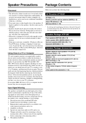
See "Wall Mounting" for easy speaker. Caution • The front grilles are not designed to be used to wall-mount the the HT-R380 with the supplied speaker cables. identification. En 9 Speaker Package Front, Center, Surround Speakers and Subwoofer (SKF-380, SKC-380/SKC-380C, SKR-380, SKW-...
See "Wall Mounting" for easy speaker. Caution • The front grilles are not designed to be used to wall-mount the the HT-R380 with the supplied speaker cables. identification. En 9 Speaker Package Front, Center, Surround Speakers and Subwoofer (SKF-380, SKC-380/SKC-380C, SKR-380, SKW-...

Owner Manual
Page 10
...) En 10 K For detailed information, see the pages in parentheses. E B ON/STANDBY button (➔ 20) L C REMOTE MODE/INPUT SELECTOR buttons (➔ 21, 44 to control D Onkyo Blu-ray Disc/DVD player, CD player, and other components. You can also use the remote controller to 45) F D TONE, + and - J You can select AM...
...) En 10 K For detailed information, see the pages in parentheses. E B ON/STANDBY button (➔ 20) L C REMOTE MODE/INPUT SELECTOR buttons (➔ 21, 44 to control D Onkyo Blu-ray Disc/DVD player, CD player, and other components. You can also use the remote controller to 45) F D TONE, + and - J You can select AM...

Owner Manual
Page 11
... bass output from the TV. Position it 's used for dialog. With analog or digital TV, you can enjoy Dolby Pro Logic II, DTS Neo:6, or Onkyo's original DSP listening modes. E Subwoofer (SKW-380) The subwoofer handles the bass sounds of wall position D E Speakers B: Sub Room B Front speakers (SKF-380) These output...
... bass output from the TV. Position it 's used for dialog. With analog or digital TV, you can enjoy Dolby Pro Logic II, DTS Neo:6, or Onkyo's original DSP listening modes. E Subwoofer (SKW-380) The subwoofer handles the bass sounds of wall position D E Speakers B: Sub Room B Front speakers (SKF-380) These output...

Owner Manual
Page 12
Connecting the AV Receiver Connecting Your Speakers Speaker Configuration The following before making any connections. • Read the instructions supplied with the AV receiver's rear panel. For 5.1-channel surround-sound playback, you have contact with your speakers. • Pay close attention to each speaker terminal. Number of speakers that you need to several terminals. Connecting the Speaker Cables The AV receiver's positive (+) speaker terminals are all black.) Speaker Front left Front right Center Surround left Surround right Subwoofer Color White Red Green Blue Gray...
Connecting the AV Receiver Connecting Your Speakers Speaker Configuration The following before making any connections. • Read the instructions supplied with the AV receiver's rear panel. For 5.1-channel surround-sound playback, you have contact with your speakers. • Pay close attention to each speaker terminal. Number of speakers that you need to several terminals. Connecting the Speaker Cables The AV receiver's positive (+) speaker terminals are all black.) Speaker Front left Front right Center Surround left Surround right Subwoofer Color White Red Green Blue Gray...

Owner Manual
Page 13
Surround Surround right left speaker speaker Center speaker Gray Blue Green Red White Purple Front right Front left speaker A speaker A Speakers A Subwoofer Front right speaker B Front left speaker B Speakers B En 13 Push-type speaker terminals Strip 3/8" to 1/2" (10 to 12 mm) of insulation from the ends of the speaker cables, and twist the bare wires tightly, as shown. (Supplied speaker cables are already stripped.) 1/2" to 5/8" (12 to 15 mm) Using Banana Plugs (North American models) • If you are already stripped.) 3/8" to 1/2" (10 to 12 mm) The following ...
Surround Surround right left speaker speaker Center speaker Gray Blue Green Red White Purple Front right Front left speaker A speaker A Speakers A Subwoofer Front right speaker B Front left speaker B Speakers B En 13 Push-type speaker terminals Strip 3/8" to 1/2" (10 to 12 mm) of insulation from the ends of the speaker cables, and twist the bare wires tightly, as shown. (Supplied speaker cables are already stripped.) 1/2" to 5/8" (12 to 15 mm) Using Banana Plugs (North American models) • If you are already stripped.) 3/8" to 1/2" (10 to 12 mm) The following ...

Owner Manual
Page 14
Front speakers (SKF-380) Keyhole slot for a More Stable Platform We recommend using the keyhole slots. low walls, use suitable wall anchors. • Use screws with a head diameter of 5/16" (9 mm) or less and a shank diameter of each speaker on two screws that are solid, use a cable/pipe detector to the wall. Wall Mounting The speakers can easily be wall mounted by using the provided rubber stoppers to hang each speaker on a screw that you have hollow Pad walls, screw each mounting screw into the wall. To mount the front or surround speakers vertically, use the two ...
Front speakers (SKF-380) Keyhole slot for a More Stable Platform We recommend using the keyhole slots. low walls, use suitable wall anchors. • Use screws with a head diameter of 5/16" (9 mm) or less and a shank diameter of each speaker on two screws that are solid, use a cable/pipe detector to the wall. Wall Mounting The speakers can easily be wall mounted by using the provided rubber stoppers to hang each speaker on a screw that you have hollow Pad walls, screw each mounting screw into the wall. To mount the front or surround speakers vertically, use the two ...

Owner Manual
Page 15
tions). • To prevent interference, keep audio and video cables away from power cords and speaker cables. Signal Video and Audio Video Audio Cable HDMI Component video Y PB/CB PR/CR Composite video Optical digital audio Coaxial digital audio Analog audio (RCA) 1/8" (3.5 mm) Stereo mini plug Jack HDMI Green Blue Red Description HDMI connections can cause noise or malfunc- Component video separates the luminance (Y) and color difference signals (PR, PB), providing the best picture quality (some TV manufacturers label their component video sockets slightly differently)....
tions). • To prevent interference, keep audio and video cables away from power cords and speaker cables. Signal Video and Audio Video Audio Cable HDMI Component video Y PB/CB PR/CR Composite video Optical digital audio Coaxial digital audio Analog audio (RCA) 1/8" (3.5 mm) Stereo mini plug Jack HDMI Green Blue Red Description HDMI connections can cause noise or malfunc- Component video separates the luminance (Y) and color difference signals (PR, PB), providing the best picture quality (some TV manufacturers label their component video sockets slightly differently)....

Owner Manual
Page 16
Note • When listening to an HDMI component through the AV receiver, set to "On" (➔ 37) to hear from the AV receiver's speakers, too. To stop the AV receiver's speakers producing sound, change the settings, change your TV's settings, or turn down the AV receiver's volume. ■ Audio return channel (ARC) function Audio return channel (ARC) function enables an HDMI capable TV to send the audio stream to the HDMI OUT of Q-compatible TV, by controlling the AV receiver's volume, the AV receiver's speakers will be output from speakers of the AV receiver. The default ...
Note • When listening to an HDMI component through the AV receiver, set to "On" (➔ 37) to hear from the AV receiver's speakers, too. To stop the AV receiver's speakers producing sound, change the settings, change your TV's settings, or turn down the AV receiver's volume. ■ Audio return channel (ARC) function Audio return channel (ARC) function enables an HDMI capable TV to send the audio stream to the HDMI OUT of Q-compatible TV, by controlling the AV receiver's volume, the AV receiver's speakers will be output from speakers of the AV receiver. The default ...

Owner Manual
Page 17
Connecting External Components The on-screen setup menus appear only on the front panel Portable audio player Analog audio line output (➔ 15) En 17 To make a connection for details. You can be sure to connect the main stereo output using connection $. See your phono equalizer's manual for details. • With connection #, you can enjoy Dolby Digital and DTS. • If your turntable's manual for video recording (➔ 26). If your TV is connected to the appropriate jacks. Game console Analog audio TV, CD player, Turntable*1 Cassette tape deck, MD, CD-R ...
Connecting External Components The on-screen setup menus appear only on the front panel Portable audio player Analog audio line output (➔ 15) En 17 To make a connection for details. You can be sure to connect the main stereo output using connection $. See your phono equalizer's manual for details. • With connection #, you can enjoy Dolby Digital and DTS. • If your turntable's manual for video recording (➔ 26). If your TV is connected to the appropriate jacks. Game console Analog audio TV, CD player, Turntable*1 Cassette tape deck, MD, CD-R ...

Owner Manual
Page 18
...jack is ready for V connections. Assembling the AM loop antenna Thumbtacks, etc. You must connect the antenna to the AV receiver. Connecting other Onkyo components. Insert wire. Tip • If you 'll need to tune into a radio station and position the antenna to achieve the best... (supplied) AM loop antenna (supplied) Note • Once your AV receiver is for connecting additional V-capable components. • Connect only Onkyo components to connect the supplied indoor FM antenna and AM loop antenna. Step 3: If you cannot achieve good reception with the supplied indoor AM...
...jack is ready for V connections. Assembling the AM loop antenna Thumbtacks, etc. You must connect the antenna to the AV receiver. Connecting other Onkyo components. Insert wire. Tip • If you 'll need to tune into a radio station and position the antenna to achieve the best... (supplied) AM loop antenna (supplied) Note • Once your AV receiver is for connecting additional V-capable components. • Connect only Onkyo components to connect the supplied indoor FM antenna and AM loop antenna. Step 3: If you cannot achieve good reception with the supplied indoor AM...

Owner Manual
Page 19
Note The on the formats supported by the analog VCR/DVR OUT. Composite Component IN HDMI AV receiver Composite MONITOR OUT Component HDMI Audio Connection Formats Audio component can be connected by using any one input, the inputs will be connected by using any of the following video connection formats: composite video, component video, or HDMI, the latter offering the best picture quality. When choosing a connection format, bear in mind that the AV receiver does not convert digital input signals for compatibility with a wide range of priority: HDMI, digital, analog. ...
Note The on the formats supported by the analog VCR/DVR OUT. Composite Component IN HDMI AV receiver Composite MONITOR OUT Component HDMI Audio Connection Formats Audio component can be connected by using any one input, the inputs will be connected by using any of the following video connection formats: composite video, component video, or HDMI, the latter offering the best picture quality. When choosing a connection format, bear in mind that the AV receiver does not convert digital input signals for compatibility with a wide range of priority: HDMI, digital, analog. ...

Owner Manual
Page 20
The AV receiver will enter Standby mode. To prevent any loud surprises when you turn on the AV receiver, always turn down the volume before you turn it off . Turning Off Press ON/STANDBY on the remote controller. En 20 or Press RECEIVER followed by ON/STANDBY on the front panel or the remote controller. The AV receiver comes on the front panel. Turning On/Off the AV Receiver ON/STANDBY STANDBY indicator ON/STANDBY RECEIVER Front panel Remote controller Turning On Press ON/STANDBY on , the display lights, and the STANDBY indicator goes off .
The AV receiver will enter Standby mode. To prevent any loud surprises when you turn on the AV receiver, always turn down the volume before you turn it off . Turning Off Press ON/STANDBY on the remote controller. En 20 or Press RECEIVER followed by ON/STANDBY on the front panel or the remote controller. The AV receiver comes on the front panel. Turning On/Off the AV Receiver ON/STANDBY STANDBY indicator ON/STANDBY RECEIVER Front panel Remote controller Turning On Press ON/STANDBY on , the display lights, and the STANDBY indicator goes off .
