
English Manual
Page 1
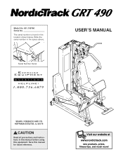
Visit our website at www.nordictrack.com new products, prizes, fitness tips, and much more! Serial Number Decal USER'S MANUAL SEARS, ROEBUCK AND CO. HOFFMAN ESTATES, IL 60179 CAUTION Read all precautions and instructions in the space above. Model No. 831.159760 Serial No. Write the serial number in this manual before using this manual for future reference. Save this equipment. The serial number is found in the location shown below.
Visit our website at www.nordictrack.com new products, prizes, fitness tips, and much more! Serial Number Decal USER'S MANUAL SEARS, ROEBUCK AND CO. HOFFMAN ESTATES, IL 60179 CAUTION Read all precautions and instructions in the space above. Model No. 831.159760 Serial No. Write the serial number in this manual before using this manual for future reference. Save this equipment. The serial number is found in the location shown below.
English Manual
Page 2
Table of Contents Important Precautions 3 Before You Begin 4 Assembly 5 Cable Diagram 21 Adjustment 22 Trouble-Shooting And Maintenance 24 Weight Resistance Chart 25 Exercise Guidelines 26 Ordering Replacement Parts Back Cover Full 90 Day Warranty Back Cover Note: A PART LIST/EXPLODED DRAWING and a PART IDENTIFICATION CHART are attached in the center of ICON Health & Fitness, Inc. 2 NordicTrack is a registered trademark of this manual.
Table of Contents Important Precautions 3 Before You Begin 4 Assembly 5 Cable Diagram 21 Adjustment 22 Trouble-Shooting And Maintenance 24 Weight Resistance Chart 25 Exercise Guidelines 26 Ordering Replacement Parts Back Cover Full 90 Day Warranty Back Cover Note: A PART LIST/EXPLODED DRAWING and a PART IDENTIFICATION CHART are attached in the center of ICON Health & Fitness, Inc. 2 NordicTrack is a registered trademark of this manual.
English Manual
Page 3
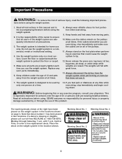
... of the owner to ensure that does not use only. Read all precautions. 3. Cover the floor or carpet beneath the weight system to order a free replacement decal. If the cables bind while you use of all instructions in this manual and in two locations. Always disconnect the lat bar from the weight system when performing an exercise that all users of the weight system are exercising, stop immediately and...
... of the owner to ensure that does not use only. Read all precautions. 3. Cover the floor or carpet beneath the weight system to order a free replacement decal. If the cables bind while you use of all instructions in this manual and in two locations. Always disconnect the lat bar from the weight system when performing an exercise that all users of the weight system are exercising, stop immediately and...
English Manual
Page 4
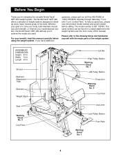
... group of this manual carefully before calling. ASSEMBLED DIMENSIONS: Height: 81 in . Shroud Backrest Adjustment Tube Backrest Weight Stack Seat Warning Decal No. 2 Leg Press Lat Bar High Pulley Station Warning Decal No. 1 AB Pulley Station Press Arm Warning Decal No. 3 Curl Pad Leg Lever Low Pulley Station Foot Plate Warning Decal No. 1 4 until 7 p.m. The serial number can be found on a decal attached to tone your body, build dramatic muscle...
... group of this manual carefully before calling. ASSEMBLED DIMENSIONS: Height: 81 in . Shroud Backrest Adjustment Tube Backrest Weight Stack Seat Warning Decal No. 2 Leg Press Lat Bar High Pulley Station Warning Decal No. 1 AB Pulley Station Press Arm Warning Decal No. 3 Curl Pad Leg Lever Low Pulley Station Foot Plate Warning Decal No. 1 4 until 7 p.m. The serial number can be found on a decal attached to tone your body, build dramatic muscle...
English Manual
Page 5
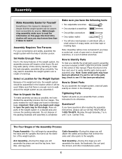
... leg lever, handles, and leg press. Place all parts exactly as possible, we have included a PART IDENTIFICATION CHART in the center of another person. Arm Assembly-During this stage you have a socket set, a set of open the parts bag for each assembly step. Make sure you will attach the cables and pulleys that connect the arms and other miscellaneous parts. 5 Cable Assembly-During this stage you have the following tools: • Two adjustable...
... leg lever, handles, and leg press. Place all parts exactly as possible, we have included a PART IDENTIFICATION CHART in the center of another person. Arm Assembly-During this stage you have a socket set, a set of open the parts bag for each assembly step. Make sure you will attach the cables and pulleys that connect the arms and other miscellaneous parts. 5 Cable Assembly-During this stage you have the following tools: • Two adjustable...
English Manual
Page 6
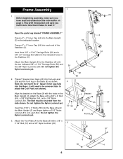
... brief introduction will need to be inserted from the side shown. Front Leg 3. Do not tighten the Nylon Locknut yet. 65 29 50 55 Insert two 5/16" x 3" Bolts (78) into the Base; Do not tighten the Nylon Locknuts yet. Frame Assembly 1 24 1. Attach the Main Upright (3) to read and understood the information on the Base (8) with a 3/8" x 4" Bolt (65), a 3/8" Flat Washer...
... brief introduction will need to be inserted from the side shown. Front Leg 3. Do not tighten the Nylon Locknut yet. 65 29 50 55 Insert two 5/16" x 3" Bolts (78) into the Base; Do not tighten the Nylon Locknuts yet. Frame Assembly 1 24 1. Attach the Main Upright (3) to read and understood the information on the Base (8) with a 3/8" x 4" Bolt (65), a 3/8" Flat Washer...
English Manual
Page 8
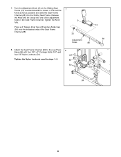
... it snap into the Sliding Seat Frame. Turn the Adjustment Knob (9) on the Sliding Seat Frame (74) counterclockwise to the Leg Press Base (84) with four 3/8" x 3" Carriage Bolts (107) and four 3/8" Nylon Locknuts (50). Tighten the Knob 9 fully. 74 Press a 2" Square Inner Cap (33) and an Angle Cap (99) onto the indicated ends of the adjustment holes in steps 1-2. 8 107 88 50 107...
... it snap into the Sliding Seat Frame. Turn the Adjustment Knob (9) on the Sliding Seat Frame (74) counterclockwise to the Leg Press Base (84) with four 3/8" x 3" Carriage Bolts (107) and four 3/8" Nylon Locknuts (50). Tighten the Knob 9 fully. 74 Press a 2" Square Inner Cap (33) and an Angle Cap (99) onto the indicated ends of the adjustment holes in steps 1-2. 8 107 88 50 107...
English Manual
Page 11
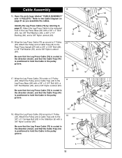
... Locknut (50). Cable Assembly 15 15. Open the parts bags labeled "CABLE ASSEMBLY" and "4 PULLEYS." Be sure that the Leg Press Cable (76) is routed in the direction shown, and that the Cable Trap (44) 84 is positioned to the 3/8" x 5" Carriage Bolt (82) in the pulley groove. 50 55 18 50 35 44 76 82 5 92 35 44 76 11 Attach the Leg Press Cable to the Cable Diagram on page...
... Locknut (50). Cable Assembly 15 15. Open the parts bags labeled "CABLE ASSEMBLY" and "4 PULLEYS." Be sure that the Leg Press Cable (76) is routed in the direction shown, and that the Cable Trap (44) 84 is positioned to the 3/8" x 5" Carriage Bolt (82) in the pulley groove. 50 55 18 50 35 44 76 82 5 92 35 44 76 11 Attach the Leg Press Cable to the Cable Diagram on page...
English Manual
Page 12
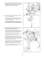
... Pulley Bracket (91). 20 Attach the end of the Leg Press Cable (76) to the 19 welded bracket on the other end. 21 Feed the end of the Cable through the Main Upright and the Pulley. Slide another 5/8" x 1/2" Pulley Bushing (42) and 3/8" Flat Washer (55) onto the 3/8" x 2 1/2" Bolt (54). Remove the pre-assembled 4" Pulley (not shown) from the Press Frame (12), and set them aside. Bolt...
... Pulley Bracket (91). 20 Attach the end of the Leg Press Cable (76) to the 19 welded bracket on the other end. 21 Feed the end of the Cable through the Main Upright and the Pulley. Slide another 5/8" x 1/2" Pulley Bushing (42) and 3/8" Flat Washer (55) onto the 3/8" x 2 1/2" Bolt (54). Remove the pre-assembled 4" Pulley (not shown) from the Press Frame (12), and set them aside. Bolt...
English Manual
Page 15
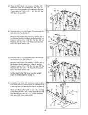
...attached in the direction shown and attach the Pulley to the Leg Press Cable (76), with a 3/8" x 2 1/2" Bolt (54), two 3/8" Flat Washers (55), two 5/8" x 1/2" Pulley Bushings (42), and a 3/8" Nylon Jamnut (63). 73 91 60 76 29 63 35 73 1 55 42 55 54 30. Route the Low Cable through the indicated slots in the Leg Lever (29) and the front leg on the High Cable... Cable (73) hang over the weight stack; Locate the Low Cable (72), which has a ball on the High Cable (73) up through 30 the next slot in the Top Frame (1). 42 Wrap the High Cable (73) around a 4" Pulley (35) in step ...
...attached in the direction shown and attach the Pulley to the Leg Press Cable (76), with a 3/8" x 2 1/2" Bolt (54), two 3/8" Flat Washers (55), two 5/8" x 1/2" Pulley Bushings (42), and a 3/8" Nylon Jamnut (63). 73 91 60 76 29 63 35 73 1 55 42 55 54 30. Route the Low Cable through the indicated slots in the Leg Lever (29) and the front leg on the High Cable... Cable (73) hang over the weight stack; Locate the Low Cable (72), which has a ball on the High Cable (73) up through 30 the next slot in the Top Frame (1). 42 Wrap the High Cable (73) around a 4" Pulley (35) in step ...
English Manual
Page 18
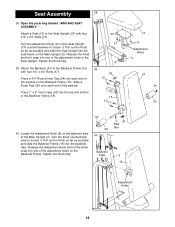
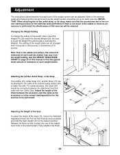
... Upright (3). Turn the Knob counterclockwise to loosen it. Tighten the Knob fully. 34 30 40 Backrest Tube 43 Pad Bar 3 15 9 Adjustment Holes 18 Attach the Backrest (41) to the Seat Upright (37) with four 1/4" x 3/4" Bolts (17). Open the parts bag labeled "ARM AND SEAT ASSEMBLY." Release the Knob and let it . Slide a Foam Pad (30) onto each end of the adjustment holes in the Seat Upright. Turn the Adjustment Knob (9) on the Seat Upright...
... Upright (3). Turn the Knob counterclockwise to loosen it. Tighten the Knob fully. 34 30 40 Backrest Tube 43 Pad Bar 3 15 9 Adjustment Holes 18 Attach the Backrest (41) to the Seat Upright (37) with four 1/4" x 3/4" Bolts (17). Open the parts bag labeled "ARM AND SEAT ASSEMBLY." Release the Knob and let it . Slide a Foam Pad (30) onto each end of the adjustment holes in the Seat Upright. Turn the Adjustment Knob (9) on the Seat Upright...
English Manual
Page 20
... of the Lat Bar (61). 47 103 32 56 61 32 32 103 48. Do not tighten the Bolts yet. 45 "L"-Brackets Align Corners 1 71 17 17 71 25 56 46. Attach the Curl Pad (21) to make sure that all parts have been properly tight- The use of the cables does not move smoothly over the pulleys. The Screws must...
... of the Lat Bar (61). 47 103 32 56 61 32 32 103 48. Do not tighten the Bolts yet. 45 "L"-Brackets Align Corners 1 71 17 17 71 25 56 46. Attach the Curl Pad (21) to make sure that all parts have been properly tight- The use of the cables does not move smoothly over the pulleys. The Screws must...
English Manual
Page 22
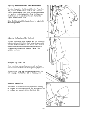
... attaching the lat bar, ankle strap, or ab strap, make sure that it snaps into one of resistance at the desired pulley station with two Cable Clips. Release the Knob so that the accessories are in the correct starting position for the exercise to find the approx- 26 imate amount of the adjustment holes in increments of the exercise will be performed. Use the WEIGHT RESISTANCE CHART...
... attaching the lat bar, ankle strap, or ab strap, make sure that it snaps into one of resistance at the desired pulley station with two Cable Clips. Release the Knob so that the accessories are in the correct starting position for the exercise to find the approx- 26 imate amount of the adjustment holes in increments of the exercise will be performed. Use the WEIGHT RESISTANCE CHART...
English Manual
Page 23
...Backrest (41), first loosen the Adjustment Knob (9). To lock the Leg Lever (29), turn the Leg Lever Lock (11) until it with the Leg Lever (29) locked. Attaching the Curl Pad Remove the 2" Square Inner Cap (33) from the front leg on the Press Arm (46), unscrew the Adjustment Knob (9) until it engages the ...Handles (20) should always be performed more comfortably with the Curl Knob (89). 23 29 11 28 89 83 33 8 Tighten the Adjustment Knob. Fully retighten the Knob. 9 46 9 20 20 41 Using the Leg Lever Lock Some exercises, such as possible and slide the Backrest Frame (not shown) ...
...Backrest (41), first loosen the Adjustment Knob (9). To lock the Leg Lever (29), turn the Leg Lever Lock (11) until it with the Leg Lever (29) locked. Attaching the Curl Pad Remove the 2" Square Inner Cap (33) from the front leg on the Press Arm (46), unscrew the Adjustment Knob (9) until it engages the ...Handles (20) should always be performed more comfortably with the Curl Knob (89). 23 29 11 28 89 83 33 8 Tighten the Adjustment Knob. Fully retighten the Knob. 9 46 9 20 20 41 Using the Leg Lever Lock Some exercises, such as possible and slide the Backrest Frame (not shown) ...
English Manual
Page 24
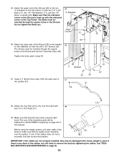
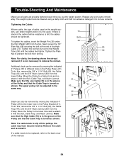
... the High Cable (73) is in the cables before resistance is turned as shown. Tighten the Plain Nut to remove the shroud. 68 26 39 Additional slack can stretch slightly when it with the Bolt, Cable Trap, and Nylon Jamnut. Trouble-Shooting And Maintenance Make sure all parts are properly tightened each time you use solvents. Move the Pulley to slip off the pulleys, the cable may have...
... the High Cable (73) is in the cables before resistance is turned as shown. Tighten the Plain Nut to remove the shroud. 68 26 39 Additional slack can stretch slightly when it with the Bolt, Cable Trap, and Nylon Jamnut. Trouble-Shooting And Maintenance Make sure all parts are properly tightened each time you use solvents. Move the Pulley to slip off the pulleys, the cable may have...
English Manual
Page 25
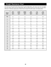
Weight Resistance Chart This chart shows the approximate weight resistance at each weight station. top weight. weight plates. "Top" refers to the 10 lb. The other numbers refer to the 10 lb. Weight Plates Top 1 2 3 4 5 6 7 8 9 10 11 12 13 14 15 16 17 18 19 Arm Press (lbs.) 24 35 46 57 68 79 90 102 113 124...219 231 Leg Press (lbs.) 28 51 74 97 120 143 167 190 213 236 259 282 305 328 351 374 397 420 443 466 25 Note: The actual resistance at each station may vary due to differences in individual weight plates as well as friction between the cables, pulleys, and weight guides.
Weight Resistance Chart This chart shows the approximate weight resistance at each weight station. top weight. weight plates. "Top" refers to the 10 lb. The other numbers refer to the 10 lb. Weight Plates Top 1 2 3 4 5 6 7 8 9 10 11 12 13 14 15 16 17 18 19 Arm Press (lbs.) 24 35 46 57 68 79 90 102 113 124...219 231 Leg Press (lbs.) 28 51 74 97 120 143 167 190 213 236 259 282 305 328 351 374 397 420 443 466 25 Note: The actual resistance at each station may vary due to differences in individual weight plates as well as friction between the cables, pulleys, and weight guides.
English Manual
Page 26
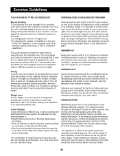
... weight training and aerobic exercise for each week to give your body time to regenerate. EXERCISE FORM Maintaining proper form is important. Proper breathing is an essential part of an effective exercise program. This requires moving only the appropriate parts of the body. It is the highest. If you feeling exhausted. Warming up . Schedule your workouts for 1 minute after each set . On the exercise guide accompanying this manual...
... weight training and aerobic exercise for each week to give your body time to regenerate. EXERCISE FORM Maintaining proper form is important. Proper breathing is an essential part of an effective exercise program. This requires moving only the appropriate parts of the body. It is the highest. If you feeling exhausted. Warming up . Schedule your workouts for 1 minute after each set . On the exercise guide accompanying this manual...
English Manual
Page 27
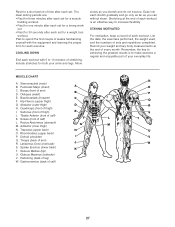
... for 30 seconds after each set for a weight loss workout. COOLING DOWN End each stretch gradually and go only as far as you can without strain. List the date, the exercises performed, the weight used, and the numbers of calf) N O P Q R S T U V W 27 Record your weight and key body measurements at the end of each exercise. MUSCLE CHART A. Pectoralis Major (chest) A C. Biceps (front of every month...
... for 30 seconds after each set for a weight loss workout. COOLING DOWN End each stretch gradually and go only as far as you can without strain. List the date, the exercises performed, the weight used, and the numbers of calf) N O P Q R S T U V W 27 Record your weight and key body measurements at the end of each exercise. MUSCLE CHART A. Pectoralis Major (chest) A C. Biceps (front of every month...
English Manual
Page 31
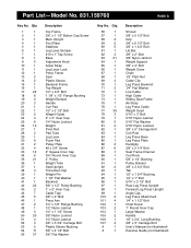
... Ab Strap Leg Press Cable Weight Insert 5/16" x 3" Bolt 5/16" Nylon Jamnut 5/16" Flat Washer 5/16" Nylon Locknut 3/8" x 5" Carriage Bolt Curl Post Leg Press Base Leg Press Plate Handgrip 3/8" x 3 1/4" Bolt Seat Frame Channel Curl Knob 5/8" x 1/4" Bushing Pulley Bracket 3/8" x 3 3/4" Bolt Tab 1/2" x 1 3/4" Bushing 1/4" x 1" Bolt 5/16" x 2 1/2" Bolt Rear Leg Press Upright Forward Leg Press Upright Angle Cap Leg Press Attachment 1/4" x 1 1/2" Bolt Chart Decal 1" Round Inner Cap Large Washer Handle 1/2" x 3/4" Long Bushing 3/8" x 3" Carriage Bolt User's Manual (not illustrated) Exercise Guide (not...
... Ab Strap Leg Press Cable Weight Insert 5/16" x 3" Bolt 5/16" Nylon Jamnut 5/16" Flat Washer 5/16" Nylon Locknut 3/8" x 5" Carriage Bolt Curl Post Leg Press Base Leg Press Plate Handgrip 3/8" x 3 1/4" Bolt Seat Frame Channel Curl Knob 5/8" x 1/4" Bushing Pulley Bracket 3/8" x 3 3/4" Bolt Tab 1/2" x 1 3/4" Bushing 1/4" x 1" Bolt 5/16" x 2 1/2" Bolt Rear Leg Press Upright Forward Leg Press Upright Angle Cap Leg Press Attachment 1/4" x 1 1/2" Bolt Chart Decal 1" Round Inner Cap Large Washer Handle 1/2" x 3/4" Long Bushing 3/8" x 3" Carriage Bolt User's Manual (not illustrated) Exercise Guide (not...
English Manual
Page 33
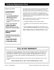
... replacement parts are listed on a decal attached to defect in material or workmanship in this manual to find that: • you need to state. See the front cover of this SEARS WEIGHT SYSTEM EXERCISER, contact the nearest SEARS Service Center throughout the United States and SEARS will repair or replace the WEIGHT SYSTEM EXERCISER, free of the decal. This warranty gives you specific legal rights, and you visit your NordicTrack®...
... replacement parts are listed on a decal attached to defect in material or workmanship in this manual to find that: • you need to state. See the front cover of this SEARS WEIGHT SYSTEM EXERCISER, contact the nearest SEARS Service Center throughout the United States and SEARS will repair or replace the WEIGHT SYSTEM EXERCISER, free of the decal. This warranty gives you specific legal rights, and you visit your NordicTrack®...


