

English Manual
Page 1
... CAUTION Read all precautions and instructions in this manual before using this manual for future reference. ¨ USERÕS MANUAL Visit our website at www.nordictrack.com new products, prizes, fitness tips, and much more! Patent Pending Model No. Write the serial number in the location shown below. As a manufacturer, we...
... CAUTION Read all precautions and instructions in this manual before using this manual for future reference. ¨ USERÕS MANUAL Visit our website at www.nordictrack.com new products, prizes, fitness tips, and much more! Patent Pending Model No. Write the serial number in the location shown below. As a manufacturer, we...

English Manual
Page 2
Always wear athletic shoes for home use of this manual. The home gym is especially important for persons over the age of 35 or persons with great force. 3. Cover the floor or carpet beneath the home gym for personal injury or property damage sustained by or through the use only. Inspect and tighten all users of the home gym are adequately informed of serious injury, read the following important precautions before using the home gym. 10. This is intended for foot protection when exercising. 11. Use the home gym only on all of 12 and pets away from the home gym at...
Always wear athletic shoes for home use of this manual. The home gym is especially important for persons over the age of 35 or persons with great force. 3. Cover the floor or carpet beneath the home gym for personal injury or property damage sustained by or through the use only. Inspect and tighten all users of the home gym are adequately informed of serious injury, read the following important precautions before using the home gym. 10. This is intended for foot protection when exercising. 11. Use the home gym only on all of 12 and pets away from the home gym at...

English Manual
Page 3
...achieve the results you , please note the product model number and serial number before Before reading further, please familiarize yourself using the Nordictrack GRT470. Leg Lever Foam Pads Row Bar Low Pulley Station Foot Plate 3 with the parts that are labeled in . Depth: 60 ...read this manual). If you for selecting the innovative and versatile NordicTrack¨ GRT470 home gym. The model number is to develop every major muscle group of this manual carefully before calling. The NordicTrack GRT470 offers a large selection of weight stations designed to tone your body...
...achieve the results you , please note the product model number and serial number before Before reading further, please familiarize yourself using the Nordictrack GRT470. Leg Lever Foam Pads Row Bar Low Pulley Station Foot Plate 3 with the parts that are labeled in . Depth: 60 ...read this manual). If you for selecting the innovative and versatile NordicTrack¨ GRT470 home gym. The model number is to develop every major muscle group of this manual carefully before calling. The NordicTrack GRT470 offers a large selection of weight stations designed to tone your body...
English Manual
Page 4
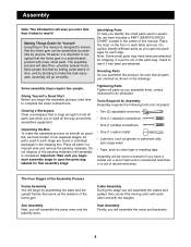
Most people find that by setting aside plenty of time, and by deciding to quickly identify different parts as you open the packages for each stage are oriented as shown in the drawings. Place the chart on the floor or work table and use it to make the assembly process as smooth as clear tape or masking tape Assembly will be more time than it takes to ensure that the home gym can be assembled successfully by anyone. Giving Yourself a Good Start Before you begin the assembly process, take timeÑpossibly several hours. Unpacking the Box To make the task enjoyable, assembly will ...
Most people find that by setting aside plenty of time, and by deciding to quickly identify different parts as you open the packages for each stage are oriented as shown in the drawings. Place the chart on the floor or work table and use it to make the assembly process as smooth as clear tape or masking tape Assembly will be more time than it takes to ensure that the home gym can be assembled successfully by anyone. Giving Yourself a Good Start Before you begin the assembly process, take timeÑpossibly several hours. Unpacking the Box To make the task enjoyable, assembly will ...

English Manual
Page 5
Before beginning, make sure that you have read and understood the information on the floor. Press a 2Ó Square Inner Cap (28) into each Bolt. Place the Butterfly Base flat on page 4. See drawing 1b. See drawing 2a. Note: If the Bolts fall out, secure them by putting a small piece of tape over the head of the Butterfly Base (4). Insert two 5/16Ó x 2 1/2Ó Carriage Bolts (92) up through the indicated holes in the Press Base (6). 5 6 28 28 See drawing 2b. Place the Weight Base flat on the floor. Press a 2Ó Square Inner Cap (28) 2a into each end...
Before beginning, make sure that you have read and understood the information on the floor. Press a 2Ó Square Inner Cap (28) into each Bolt. Place the Butterfly Base flat on page 4. See drawing 1b. See drawing 2a. Note: If the Bolts fall out, secure them by putting a small piece of tape over the head of the Butterfly Base (4). Insert two 5/16Ó x 2 1/2Ó Carriage Bolts (92) up through the indicated holes in the Press Base (6). 5 6 28 28 See drawing 2b. Place the Weight Base flat on the floor. Press a 2Ó Square Inner Cap (28) 2a into each end...

English Manual
Page 6
Hand tighten two 5/16Ó Nylon Locknuts (64) onto the Bolts. 9 5 64 92 6 Place the bracket on the lower end of the Butterfly Upright (1) over the indicated 5/16Ó x 2 1/2Ó Carriage Bolts (92) in the Weight Base (5). Hand tighten two 5/16Ó Nylon Locknuts (64) onto the Bolts. 28 Thread an Adjustment Handle (85) into the indicated 1 hole in the Butterfly Base (4). Press three 2Ó Square Inner Caps (28) into the Weight 4 Upright (9). 28 Place the bracket on the lower end of the Weight Upright (9) over the indicated 5/16Ó x 2 1/2Ó ...
Hand tighten two 5/16Ó Nylon Locknuts (64) onto the Bolts. 9 5 64 92 6 Place the bracket on the lower end of the Butterfly Upright (1) over the indicated 5/16Ó x 2 1/2Ó Carriage Bolts (92) in the Weight Base (5). Hand tighten two 5/16Ó Nylon Locknuts (64) onto the Bolts. 28 Thread an Adjustment Handle (85) into the indicated 1 hole in the Butterfly Base (4). Press three 2Ó Square Inner Caps (28) into the Weight 4 Upright (9). 28 Place the bracket on the lower end of the Weight Upright (9) over the indicated 5/16Ó x 2 1/2Ó ...

English Manual
Page 7
Place the bracket on the Press Upright. Do not tighten the Nylon 89 Locknuts yet. 36 92 1 64 64 64 33 7. Thread an Adjustment Handle (85) into the welded tube on the lower end of the Press Upright (2) onto the indicated 5/16Ó x 2 1/2Ó Carriage Bolts (92) and secure it with two 5/16Ó x 2 3/4Ó Bolts (89), two 5/16Ó Washers (36), and two 5/16Ó 36 Nylon Locknuts (64). With a second person holding the Right Support 6 Frame (33) in position, attach the Left Support Frame to the Butterfly Upright (1) with two 5/16Ó Nylon Locknuts (64). Press...
Place the bracket on the Press Upright. Do not tighten the Nylon 89 Locknuts yet. 36 92 1 64 64 64 33 7. Thread an Adjustment Handle (85) into the welded tube on the lower end of the Press Upright (2) onto the indicated 5/16Ó x 2 1/2Ó Carriage Bolts (92) and secure it with two 5/16Ó x 2 3/4Ó Bolts (89), two 5/16Ó Washers (36), and two 5/16Ó 36 Nylon Locknuts (64). With a second person holding the Right Support 6 Frame (33) in position, attach the Left Support Frame to the Butterfly Upright (1) with two 5/16Ó Nylon Locknuts (64). Press...

English Manual
Page 8
Hand tighten two 5/16Ó Nylon Locknuts (64) onto the Bolts. Attach the Butterfly Seat Frame (14) to the Butterfly Front Leg (3) with two 5/16Ó x 2 3/4Ó Bolts (89), two 5/16Ó Washers (36), and two 5/16Ó Nylon Locknuts (64). Thread an Adjustment Handle (85) into the indicated hole in the Butterfly Base (4). Attach the Butterfly Seat Frame (14) to the Butterfly Upright (1) with two 5/16Ó x 2 3/4Ó Bolts (89) and two 5/16Ó Nylon Locknuts (64). Tighten all Nylon Locknuts used in steps 9 and 10. 8 10 85 1 64 14 66 36 36 64 36 64 3 89 ...
Hand tighten two 5/16Ó Nylon Locknuts (64) onto the Bolts. Attach the Butterfly Seat Frame (14) to the Butterfly Front Leg (3) with two 5/16Ó x 2 3/4Ó Bolts (89), two 5/16Ó Washers (36), and two 5/16Ó Nylon Locknuts (64). Thread an Adjustment Handle (85) into the indicated hole in the Butterfly Base (4). Attach the Butterfly Seat Frame (14) to the Butterfly Upright (1) with two 5/16Ó x 2 3/4Ó Bolts (89) and two 5/16Ó Nylon Locknuts (64). Tighten all Nylon Locknuts used in steps 9 and 10. 8 10 85 1 64 14 66 36 36 64 36 64 3 89 ...

English Manual
Page 9
Make sure that the Weights are turned so the pin grooves are on the Weight Upright (9) with a 3/8Ó x 6 1/2Ó Bolt (55) and a 3/8Ó Nylon Locknut (50). 11 15 16 17 18 Groove Pin Grooves 5 51 94 21 Large Pin Groove 21 51 12. Hand tighten two 5/16Ó Nylon Locknuts (64) onto the Bolts. Press a Weight Tube Bumper (18) into the holes. Attach the Weight Guides (15) to the welded tube on the Weight Base (5). Do not tighten the Nylon Locknuts yet. 20 64 64 92 6 9 Turn the Weights so the large pin grooves point toward the floor. 11. Insert the Weight Guides (...
Make sure that the Weights are turned so the pin grooves are on the Weight Upright (9) with a 3/8Ó x 6 1/2Ó Bolt (55) and a 3/8Ó Nylon Locknut (50). 11 15 16 17 18 Groove Pin Grooves 5 51 94 21 Large Pin Groove 21 51 12. Hand tighten two 5/16Ó Nylon Locknuts (64) onto the Bolts. Press a Weight Tube Bumper (18) into the holes. Attach the Weight Guides (15) to the welded tube on the Weight Base (5). Do not tighten the Nylon Locknuts yet. 20 64 64 92 6 9 Turn the Weights so the large pin grooves point toward the floor. 11. Insert the Weight Guides (...

English Manual
Page 10
Attach the Press Seat Frame (7) to the Press Front Leg (20) with the Bolt and a 3/8Ó Nylon Locknut (50). Attach the Leg Lever (41) to the Press Upright (2) with 38 1 two Retainer Rings (31) and a 1Ó Round Outer Cap (38) in the following the procedure described above. 31 Teeth 29 38 10 Do not tighten the Nylon Locknuts yet. Attach the Press Seat Frame (7) to the Press Front Leg (20) with two 5/16Ó x 2 3/4Ó Bolts (89), two 5/16Ó Washers (36), and two 5/16Ó Nylon Locknuts (64). Do not overtighten the Nylon Locknut; Press a 2Ó Square ...
Attach the Press Seat Frame (7) to the Press Front Leg (20) with the Bolt and a 3/8Ó Nylon Locknut (50). Attach the Leg Lever (41) to the Press Upright (2) with 38 1 two Retainer Rings (31) and a 1Ó Round Outer Cap (38) in the following the procedure described above. 31 Teeth 29 38 10 Do not tighten the Nylon Locknuts yet. Attach the Press Seat Frame (7) to the Press Front Leg (20) with two 5/16Ó x 2 3/4Ó Bolts (89), two 5/16Ó Washers (36), and two 5/16Ó Nylon Locknuts (64). Do not overtighten the Nylon Locknut; Press a 2Ó Square ...

English Manual
Page 11
Do not overtighten the Nylon Locknut; Attach the Butterfly Cable to the welded tube on pages 24 and 25. 19 Important note: Although the following steps are not difficult to the functioning of a Press Arm (77). Press two 1 3/4Ó Square Inner Caps (35) into the lower end 18 of the weight system. the Press Arm 35 must be mounted underneath the welded bracket. 11 77 76 28 84 Welded Bracket 63 11 73 Press a 2Ó Square Inner Cap (28) into the 17 Press Frame (8). Press a 1Ó Inner Cap (76) into the indicated hole in each end. Locate and open the parts bag...
Do not overtighten the Nylon Locknut; Attach the Butterfly Cable to the welded tube on pages 24 and 25. 19 Important note: Although the following steps are not difficult to the functioning of a Press Arm (77). Press two 1 3/4Ó Square Inner Caps (35) into the lower end 18 of the weight system. the Press Arm 35 must be mounted underneath the welded bracket. 11 77 76 28 84 Welded Bracket 63 11 73 Press a 2Ó Square Inner Cap (28) into the 17 Press Frame (8). Press a 1Ó Inner Cap (76) into the indicated hole in each end. Locate and open the parts bag...

English Manual
Page 12
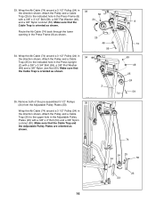
Note: The loop on the back of the Butterfly Upright (1) with a 3/8Ó x 2Ó Bolt (54) and a 3/8Ó Nylon Locknut (50). Welded Bracket 1 32 27 53 50 73 21. Attach the Pulley to the welded bracket (not visible in the Adjustable Pulley Plates (23) with a 3/8Ó x 2 1/2Ó Bolt (53) and a 3/8Ó Nylon Locknut (50). Attach the ÒVÓ-Pulley and a Large Cable Trap (32) to the top hole in the drawing) on the Right Butterfly Arm (10) with a 3/8Ó x 2 1/2Ó Bolt (53) and a 3/8Ó Nylon Locknut (50). Bracket 53 27 32 50 73 23. ...
Note: The loop on the back of the Butterfly Upright (1) with a 3/8Ó x 2Ó Bolt (54) and a 3/8Ó Nylon Locknut (50). Welded Bracket 1 32 27 53 50 73 21. Attach the Pulley to the welded bracket (not visible in the Adjustable Pulley Plates (23) with a 3/8Ó x 2 1/2Ó Bolt (53) and a 3/8Ó Nylon Locknut (50). Attach the ÒVÓ-Pulley and a Large Cable Trap (32) to the top hole in the drawing) on the Right Butterfly Arm (10) with a 3/8Ó x 2 1/2Ó Bolt (53) and a 3/8Ó Nylon Locknut (50). Bracket 53 27 32 50 73 23. ...

English Manual
Page 13
Identify the Weight Cable (72). Thread the 1/2Ó Plain Nut (100) onto the bolt at the end of the Weight Cable into the Weight Tube (17) until all Cables are tight and rest firmly in the Weight Upright (9) with a 3/8Ó x 2 3/4Ó Bolt (46), two 3/8Ó Flat Washers (48), two 5/8Ó x 1/2Ó Spacers (102) and a 3/8Ó Nylon Locknut (50). 50 9 48 102 24 102 Slot 48 46 72 15 13 Place the Long Weight 72 Spacer (96) over a 3 1/2Ó Pulley (24) as shown and then through the slot in the Weight Upright (9). Note: The bolt at the end of the ...
Identify the Weight Cable (72). Thread the 1/2Ó Plain Nut (100) onto the bolt at the end of the Weight Cable into the Weight Tube (17) until all Cables are tight and rest firmly in the Weight Upright (9) with a 3/8Ó x 2 3/4Ó Bolt (46), two 3/8Ó Flat Washers (48), two 5/8Ó x 1/2Ó Spacers (102) and a 3/8Ó Nylon Locknut (50). 50 9 48 102 24 102 Slot 48 46 72 15 13 Place the Long Weight 72 Spacer (96) over a 3 1/2Ó Pulley (24) as shown and then through the slot in the Weight Upright (9). Note: The bolt at the end of the ...

English Manual
Page 14
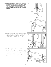
Place the Weight Cable (72) in the direction shown. Wrap the Weight Cable (72) around a 3 1/2Ó Pulley (24) in the groove of a 26 3 1/2Ó Pulley (24) and push the Pulley up into the welded bracket on the Weight Upright (9) with a 3/8Ó x 1 3/4Ó Bolt (57) and a 3/8Ó Nylon Locknut (50). 50 9 24 72 Welded Bracket 57 27. Remove both 3 1/2Ó Pulleys (24) from the pre-assem- 27 bled Pulley Frame (22). Make sure that the Pulley Frame is turned as shown. 50 72 24 57 22 28. Attach the closed loop on the Weight Cable (72) 28 inside the welded bracket ...
Place the Weight Cable (72) in the direction shown. Wrap the Weight Cable (72) around a 3 1/2Ó Pulley (24) in the groove of a 26 3 1/2Ó Pulley (24) and push the Pulley up into the welded bracket on the Weight Upright (9) with a 3/8Ó x 1 3/4Ó Bolt (57) and a 3/8Ó Nylon Locknut (50). 50 9 24 72 Welded Bracket 57 27. Remove both 3 1/2Ó Pulleys (24) from the pre-assem- 27 bled Pulley Frame (22). Make sure that the Pulley Frame is turned as shown. 50 72 24 57 22 28. Attach the closed loop on the Weight Cable (72) 28 inside the welded bracket ...

English Manual
Page 15
Attach the Pulley and a Cable Trap (25) to the indicated hole (the second hole from the end) in the Press Upright (2) with a 3/8Ó x 4Ó Bolt (60), a 3/8Ó Flat Washer (48), and a 3/8Ó Nylon Locknut (50). Attach the ÒVÓ-Pulley and a Large Cable Trap (32) to the indicated hole (make sure you select the upper hole) in the tube on each end. 29 Lat Bar 63 Wrap one end of the Ab Cable (74) around a ÒVÓ-Pulley (27) in the Press Frame (8) as shown. Attach the 74 Pulley to the indicated hole in the direction shown. Make sure that the ...
Attach the Pulley and a Cable Trap (25) to the indicated hole (the second hole from the end) in the Press Upright (2) with a 3/8Ó x 4Ó Bolt (60), a 3/8Ó Flat Washer (48), and a 3/8Ó Nylon Locknut (50). Attach the ÒVÓ-Pulley and a Large Cable Trap (32) to the indicated hole (make sure you select the upper hole) in the tube on each end. 29 Lat Bar 63 Wrap one end of the Ab Cable (74) around a ÒVÓ-Pulley (27) in the Press Frame (8) as shown. Attach the 74 Pulley to the indicated hole in the direction shown. Make sure that the ...
English Manual
Page 16
Route the Ab Cable (74) back through the lower opening in the Press Frame (8) as shown. 2 35. Remove both of the pre-assembled 3 1/2Ó Pulleys 35 (24) from the Adjustable Pulley Plates (23). Attach the Pulley and a Cable 50 Trap (25) to the indicated hole in the Press Frame (8) with a 3/8Ó x 2Ó Bolt (54) and a 3/8Ó Nylon Locknut (50). Make sure that the Cable Trap is oriented as shown. 8 74 63 48 25 24 59 74 74 24 25 54 50 23 23 16 Attach the Pulley and a Cable Trap (25) to the indicated hole in the Press Upright (2) with a 3/8Ó x 3 ...
Route the Ab Cable (74) back through the lower opening in the Press Frame (8) as shown. 2 35. Remove both of the pre-assembled 3 1/2Ó Pulleys 35 (24) from the Adjustable Pulley Plates (23). Attach the Pulley and a Cable 50 Trap (25) to the indicated hole in the Press Frame (8) with a 3/8Ó x 2Ó Bolt (54) and a 3/8Ó Nylon Locknut (50). Make sure that the Cable Trap is oriented as shown. 8 74 63 48 25 24 59 74 74 24 25 54 50 23 23 16 Attach the Pulley and a Cable Trap (25) to the indicated hole in the Press Upright (2) with a 3/8Ó x 3 ...

English Manual
Page 17
Identify the Low Cable (75). Wrap the Low Cable (75) around a 3 1/2Ó Pulley (24) 38 in the Butterfly Upright (1) with a 3/8Ó x 2Ó Bolt (54) and a 3/8Ó Nylon Locknut (50). 37 Welded Bracket 54 75 38. Attach the Pulley and the Pulley Covers to the welded bracket on the Butterfly Base (4). Attach the Pulley and a Cable Trap (25) to the indicated hole in the Press Upright (2) with the closed loop on the Upright. 47 74 24 47 2 48 59 37. Attach the Pulley and a Cable 1 Trap (25) to the indicated hole in the direction shown. Wrap the Low ...
Identify the Low Cable (75). Wrap the Low Cable (75) around a 3 1/2Ó Pulley (24) 38 in the Butterfly Upright (1) with a 3/8Ó x 2Ó Bolt (54) and a 3/8Ó Nylon Locknut (50). 37 Welded Bracket 54 75 38. Attach the Pulley and the Pulley Covers to the welded bracket on the Butterfly Base (4). Attach the Pulley and a Cable Trap (25) to the indicated hole in the Press Upright (2) with the closed loop on the Upright. 47 74 24 47 2 48 59 37. Attach the Pulley and a Cable 1 Trap (25) to the indicated hole in the direction shown. Wrap the Low ...
English Manual
Page 18
39. Wrap the Low Cable (75) around a 3 1/2Ó Pulley (24) 39 in the direction shown. Attach the Pulley to the welded bracket on the Weight Base (5) with a 3/8Ó x 1 3/4Ó Bolt (57) and a 3/8Ó Nylon Locknut (50). Attach the Pulley and a Cable Trap (25) to the lower hole in the direction shown. Welded Bracket 75 57 24 4 50 41. Make sure the Cable Trap is not shown. 41 Wrap the Low Cable (75) around a 3 1/2Ó Pulley (24) 40 in the direction shown. Note: For clarity, the weight stack is oriented as shown. 54 23 50 25 24 75 40. Wrap the ...
39. Wrap the Low Cable (75) around a 3 1/2Ó Pulley (24) 39 in the direction shown. Attach the Pulley to the welded bracket on the Weight Base (5) with a 3/8Ó x 1 3/4Ó Bolt (57) and a 3/8Ó Nylon Locknut (50). Attach the Pulley and a Cable Trap (25) to the lower hole in the direction shown. Welded Bracket 75 57 24 4 50 41. Make sure the Cable Trap is not shown. 41 Wrap the Low Cable (75) around a 3 1/2Ó Pulley (24) 40 in the direction shown. Note: For clarity, the weight stack is oriented as shown. 54 23 50 25 24 75 40. Wrap the ...

English Manual
Page 19
Wrap the Low Cable (75) around a 3 1/2Ó Pulley (24) 44 in the direction shown. Attach the Pulley to the lower half of the Pulley Frame (22) with a 3/8Ó x 1 3/4Ó Bolt (57) and a 3/8Ó Nylon Locknut (50). Make sure the Cable Trap is oriented as shown. 50 23 50 25 54 24 75 19 Attach the Pulley to the welded bracket on the Press Base (6) with a 3/8Ó x 1 3/4Ó Bolt (57) and a 3/8Ó Nylon Locknut (50). 22 57 50 24 75 43. Welded Bracket 75 75 Welded Bracket 6 24 57 45. 42. Attach the Pulley and a Cable Trap (25) to the lower hole in ...
Wrap the Low Cable (75) around a 3 1/2Ó Pulley (24) 44 in the direction shown. Attach the Pulley to the lower half of the Pulley Frame (22) with a 3/8Ó x 1 3/4Ó Bolt (57) and a 3/8Ó Nylon Locknut (50). Make sure the Cable Trap is oriented as shown. 50 23 50 25 54 24 75 19 Attach the Pulley to the welded bracket on the Press Base (6) with a 3/8Ó x 1 3/4Ó Bolt (57) and a 3/8Ó Nylon Locknut (50). 22 57 50 24 75 43. Welded Bracket 75 75 Welded Bracket 6 24 57 45. 42. Attach the Pulley and a Cable Trap (25) to the lower hole in ...
English Manual
Page 20
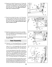
Wrap the Low Cable (75) around a 3 1/2Ó Pulley (24) 46 in a Seat Plate (65). Make sure that the 75 2 Cable Trap is oriented as shown. 63 24 25 20 59 75 48 59 48. Insert a 1/4Ó x 1 1/2Ó Carriage Bolt (101) into the center hole in the direction shown. Release the Adjustment Handle and let the tip snap into the indicated hole in the vertical tube are on the Seat Adjustment Frame (90) into one of the Seats (13) with a 3/8Ó x 3 3/4Ó Bolt (59), a 3/8Ó Flat Washer (48), and a 3/8Ó Nylon Jam nut (63). Route the Low Cable (75) under a 3 ...
Wrap the Low Cable (75) around a 3 1/2Ó Pulley (24) 46 in a Seat Plate (65). Make sure that the 75 2 Cable Trap is oriented as shown. 63 24 25 20 59 75 48 59 48. Insert a 1/4Ó x 1 1/2Ó Carriage Bolt (101) into the center hole in the direction shown. Release the Adjustment Handle and let the tip snap into the indicated hole in the vertical tube are on the Seat Adjustment Frame (90) into one of the Seats (13) with a 3/8Ó x 3 3/4Ó Bolt (59), a 3/8Ó Flat Washer (48), and a 3/8Ó Nylon Jam nut (63). Route the Low Cable (75) under a 3 ...