
English Manual
Page 3
... protection while exercising. 3. Reduce your back. 15. do not wear loose clothes that all users of the elliptical are adequately informed of all times. 12. Various factors may result in serious injury or death. Keep the elliptical indoors, away from the elliptical at least 3 ft. (0.9 m) of clearance in the front and rear of the...
... protection while exercising. 3. Reduce your back. 15. do not wear loose clothes that all users of the elliptical are adequately informed of all times. 12. Various factors may result in serious injury or death. Keep the elliptical indoors, away from the elliptical at least 3 ft. (0.9 m) of clearance in the front and rear of the...

English Manual
Page 8
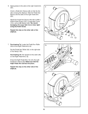
... Pad (151) on the Right Pedal Pad. Then, set the Right Pedal (14) on the Right Pedal Arm (12). Tip: Avoid damaging the Wire Harness (60). Next, tighten two M6 x 50mm Patch Screws (62) with "Right...two Wave Washers (118). Identify the Right Pedal (14), the Right Pedal Pad (151), and the Right Pedal Arm (12) 5 assembly, which are marked with two M6 Washers (112) into each side of the Upright Axle (48) at the...an M8 x 16mm Patch Screw (102) and an M8 Washer (95) into the Right Pedal Arm (12) and the Right Pedal (14). Attach the Right Pedal (14) to the Left Pedal Arm (not shown) assembly...
... Pad (151) on the Right Pedal Pad. Then, set the Right Pedal (14) on the Right Pedal Arm (12). Tip: Avoid damaging the Wire Harness (60). Next, tighten two M6 x 50mm Patch Screws (62) with "Right...two Wave Washers (118). Identify the Right Pedal (14), the Right Pedal Pad (151), and the Right Pedal Arm (12) 5 assembly, which are marked with two M6 Washers (112) into each side of the Upright Axle (48) at the...an M8 x 16mm Patch Screw (102) and an M8 Washer (95) into the Right Pedal Arm (12) and the Right Pedal (14). Attach the Right Pedal (14) to the Left Pedal Arm (not shown) assembly...
English Manual
Page 9
... drawing 7a. Locate the Pedal Arm Roller (32) on the Right Pedal Arm (12). 7a Set the Pedal Arm Roller (32) on the other side of the elliptical. 7b Grease 39 Flat Side 46 95 113 121 32 12 130 12 50 46 9 See drawing 7b. Pull upward on the Latch (50) on the... Arm Sleeve (46) so that the Right Pedal Arm latches into place. Repeat this step on the right side of the elliptical. 7. Make sure that the flat side is facing the elliptical. Tip: Avoid damaging the Large Axle Cover when tightening the Patch Screw. Apply grease to the axle on the other...
... drawing 7a. Locate the Pedal Arm Roller (32) on the Right Pedal Arm (12). 7a Set the Pedal Arm Roller (32) on the other side of the elliptical. 7b Grease 39 Flat Side 46 95 113 121 32 12 130 12 50 46 9 See drawing 7b. Pull upward on the Latch (50) on the... Arm Sleeve (46) so that the Right Pedal Arm latches into place. Repeat this step on the right side of the elliptical. 7. Make sure that the flat side is facing the elliptical. Tip: Avoid damaging the Large Axle Cover when tightening the Patch Screw. Apply grease to the axle on the other...

English Manual
Page 12
... shown. 13 Attach the Rear Upright Cover (25) to start the Screws into the upper end of step 14. 12 33 13. Avoid pinching the wires Upper Holes 105 60 156 5 156 25 5 12 You will tighten the Screws at the end of the Console (33). Do not tighten the M4 x 19mm...
... shown. 13 Attach the Rear Upright Cover (25) to start the Screws into the upper end of step 14. 12 33 13. Avoid pinching the wires Upper Holes 105 60 156 5 156 25 5 12 You will tighten the Screws at the end of the Console (33). Do not tighten the M4 x 19mm...

English Manual
Page 13
...15 Attach the Front Upright Cover (24) around the Upright (5) by pressing the tabs on page 12. Make sure that all parts of the Console (33). 15. Note: An extra grease packet ...the floor or carpet from damage, place a mat under the elliptical. 13 Tighten the M4 x 19mm Screws (156) in the upper end of the elliptical are properly tightened. 14. Attach the lower end of the ...Console (33) to the Upright (5) with two M4 x 19mm Screws (156). 14 See step 12 on the Front Upright Cover ...
...15 Attach the Front Upright Cover (24) around the Upright (5) by pressing the tabs on page 12. Make sure that all parts of the Console (33). 15. Note: An extra grease packet ...the floor or carpet from damage, place a mat under the elliptical. 13 Tighten the M4 x 19mm Screws (156) in the upper end of the elliptical are properly tightened. 14. Attach the lower end of the ...Console (33) to the Upright (5) with two M4 x 19mm Screws (156). 14 See step 12 on the Front Upright Cover ...

English Manual
Page 27
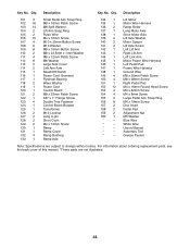
... 1 82 1 83 1 84 1 85 1 86 8 87 2 88 1 89 4 90 1 91 1 92 1 93 1 94 2 95 10 96 1 97 1 98 2 99 1 100 4 Model No. Qty. 1 1 2 1 3 1 4 1 5 1 6 1 7 1 8 1 9 1 10 1 11 1 12 1 13 1 14 1 15 1 16 2 17 2 18 1 19 1 20 1 21 1 22 1 23 2 24 1 25 1 26 1 27 1 28 2 29 18 30 2 31 4 32 2 33 1 34 2 35 2 36...
... 1 82 1 83 1 84 1 85 1 86 8 87 2 88 1 89 4 90 1 91 1 92 1 93 1 94 2 95 10 96 1 97 1 98 2 99 1 100 4 Model No. Qty. 1 1 2 1 3 1 4 1 5 1 6 1 7 1 8 1 9 1 10 1 11 1 12 1 13 1 14 1 15 1 16 2 17 2 18 1 19 1 20 1 21 1 22 1 23 2 24 1 25 1 26 1 27 1 28 2 29 18 30 2 31 4 32 2 33 1 34 2 35 2 36...
English Manual
Page 28
... Ramp Cover Ramp Bushing Ramp Axle 134 1 135 1 136 2 137 1 138 1 139 2 140 2 141 2 142 1 143 1 144 1 145 1 146 1 147 1 148 1 149 4 150 4 151 1 152 12 153 4 154 4 155 2 156 8 157 2 158 2 159 2 160 1 * - * - * - * - * -
... Ramp Cover Ramp Bushing Ramp Axle 134 1 135 1 136 2 137 1 138 1 139 2 140 2 141 2 142 1 143 1 144 1 145 1 146 1 147 1 148 1 149 4 150 4 151 1 152 12 153 4 154 4 155 2 156 8 157 2 158 2 159 2 160 1 * - * - * - * - * -

English Manual
Page 29
29 35 106 9 102 103 149 109 56 95 54 54 102 95 54 7 54 54 144 15 155 146 54 33 34 48 26 25 54 114 95 56 149 28 30 158 13 31 31 112 112 154 53 62 121 113 62 111 50 128 95 58 51 46 30 52 47 49 127 31 106 32 101 151 158 12 31 111 154 106 102 103 11 102 103 118 57 14 101 32 112 47 111 112 62 62 24 156 35 156 156 57 118 5 54 27 10 34 103 102 106 54 95 102 106 8 103 149 56 95 114 54 28 6 103 102 105 54 54 95 56 149 59 43 155 54 46 50 51 58 95 54 113 95 56 109 49 121 53 128 52 127 106 Model No. NTEL07910.2 R0611A EXPLODED DRAWING A
29 35 106 9 102 103 149 109 56 95 54 54 102 95 54 7 54 54 144 15 155 146 54 33 34 48 26 25 54 114 95 56 149 28 30 158 13 31 31 112 112 154 53 62 121 113 62 111 50 128 95 58 51 46 30 52 47 49 127 31 106 32 101 151 158 12 31 111 154 106 102 103 11 102 103 118 57 14 101 32 112 47 111 112 62 62 24 156 35 156 156 57 118 5 54 27 10 34 103 102 106 54 95 102 106 8 103 149 56 95 114 54 28 6 103 102 105 54 54 95 56 149 59 43 155 54 46 50 51 58 95 54 113 95 56 109 49 121 53 128 52 127 106 Model No. NTEL07910.2 R0611A EXPLODED DRAWING A

