
English Manual
Page 2
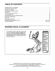
TABLE OF CONTENTS WARNING DECAL PLACEMENT 2 IMPORTANT PRECAUTIONS 3 BEFORE YOU BEGIN 7 PART IDENTIFICATION CHART 8 ASSEMBLY 9 HOW TO USE THE ELLIPTICAL 18 FCC INFORMATION 34 MAINTENANCE AND TROUBLESHOOTING 35 EXERCISE GUIDELINES 37 PART LIST 39 EXPLODED DRAWING 41 ORDERING REPLACEMENT ...the location shown. Note: The decal(s) may not be shown at actual size. IFIT is a registered trademark of ICON Health & Fitness, Inc NORDICTRACK is a trademark of Google Inc. The BLUETOOTH® word mark and logos are used under license. and are registered trademarks of ICON Health &...
TABLE OF CONTENTS WARNING DECAL PLACEMENT 2 IMPORTANT PRECAUTIONS 3 BEFORE YOU BEGIN 7 PART IDENTIFICATION CHART 8 ASSEMBLY 9 HOW TO USE THE ELLIPTICAL 18 FCC INFORMATION 34 MAINTENANCE AND TROUBLESHOOTING 35 EXERCISE GUIDELINES 37 PART LIST 39 EXPLODED DRAWING 41 ORDERING REPLACEMENT ...the location shown. Note: The decal(s) may not be shown at actual size. IFIT is a registered trademark of ICON Health & Fitness, Inc NORDICTRACK is a trademark of Google Inc. The BLUETOOTH® word mark and logos are used under license. and are registered trademarks of ICON Health &...

English Manual
Page 8
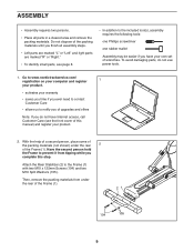
... number in the hardware kit, check to identify the small parts needed for assembly. PART IDENTIFICATION CHART Use the drawings below each drawing is the key number of the part, from the PART LIST near the end of this ...
... number in the hardware kit, check to identify the small parts needed for assembly. PART IDENTIFICATION CHART Use the drawings below each drawing is the key number of the part, from the PART LIST near the end of this ...
English Manual
Page 9
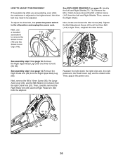
...8. • In addition to the Frame (1) with two M10 x 122mm Screws (104) and two M10 Split Washers (105). ASSEMBLY • Assembly requires two persons. • Place all assembly steps. • Left parts are marked "L" or "Left" and right parts are marked "R" or "Right." • To ...see the front cover of the Frame (1). 21 104 105 9 Attach the Rear Stabilizer (2) to the included tool(s), assembly requires the following tools: one Phillips screwdriver one rubber mallet Assembly may be easier if you complete this manual) and register your own set of the Frame (1).
...8. • In addition to the Frame (1) with two M10 x 122mm Screws (104) and two M10 Split Washers (105). ASSEMBLY • Assembly requires two persons. • Place all assembly steps. • Left parts are marked "L" or "Left" and right parts are marked "R" or "Right." • To ...see the front cover of the Frame (1). 21 104 105 9 Attach the Rear Stabilizer (2) to the included tool(s), assembly requires the following tools: one Phillips screwdriver one rubber mallet Assembly may be easier if you complete this manual) and register your own set of the Frame (1).
English Manual
Page 36
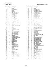
...slip while you are pedaling, even while the resistance is tight. Next, locate and loosen the Idler Screw (89). Then, remove the Right Shield. See assembly step 12 on page 16. Next, use a standard screwdriver to the off position and unplug the power cord. Remove the Right Pedal Arm (58) ...from the elliptical. 89 91 Reattach the right shield, the right roller arm, the right pedal arm, the shield cover cap, and the shield cover. Tighten the Belt...
...slip while you are pedaling, even while the resistance is tight. Next, locate and loosen the Idler Screw (89). Then, remove the Right Shield. See assembly step 12 on page 16. Next, use a standard screwdriver to the off position and unplug the power cord. Remove the Right Pedal Arm (58) ...from the elliptical. 89 91 Reattach the right shield, the right roller arm, the right pedal arm, the shield cover cap, and the shield cover. Tighten the Belt...
English Manual
Page 39
...69 1 70 1 71 2 72 1 73 1 74 1 75 1 76 1 77 4 78 2 79 1 80 1 81 1 82 10 83 1 84 3 85 2 86 2 87 1 88 1 89 1 90 2 91 1 92 2 93 4 94 2 95 8 96 4 97 10 98 2 99 4 100 4 Description Roller Pedal Arm Cap Large Axle Cover 16mm Wave Washer Small Axle Cover Roller... Arm Bushing Arm Bearing Right Pedal Arm Right Roller Arm Right Upper Body Leg Right Upper Body Arm Grip Sensor Assembly/Wire Pedal Arm Axle Right ...
...69 1 70 1 71 2 72 1 73 1 74 1 75 1 76 1 77 4 78 2 79 1 80 1 81 1 82 10 83 1 84 3 85 2 86 2 87 1 88 1 89 1 90 2 91 1 92 2 93 4 94 2 95 8 96 4 97 10 98 2 99 4 100 4 Description Roller Pedal Arm Cap Large Axle Cover 16mm Wave Washer Small Axle Cover Roller... Arm Bushing Arm Bearing Right Pedal Arm Right Roller Arm Right Upper Body Leg Right Upper Body Arm Grip Sensor Assembly/Wire Pedal Arm Axle Right ...
English Manual
Page 40
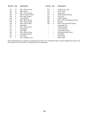
Description 101 37 102 6 103 10 104 4 105 8 106 3 107 1 108 2 109 2 110 1 111 4 112 1 113 1 114 4 115 1 116 2 117 1 M4 x 16mm Screw M8 Locknut M6 x 12mm Screw M10 x 122mm Screw .... Qty. Shield Cover Cap Power Cord Ramp Axle Small Frame Bushing Clevis Pin Plastic Spacer M4 x 19mm Self-tapping Screw Bumper M8 x 14mm Shoulder Screw Assembly Tool Grease Packet User's Manual Incline Motor Wire Resistance Motor Wire Blue Wire Green Wire White Wire Note: Specifications are not illustrated. 40 Qty. Key...
Description 101 37 102 6 103 10 104 4 105 8 106 3 107 1 108 2 109 2 110 1 111 4 112 1 113 1 114 4 115 1 116 2 117 1 M4 x 16mm Screw M8 Locknut M6 x 12mm Screw M10 x 122mm Screw .... Qty. Shield Cover Cap Power Cord Ramp Axle Small Frame Bushing Clevis Pin Plastic Spacer M4 x 19mm Self-tapping Screw Bumper M8 x 14mm Shoulder Screw Assembly Tool Grease Packet User's Manual Incline Motor Wire Resistance Motor Wire Blue Wire Green Wire White Wire Note: Specifications are not illustrated. 40 Qty. Key...


