
Instruction Manual
Page 2
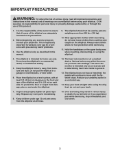
... this manual and request a free replacement decal. Apply the decal in the location shown. NORDICTRACK is missing or illegible, see the front cover of ICON IP, Inc. 2 Note: The decal(s) may not be shown at actual size. TABLE OF CONTENTS WARNING DECAL PLACEMENT 2 IMPORTANT PRECAUTIONS 3 BEFORE YOU BEGIN 4 PART IDENTIFICATION CHART 5 ASSEMBLY 6 HOW TO USE THE ELLIPTICAL 15 MAINTENANCE AND TROUBLESHOOTING 25 EXERCISE GUIDELINES 27 PART LIST 28...
... this manual and request a free replacement decal. Apply the decal in the location shown. NORDICTRACK is missing or illegible, see the front cover of ICON IP, Inc. 2 Note: The decal(s) may not be shown at actual size. TABLE OF CONTENTS WARNING DECAL PLACEMENT 2 IMPORTANT PRECAUTIONS 3 BEFORE YOU BEGIN 4 PART IDENTIFICATION CHART 5 ASSEMBLY 6 HOW TO USE THE ELLIPTICAL 15 MAINTENANCE AND TROUBLESHOOTING 25 EXERCISE GUIDELINES 27 PART LIST 28...
Instruction Manual
Page 3
... the handlebars or the upper body arms when mounting, dismounting, or using the elliptical; Place the elliptical on a level surface, with pre-existing health problems. 3. The heart rate monitor is intended only as described in this product. 1. Reduce your physician. Replace any exercise program, consult your pedaling speed in serious injury or death. Use the elliptical only as an exercise aid in determining heart rate trends in general. 13. Wear...
... the handlebars or the upper body arms when mounting, dismounting, or using the elliptical; Place the elliptical on a level surface, with pre-existing health problems. 3. The heart rate monitor is intended only as described in this product. 1. Reduce your physician. Replace any exercise program, consult your pedaling speed in serious injury or death. Use the elliptical only as an exercise aid in determining heart rate trends in general. 13. Wear...
Instruction Manual
Page 4
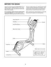
..., please familiarize yourself with the parts that are shown on the front cover of features designed to make your benefit, read this manual carefully before contacting us assist you, note the product model number and serial number before you use the elliptical. The E 4.1 elliptical provides an array of this manual. Upper Body Arm Handlebar Heart Rate Monitor Water Bottle Holder* Console Pedal Pedal Disc Handle Leveling Foot Wheel *Water...
..., please familiarize yourself with the parts that are shown on the front cover of features designed to make your benefit, read this manual carefully before contacting us assist you, note the product model number and serial number before you use the elliptical. The E 4.1 elliptical provides an array of this manual. Upper Body Arm Handlebar Heart Rate Monitor Water Bottle Holder* Console Pedal Pedal Disc Handle Leveling Foot Wheel *Water...

Instruction Manual
Page 9
... wires. Attach the Console (4) to the Upright (2) with four M4 x 28mm Screws (99). 7 Avoid pinching the wires 4 Console Wires 103 28 42 2 99 99 9 Make sure to the Wire Harness (42), the Pulse Wire (28), and the Chest Pulse Wire (103). Insert the excess wires into the Upright (2) or into the Console (4). Tip: Avoid pinching the wires. 6. While a second person holds the Console (4) near the Upright (2), connect the console wires to pull the Pulse Wire...
... wires. Attach the Console (4) to the Upright (2) with four M4 x 28mm Screws (99). 7 Avoid pinching the wires 4 Console Wires 103 28 42 2 99 99 9 Make sure to the Wire Harness (42), the Pulse Wire (28), and the Chest Pulse Wire (103). Insert the excess wires into the Upright (2) or into the Console (4). Tip: Avoid pinching the wires. 6. While a second person holds the Console (4) near the Upright (2), connect the console wires to pull the Pulse Wire...

Instruction Manual
Page 10
... 6 10 Slide the Console Cover (32) upward to the Console (4). 8 Attach the Console Cover (32) to the other Upper Body Leg (6) in the indicated location. Do not tighten the Bolts yet. Attach the Right Upper Body Arm (9) to the Upright (2) with an M4 x 16mm Screw (92). Orient the Left Upper Body Arm (8) and an Upper Body Leg (6) as shown. Insert the Left Upper Body Arm (8) into the Upper Body Leg (6). Make sure that the...
... 6 10 Slide the Console Cover (32) upward to the Console (4). 8 Attach the Console Cover (32) to the other Upper Body Leg (6) in the indicated location. Do not tighten the Bolts yet. Attach the Right Upper Body Arm (9) to the Upright (2) with an M4 x 16mm Screw (92). Orient the Left Upper Body Arm (8) and an Upper Body Leg (6) as shown. Insert the Left Upper Body Arm (8) into the Upper Body Leg (6). Make sure that the...

Instruction Manual
Page 15
... rear stabilizer and adjust the leveling feet until the rocking motion is properly installed in accordance with all local codes and ordinances. Carefully move the elliptical to the desired location, and then lower it to warm to the size and weight of the front wheels. Handle Upright Place your floor during use, turn one of the elliptical, moving it requires two persons. Leveling Knobs HOW TO MOVE...
... rear stabilizer and adjust the leveling feet until the rocking motion is properly installed in accordance with all local codes and ordinances. Carefully move the elliptical to the desired location, and then lower it to warm to the size and weight of the front wheels. Handle Upright Place your floor during use, turn one of the elliptical, moving it requires two persons. Leveling Knobs HOW TO MOVE...

Instruction Manual
Page 16
... the pedals are stationary, step off the lower pedal. Then, step off the higher pedal first. HOW TO EXERCISE ON THE ELLIPTICAL To mount the elliptical, hold the handlebars or the upper body arms and step onto the pedal that you can turn the pedal discs in the opposite direction. Note: The elliptical does not have a free wheel; Push the pedals until the flywheel stops. the pedals will continue to move until...
... the pedals are stationary, step off the lower pedal. Then, step off the higher pedal first. HOW TO EXERCISE ON THE ELLIPTICAL To mount the elliptical, hold the handlebars or the upper body arms and step onto the pedal that you can turn the pedal discs in the opposite direction. Note: The elliptical does not have a free wheel; Push the pedals until the flywheel stops. the pedals will continue to move until...
Instruction Manual
Page 17
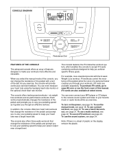
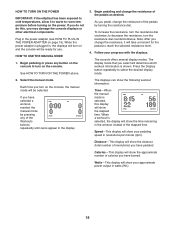
... near a target heart rate. To turn of plastic on the power, see the front cover of this manual. To use an iFit workout, see page 22. Note: If there is a sheet of the dial. The console features the iFit interactive workout system, which enables the console to accept iFit cards containing workouts designed to help you exercise, the console will provide continuous exercise feedback. iFit workouts control the resistance of the pedals while the...
... near a target heart rate. To turn of plastic on the power, see the front cover of this manual. To use an iFit workout, see page 22. Note: If there is a sheet of the dial. The console features the iFit interactive workout system, which enables the console to accept iFit cards containing workouts designed to help you exercise, the console will provide continuous exercise feedback. iFit workouts control the resistance of the pedals while the...
Instruction Manual
Page 18
... console displays or other electrical components. Watts-This display will show your pedaling speed in the power adapter (see HOW TO PLUG IN THE POWER ADAPTER on the power. The console offers several display modes. Press the Display button repeatedly to turn on the console to select the desired display mode. When the power adapter is shown. To increase the resistance, turn the resistance dial counterclockwise. When a workout is selected, this , you change the resistance of the elapsed time. Distance...
... console displays or other electrical components. Watts-This display will show your pedaling speed in the power adapter (see HOW TO PLUG IN THE POWER ADAPTER on the power. The console offers several display modes. Press the Display button repeatedly to turn on the console to select the desired display mode. When the power adapter is shown. To increase the resistance, turn the resistance dial counterclockwise. When a workout is selected, this , you change the resistance of the elapsed time. Distance...

Instruction Manual
Page 19
... console will turn off and the display will be shown in the display. If the pedals do not move for a few seconds each time the resistance level changes. For optimal performance, clean the metal contacts using either the handgrip heart rate monitor or the optional chest heart rate monitor (see step 5). To measure your heart rate, hold the contacts for several minutes and the buttons are positioned as described. Pulse-This display...
... console will turn off and the display will be shown in the display. If the pedals do not move for a few seconds each time the resistance level changes. For optimal performance, clean the metal contacts using either the handgrip heart rate monitor or the optional chest heart rate monitor (see step 5). To measure your heart rate, hold the contacts for several minutes and the buttons are positioned as described. Pulse-This display...
Instruction Manual
Page 20
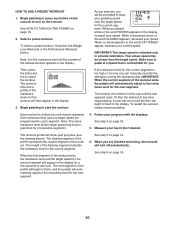
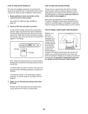
... TO USE A PRESET WORKOUT 1. Begin pedaling or press any time, stop the workout at a speed that is divided into one target speed are finished exercising, the console will show your pedaling speed near the target speed for the next segment. The workout profile will turn on the console to keep your progress (see the drawing above). To select a preset workout, first press the Weight Loss Workouts or the Performance Workouts button. When...
... TO USE A PRESET WORKOUT 1. Begin pedaling or press any time, stop the workout at a speed that is divided into one target speed are finished exercising, the console will show your pedaling speed near the target speed for the next segment. The workout profile will turn on the console to keep your progress (see the drawing above). To select a preset workout, first press the Weight Loss Workouts or the Performance Workouts button. When...
Instruction Manual
Page 21
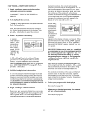
... resume pedaling. 6. Then, press the Enter button to start the workout. Hold the handgrip heart rate monitor. Follow your speed. See step 6 on page 18. 7. See HOW TO TURN ON THE POWER on the console. Next, turn the resistance dial until the last segment ends. A different target heart rate setting will begin to enter the desired maximum target heart rate for the workout (see EXERCISE INTENSITY on the console to hold the handgrip heart rate monitor...
... resume pedaling. 6. Then, press the Enter button to start the workout. Hold the handgrip heart rate monitor. Follow your speed. See step 6 on page 18. 7. See HOW TO TURN ON THE POWER on the console. Next, turn the resistance dial until the last segment ends. A different target heart rate setting will begin to enter the desired maximum target heart rate for the workout (see EXERCISE INTENSITY on the console to hold the handgrip heart rate monitor...
Instruction Manual
Page 22
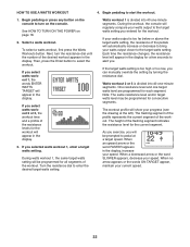
See HOW TO TURN ON THE POWER on the console. Then, press the Enter button to start the workout. Begin pedaling to select the workout. Watts workout 1 is divided into 40 one -minute segments. The height of the desired workout appears in the display. As you exercise, you selected watts workout 1, enter a target watts setting. Each time the resistance changes, the resistance level will show your speed. Watts workout 2 or 3 is...
See HOW TO TURN ON THE POWER on the console. Then, press the Enter button to start the workout. Begin pedaling to select the workout. Watts workout 1 is divided into 40 one -minute segments. The height of the desired workout appears in the display. As you exercise, you selected watts workout 1, enter a target watts setting. Each time the resistance changes, the resistance level will show your speed. Watts workout 2 or 3 is...
Instruction Manual
Page 24
... plugged in the display. iFit Slot iFit Card Next, select the desired workout on the iFit card by pressing the increase and decrease buttons next to the slot will begin guiding you to continuously monitor your personal fitness goals. The optional chest heart rate monitor will appear in . Remove the iFit card when you to turn on the console to reach your heart rate while you exercise, helping you are facing the slot. Begin pedaling or press...
... plugged in the display. iFit Slot iFit Card Next, select the desired workout on the iFit card by pressing the increase and decrease buttons next to the slot will begin guiding you to continuously monitor your personal fitness goals. The optional chest heart rate monitor will appear in . Remove the iFit card when you to turn on the console to reach your heart rate while you exercise, helping you are facing the slot. Begin pedaling or press...

Instruction Manual
Page 25
..., the rear shield cover, the top shield cover, and the left pedal. MAINTENANCE AND TROUBLESHOOTING Inspect and tighten all parts of the elliptical regularly. First, unplug the power adapter. Then, see step 16 on page 13 and remove the left pedal. To adjust the drive belt, you are pedaling, even when the resistance is tight, tighten the Pivot Screw (88). Next, see step 15 on page 14 and remove the rear shield cover. Plug in the power adapter...
..., the rear shield cover, the top shield cover, and the left pedal. MAINTENANCE AND TROUBLESHOOTING Inspect and tighten all parts of the elliptical regularly. First, unplug the power adapter. Then, see step 16 on page 13 and remove the left pedal. To adjust the drive belt, you are pedaling, even when the resistance is tight, tighten the Pivot Screw (88). Next, see step 15 on page 14 and remove the rear shield cover. Plug in the power adapter...

Instruction Manual
Page 26
... 24 41 Next, rotate the Pulley (24) until the console displays correct feedback. Plug in the power adapter and rotate the Pulley (24) for a moment. Loosen, but do not remove, the M4 x 16mm Screw (92). 27 81 18 Then, remove the M8 x 12mm Screws (81) from the Magnet. Locate the Reed Switch (58). To adjust the reed switch, you must remove the right disc cover and the right pedal disc.
... 24 41 Next, rotate the Pulley (24) until the console displays correct feedback. Plug in the power adapter and rotate the Pulley (24) for a moment. Loosen, but do not remove, the M4 x 16mm Screw (92). 27 81 18 Then, remove the M8 x 12mm Screws (81) from the Magnet. Locate the Reed Switch (58). To adjust the reed switch, you must remove the right disc cover and the right pedal disc.

Instruction Manual
Page 27
... to prevent post-exercise problems. EXERCISE FREQUENCY To maintain or improve your body begin to use your heart rate as you must exercise at the bottom of exercise does your condition, complete three workouts each week, if desired. The heart rate monitor is not a medical device. These guidelines will help you may affect the accuracy of exercise, your training zone. You can use stored fat calories...
... to prevent post-exercise problems. EXERCISE FREQUENCY To maintain or improve your body begin to use your heart rate as you must exercise at the bottom of exercise does your condition, complete three workouts each week, if desired. The heart rate monitor is not a medical device. These guidelines will help you may affect the accuracy of exercise, your training zone. You can use stored fat calories...

Instruction Manual
Page 28
... Upper Body Leg Resistance Wheel Left Upper Body Arm Right Upper Body Arm Foam Grip Upper Cap Left Pedal Right Pedal Left Pedal Arm Pedal Bracket Front Upright Cover Pivot Bearing Disc Cover Pivot Cover A Front Leg Cover Rear Leg Cover Pivot Cover B Swing Bearing Pulley Right Crank Arm Left Crank Arm Pedal Disc Pulse Wire Bearing Pedal Arm Cap Shoulder Bolt Console Cover M8 Washer Adjustment Nut M5 Washer Small Snap Ring Top Shield Cover Crank Bearing Handlebar Spacer Magnet Wire Harness M6 Washer Left Shield Right Shield Drive Belt Model...
... Upper Body Leg Resistance Wheel Left Upper Body Arm Right Upper Body Arm Foam Grip Upper Cap Left Pedal Right Pedal Left Pedal Arm Pedal Bracket Front Upright Cover Pivot Bearing Disc Cover Pivot Cover A Front Leg Cover Rear Leg Cover Pivot Cover B Swing Bearing Pulley Right Crank Arm Left Crank Arm Pedal Disc Pulse Wire Bearing Pedal Arm Cap Shoulder Bolt Console Cover M8 Washer Adjustment Nut M5 Washer Small Snap Ring Top Shield Cover Crank Bearing Handlebar Spacer Magnet Wire Harness M6 Washer Left Shield Right Shield Drive Belt Model...

Instruction Manual
Page 29
... back cover of this manual. *These parts are subject to change without notice. Description Resistance Bracket Receiver/Chest Pulse Wire Power Receptacle/Wire M8 x 10mm Screw M8 x 15mm Screw User's Manual Assembly Tool Grease Packet Wire Tie Note: Specifications are not illustrated. 29 Qty. 93 1 94 1 95 2 96 2 97 1 98 1 99 4 100 1 101 1 Description Pulse Sensor Mech Bearing Leveling Knob M4 x 19mm Screw Right Stabilizer Cap Left Stabilizer Cap M4 x 28mm Screw Power Adapter Plug Adapter Key No...
... back cover of this manual. *These parts are subject to change without notice. Description Resistance Bracket Receiver/Chest Pulse Wire Power Receptacle/Wire M8 x 10mm Screw M8 x 15mm Screw User's Manual Assembly Tool Grease Packet Wire Tie Note: Specifications are not illustrated. 29 Qty. 93 1 94 1 95 2 96 2 97 1 98 1 99 4 100 1 101 1 Description Pulse Sensor Mech Bearing Leveling Knob M4 x 19mm Screw Right Stabilizer Cap Left Stabilizer Cap M4 x 28mm Screw Power Adapter Plug Adapter Key No...

Instruction Manual
Page 32
... to provide the following information when contacting us: • the model number and serial number of the product (see the front cover of this manual) • the name of the product (see the front cover of this manual) • the key number and description of the replacement part(s) (see the front cover of this manual. ORDERING REPLACEMENT PARTS To order replacement parts, please see the PART LIST and the EXPLODED DRAWING...
... to provide the following information when contacting us: • the model number and serial number of the product (see the front cover of this manual) • the name of the product (see the front cover of this manual) • the key number and description of the replacement part(s) (see the front cover of this manual. ORDERING REPLACEMENT PARTS To order replacement parts, please see the PART LIST and the EXPLODED DRAWING...


