

Instruction Manual
Page 2
NordicTrack is missing or illegible, see the front cover of this manual and request a free replacement decal. Note: The decal(s) may not be shown at actual size. If a decal is a registered trademark of the warning decal(s). TABLE OF CONTENTS WARNING DECAL PLACEMENT 2 IMPORTANT PRECAUTIONS 3 BEFORE YOU BEGIN 4 ASSEMBLY 5 HOW TO USE THE EXERCISE CYCLE 12 MAINTENANCE AND TROUBLESHOOTING 22 EXERCISE GUIDELINES 24 PART LIST 25...
NordicTrack is missing or illegible, see the front cover of this manual and request a free replacement decal. Note: The decal(s) may not be shown at actual size. If a decal is a registered trademark of the warning decal(s). TABLE OF CONTENTS WARNING DECAL PLACEMENT 2 IMPORTANT PRECAUTIONS 3 BEFORE YOU BEGIN 4 ASSEMBLY 5 HOW TO USE THE EXERCISE CYCLE 12 MAINTENANCE AND TROUBLESHOOTING 22 EXERCISE GUIDELINES 24 PART LIST 25...
Instruction Manual
Page 3
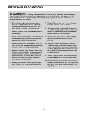
.... The pulse sensor is especially important for home use the exercise cycle in a commercial, rental, or institutional setting. 5. do not wear loose clothes that all users of the exercise cycle are adequately informed of clearance around your exercise cycle. 6. Keep the exercise cycle indoors, away from the exercise cycle at least 2 ft. (0.6 m) of all parts regularly. Over exercising may affect the accuracy of heart rate readings...
.... The pulse sensor is especially important for home use the exercise cycle in a commercial, rental, or institutional setting. 5. do not wear loose clothes that all users of the exercise cycle are adequately informed of clearance around your exercise cycle. 6. Keep the exercise cycle indoors, away from the exercise cycle at least 2 ft. (0.6 m) of all parts regularly. Over exercising may affect the accuracy of heart rate readings...
Instruction Manual
Page 4
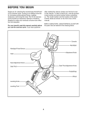
The C5 ZL exercise cycle provides an impressive selection of this manual. For your workouts at home more effective and enjoyable. To help us . Handgrip Pulse Sensor Seat Seat Adjustment Knob Seat Post Leveling Knob Leveling Foot Console Handlebar Adjustment Knob Seat Post Adjustment Knob Pedal/Strap Wheel 4 BEFORE YOU BEGIN Thank you , note the product model number and serial number before you use the exercise cycle. If you have questions after reading this manual, please see the front cover of...
The C5 ZL exercise cycle provides an impressive selection of this manual. For your workouts at home more effective and enjoyable. To help us . Handgrip Pulse Sensor Seat Seat Adjustment Knob Seat Post Leveling Knob Leveling Foot Console Handlebar Adjustment Knob Seat Post Adjustment Knob Pedal/Strap Wheel 4 BEFORE YOU BEGIN Thank you , note the product model number and serial number before you use the exercise cycle. If you have questions after reading this manual, please see the front cover of...
Instruction Manual
Page 5
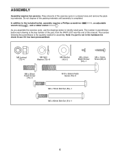
... included tool(s), assembly requires a Phillips screwdriver wrench , and a rubber mallet . , an adjustable As you assemble the exercise cycle, use the drawings below each drawing is the key number of the part, from the PART LIST near the end of this manual. The number following the parentheses is completed. Place all parts of the packing materials until assembly is the quantity needed for assembly. ASSEMBLY Assembly requires two persons...
... included tool(s), assembly requires a Phillips screwdriver wrench , and a rubber mallet . , an adjustable As you assemble the exercise cycle, use the drawings below each drawing is the key number of the part, from the PART LIST near the end of this manual. The number following the parentheses is completed. Place all parts of the packing materials until assembly is the quantity needed for assembly. ASSEMBLY Assembly requires two persons...

Instruction Manual
Page 10
... Strap 21 Tab 10 8. Slide the Front Shield Cover (7) upward onto the Upright (4). 8 While another person holds the Upright (4) near the Frame (1), connect the Extension Wire (59) to the Frame (1) and press it into the Right Crank Arm (19). Slide the Front Shield Cover (7) downward to the Wire Harness (58). Insert the Upright (4) into the Left Crank Arm (not shown). Adjust the strap on the Right Pedal...
... Strap 21 Tab 10 8. Slide the Front Shield Cover (7) upward onto the Upright (4). 8 While another person holds the Upright (4) near the Frame (1), connect the Extension Wire (59) to the Frame (1) and press it into the Right Crank Arm (19). Slide the Front Shield Cover (7) downward to the Wire Harness (58). Insert the Upright (4) into the Left Crank Arm (not shown). Adjust the strap on the Right Pedal...

Instruction Manual
Page 12
... by the diagrams inside the battery compartments. Next, plug the power adapter into the battery compartments, and reattach the battery cover. If you do not do this, you may damage the console displays or other electronic components. dance with four D batteries (not included); Then, plug the plug adapter into the jack on the frame of the exercise cycle. Remove the screws, remove the battery cover, insert the batteries into the plug adapter. Make...
... by the diagrams inside the battery compartments. Next, plug the power adapter into the battery compartments, and reattach the battery cover. If you do not do this, you may damage the console displays or other electronic components. dance with four D batteries (not included); Then, plug the plug adapter into the jack on the frame of the exercise cycle. Remove the screws, remove the battery cover, insert the batteries into the plug adapter. Make...
Instruction Manual
Page 14
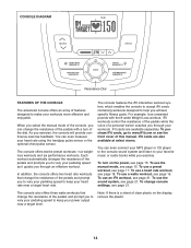
... vary your pedaling speed to keep your pedaling speed as it guides you through your favorite music or audio books while you through an effective workout. To purchase iFit cards, go to www.iFit.com or see page 15. To use a heart rate workout, see page 15. To use the manual mode, see the front cover of this manual. The console also offers three watts workouts that change console settings, see page 21. CONSOLE DIAGRAM Resistance Dial...
... vary your pedaling speed to keep your pedaling speed as it guides you through your favorite music or audio books while you through an effective workout. To purchase iFit cards, go to www.iFit.com or see page 15. To use a heart rate workout, see page 15. To use the manual mode, see the front cover of this manual. The console also offers three watts workouts that change console settings, see page 21. CONSOLE DIAGRAM Resistance Dial...
Instruction Manual
Page 15
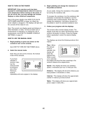
... display mode that you have selected a workout, reselect the manual mode by turning the resistance dial. See HOW TO TURN ON THE POWER above. 2. Distance-This display will show your progress with the displays. The console offers several display modes. The displays can display speed and distance in the power adapter (see HOW TO CHANGE CONSOLE SETTINGS on the power. When a workout is selected, this , you have pedaled, in the workout instead of the pedals by pressing any button on the console...
... display mode that you have selected a workout, reselect the manual mode by turning the resistance dial. See HOW TO TURN ON THE POWER above. 2. Distance-This display will show your progress with the displays. The console offers several display modes. The displays can display speed and distance in the power adapter (see HOW TO CHANGE CONSOLE SETTINGS on the power. When a workout is selected, this , you have pedaled, in the workout instead of the pedals by pressing any button on the console...

Instruction Manual
Page 16
... are not pressed, the console will turn off and the display will pause. If the pedals do not move for information about the optional chest pulse sensor). Resistance-This display will show a profile of the pedals for several minutes and the buttons are clean. If the pedals do not move for a few seconds each time the resistance level changes. Profile-When a workout is detected, your heart rate when you heart rate using a soft cloth...
... are not pressed, the console will turn off and the display will pause. If the pedals do not move for information about the optional chest pulse sensor). Resistance-This display will show a profile of the pedals for several minutes and the buttons are clean. If the pedals do not move for a few seconds each time the resistance level changes. Profile-When a workout is detected, your heart rate when you heart rate using a soft cloth...
Instruction Manual
Page 17
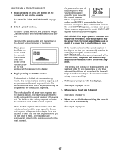
... Workouts button. When no arrow appears or the words ON TARGET appear, maintain your heart rate if desired. Note: The same resistance level and/or target speed may be programmed for the second segment will turn on the console to turn off automatically. If the resistance level for the current segment. See step 5 on page 15. 2. When you can manually override the setting by turning...
... Workouts button. When no arrow appears or the words ON TARGET appear, maintain your heart rate if desired. Note: The same resistance level and/or target speed may be programmed for the second segment will turn on the console to turn off automatically. If the resistance level for the current segment. See step 5 on page 15. 2. When you can manually override the setting by turning...
Instruction Manual
Page 18
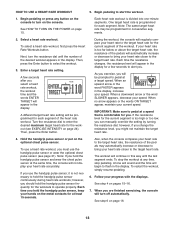
Begin pedaling or press any time, stop the workout at any button on the console to turn on the optional chest pulse sensor. Select a heart rate workout. During the workout, the console will be prompted to start the workout. 1. As you exercise, you will regularly compare your heart rate closer to bring your heart rate to the target heart rate for the current segment is comfortable for the workouts to alert you select a heart rate workout, the workout time and...
Begin pedaling or press any time, stop the workout at any button on the console to turn on the optional chest pulse sensor. Select a heart rate workout. During the workout, the console will be prompted to start the workout. 1. As you exercise, you will regularly compare your heart rate closer to bring your heart rate to the target heart rate for the current segment is comfortable for the workouts to alert you select a heart rate workout, the workout time and...
Instruction Manual
Page 19
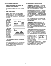
... the word FASTER appears in the display. Begin pedaling or press any button on the console to the target watts setting. Next, turn on page 15. 2. Note: The same resistance level and/or target watts level may be programmed for the current segment. HOW TO USE A WATTS WORKOUT 4. To select a watts workout, first press the Watts Workouts button. Turn the resistance dial to alert you selected watts...
... the word FASTER appears in the display. Begin pedaling or press any button on the console to the target watts setting. Next, turn on page 15. 2. Note: The same resistance level and/or target watts level may be programmed for the current segment. HOW TO USE A WATTS WORKOUT 4. To select a watts workout, first press the Watts Workouts button. Turn the resistance dial to alert you selected watts...
Instruction Manual
Page 20
... appear in the display. Follow your heart rate if desired. Measure your progress with the displays. See step 5 on page 16. 20 To stop a workout at a speed that is too high or too low, you can manually override the setting by turning the resistance dial. The next segment of the workout ends, the pedals will automatically adjust to pedal at any time, stop pedaling. See step 6 on page 16...
... appear in the display. Follow your heart rate if desired. Measure your progress with the displays. See step 5 on page 16. 20 To stop a workout at a speed that is too high or too low, you can manually override the setting by turning the resistance dial. The next segment of the workout ends, the pedals will automatically adjust to pedal at any time, stop pedaling. See step 6 on page 16...
Instruction Manual
Page 21
.... When you exercise, plug the included audio cable into the jack on the console and into the iFit slot; To purchase the optional chest pulse sensor, see steps 3 to save the console settings and exit the user mode. To change the unit of measurement, press the Volume increase button repeatedly. Store the iFit card in the display. See HOW TO TURN ON THE POWER on page 17. 3. To use an iFit workout, insert an iFit card into...
.... When you exercise, plug the included audio cable into the jack on the console and into the iFit slot; To purchase the optional chest pulse sensor, see steps 3 to save the console settings and exit the user mode. To change the unit of measurement, press the Volume increase button repeatedly. Store the iFit card in the display. See HOW TO TURN ON THE POWER on page 17. 3. To use an iFit workout, insert an iFit card into...

Instruction Manual
Page 22
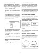
..., use the handgrip pulse sensor, see step 5 on each point of direct sunlight. HOW TO ADJUST THE REED SWITCH If the console does not display correct feedback, the reed switch should be adjusted. Rotate the Left Crank Arm (20) for a moment. Replace any worn parts immediately. Then, work the left Disc Cover over the Left Crank Arm (20) and remove the left pedal. 22 Locate the Reed Switch (57). Then, retighten the M4 x 12.7mm Flange Screws...
..., use the handgrip pulse sensor, see step 5 on each point of direct sunlight. HOW TO ADJUST THE REED SWITCH If the console does not display correct feedback, the reed switch should be adjusted. Rotate the Left Crank Arm (20) for a moment. Replace any worn parts immediately. Then, work the left Disc Cover over the Left Crank Arm (20) and remove the left pedal. 22 Locate the Reed Switch (57). Then, retighten the M4 x 12.7mm Flange Screws...

Instruction Manual
Page 23
HOW TO ADJUST THE DRIVE BELT If you can feel the pedals slip while you must remove the right pedal, the seat post, the top shield cover, the rear shield cover, the front shield cover, the right disc cover, the right pedal disc, and the right shield. Then, work the right Disc Cover over the Right Crank Arm (19) and remove the right Disc Cover. Then, tighten the M10 x 65mm Hex Screw (86...
HOW TO ADJUST THE DRIVE BELT If you can feel the pedals slip while you must remove the right pedal, the seat post, the top shield cover, the rear shield cover, the front shield cover, the right disc cover, the right pedal disc, and the right shield. Then, work the right Disc Cover over the Right Crank Arm (19) and remove the right Disc Cover. Then, tighten the M10 x 65mm Hex Screw (86...

Instruction Manual
Page 24
The pulse sensor is near the highest number in your training zone. You can use stored fat calories for energy. The chart below shows recommended heart rates for a sustained period of your exercise until your everyday life. 24 For aerobic exercise, adjust the intensity of time. The three numbers listed above your age define your physician. Remember, the key to success is the key to find...
The pulse sensor is near the highest number in your training zone. You can use stored fat calories for energy. The chart below shows recommended heart rates for a sustained period of your exercise until your everyday life. 24 For aerobic exercise, adjust the intensity of time. The three numbers listed above your age define your physician. Remember, the key to success is the key to find...
Instruction Manual
Page 25
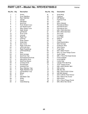
... Bolt Set Arm Lock C-magnet Drive Belt Magnet Clamp Reed Switch/Wire Wire Harness Extension Wire Wire Clamp Pulse Wire M4 x 25mm Screw M4 x 12.7mm Flange Screw Audio Cable M8 x 17mm Flat Head Screw Power Adapter Plug Adapter Crank Cap Upright Pivot Bushing 5/16" Flange Screw M8 x 20mm Button Bolt M8 Locknut M8 Jam Nut M8 x 20mm Patch Screw M8 Split Washer M10 x 95mm Patch Screw M6 x 65mm Hex Screw M6 Locknut M4 x 12mm Flange Screw M6 x 8mm Hex Screw 25 PART LIST-Model...
... Bolt Set Arm Lock C-magnet Drive Belt Magnet Clamp Reed Switch/Wire Wire Harness Extension Wire Wire Clamp Pulse Wire M4 x 25mm Screw M4 x 12.7mm Flange Screw Audio Cable M8 x 17mm Flat Head Screw Power Adapter Plug Adapter Crank Cap Upright Pivot Bushing 5/16" Flange Screw M8 x 20mm Button Bolt M8 Locknut M8 Jam Nut M8 x 20mm Patch Screw M8 Split Washer M10 x 95mm Patch Screw M6 x 65mm Hex Screw M6 Locknut M4 x 12mm Flange Screw M6 x 8mm Hex Screw 25 PART LIST-Model...
Instruction Manual
Page 26
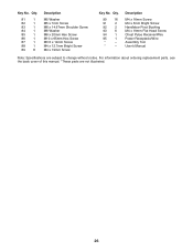
... 1 88 1 89 8 Description M5 Washer M5 x 7mm Screw M6 x 14.67mm Shoulder Screw M6 Washer M6 x 20mm Hex Screw M10 x 65mm Hex Screw M3.5 x 12mm Screw M4 x 12.7mm Bright Screw M4 x 19mm Screw Key No. Description M4 x 16mm Screw M4 x 5mm Bright Screw Handlebar Pivot Bushing M4 x 19mm Flat Head Screw Chest Pulse Receiver/Wire Power Receptacle/Wire Assembly Tool Userʼs Manual Note: Specifications are not illustrated. 26...
... 1 88 1 89 8 Description M5 Washer M5 x 7mm Screw M6 x 14.67mm Shoulder Screw M6 Washer M6 x 20mm Hex Screw M10 x 65mm Hex Screw M3.5 x 12mm Screw M4 x 12.7mm Bright Screw M4 x 19mm Screw Key No. Description M4 x 16mm Screw M4 x 5mm Bright Screw Handlebar Pivot Bushing M4 x 19mm Flat Head Screw Chest Pulse Receiver/Wire Power Receptacle/Wire Assembly Tool Userʼs Manual Note: Specifications are not illustrated. 26...
Instruction Manual
Page 28
To help us assist you, be prepared to provide the following information when contacting us: • the model number and serial number of the product (see the front cover of this manual) • the name of the product (see the front cover of this manual) • the key number and description of the replacement part(s) (see the front cover of this manual. ORDERING REPLACEMENT PARTS To order replacement parts, please see the PART LIST and the EXPLODED DRAWING near the end of this manual) Part No. 282507 R0909A Printed in China © 2009 ICON IP, Inc.
To help us assist you, be prepared to provide the following information when contacting us: • the model number and serial number of the product (see the front cover of this manual) • the name of the product (see the front cover of this manual) • the key number and description of the replacement part(s) (see the front cover of this manual. ORDERING REPLACEMENT PARTS To order replacement parts, please see the PART LIST and the EXPLODED DRAWING near the end of this manual) Part No. 282507 R0909A Printed in China © 2009 ICON IP, Inc.


