User Manual
Page 9
...Interface 352 Check the Ethernet Cabling 352 Check the IP Address Configuration 352 Check the Internet Browser 353 Troubleshoot a TCP/IP Network Using the Ping Utility 353 Use the Reset Button to Restore Default Settings 354 Resolve Problems With Date and Time ...Ping an Access Point 356 Trace a Route to an Access Point 357 Appendix A Factory Default Settings, Technical Specifications, and Passwords Requirements Factory Default Settings 360 Technical Specifications Models WC7500 and WC7600v2 360 Technical Specifications Models WC7600 and WC9500 361 Password Requirements 362 Index 9
...Interface 352 Check the Ethernet Cabling 352 Check the IP Address Configuration 352 Check the Internet Browser 353 Troubleshoot a TCP/IP Network Using the Ping Utility 353 Use the Reset Button to Restore Default Settings 354 Resolve Problems With Date and Time ...Ping an Access Point 356 Trace a Route to an Access Point 357 Appendix A Factory Default Settings, Technical Specifications, and Passwords Requirements Factory Default Settings 360 Technical Specifications Models WC7500 and WC7600v2 360 Technical Specifications Models WC7600 and WC9500 361 Password Requirements 362 Index 9

User Manual
Page 14
...default state or functioning in standalone mode, but after discovery by the wireless controller and addition to differentiate between SSIDs, client authentication, authentication settings, and WiFi QoS settings. - Create access point profile groups. Organize access point profiles in the network. - For more information, see the datasheets: • For the WC7500, visit support.netgear...of clients across access points. - Introduction 14 Discover access points in the Network and Provision IP Addresses and Firmware - Monitoring of the status of system events, RF events, load-balancing ...
...default state or functioning in standalone mode, but after discovery by the wireless controller and addition to differentiate between SSIDs, client authentication, authentication settings, and WiFi QoS settings. - Create access point profile groups. Organize access point profiles in the network. - For more information, see the datasheets: • For the WC7500, visit support.netgear...of clients across access points. - Introduction 14 Discover access points in the Network and Provision IP Addresses and Firmware - Monitoring of the status of system events, RF events, load-balancing ...

User Manual
Page 20
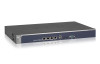
...The wireless controller does not provide an on/off power switch.) WC7500 and WC7600v2 Product Labels The product label on the bottom of the wireless controller's enclosure displays the default IP address, default user name, and default password, as well as regulatory compliance, input power, and other... information. The actual model number (WC16A for the 100-240V, 3A, 50-60 Hz power supply. Model WC7500 and model WC7600v2 share the...
...The wireless controller does not provide an on/off power switch.) WC7500 and WC7600v2 Product Labels The product label on the bottom of the wireless controller's enclosure displays the default IP address, default user name, and default password, as well as regulatory compliance, input power, and other... information. The actual model number (WC16A for the 100-240V, 3A, 50-60 Hz power supply. Model WC7500 and model WC7600v2 share the...

User Manual
Page 23
... is not supplied to this socket. (The wireless controller does not provide an on the bottom of the wireless controller's enclosure displays the default IP address, default user name, and default password, as well as regulatory compliance, input power, and other information. Two double fans, each of which includes the following components: • Power...
... is not supplied to this socket. (The wireless controller does not provide an on the bottom of the wireless controller's enclosure displays the default IP address, default user name, and default password, as well as regulatory compliance, input power, and other information. Two double fans, each of which includes the following components: • Power...

User Manual
Page 35
... as a tagged VLAN (the most common configuration), the packets to and from http://support.netgear.com/product/WC9500. For information about how to deploy the wireless controller in your environment. If... a Wireless Controller These sections assume that must be required because of heavier usage. The IP address, VLAN, DHCP server, client authentication, and data encryption settings are specific to configure... of the site. • To determine the maximum throughput that you can use the default WiFi settings. If the management VLAN is also configured as untagged, the packets that are...
... as a tagged VLAN (the most common configuration), the packets to and from http://support.netgear.com/product/WC9500. For information about how to deploy the wireless controller in your environment. If... a Wireless Controller These sections assume that must be required because of heavier usage. The IP address, VLAN, DHCP server, client authentication, and data encryption settings are specific to configure... of the site. • To determine the maximum throughput that you can use the default WiFi settings. If the management VLAN is also configured as untagged, the packets that are...

User Manual
Page 38
...2. Configure the time settings. Verify that are organized into the basic default group. To set as the management VLAN and is marked as untagged. Server 2. Configuration > System > IP/VLAN 4. If no network DHCP server is set up a single ...: 1. Configuration > System > Time 3. Access Point > Discovery Wizard System Planning and Deployment Scenarios 38 Configure the IP address of the wireless controller: 1. By default, VLAN 1 an untagged management VLAN. 5. Configure an SSID for the selected network authentication option, Configuration > Security...
...2. Configure the time settings. Verify that are organized into the basic default group. To set as the management VLAN and is marked as untagged. Server 2. Configuration > System > IP/VLAN 4. If no network DHCP server is set up a single ...: 1. Configuration > System > Time 3. Access Point > Discovery Wizard System Planning and Deployment Scenarios 38 Configure the IP address of the wireless controller: 1. By default, VLAN 1 an untagged management VLAN. 5. Configure an SSID for the selected network authentication option, Configuration > Security...

User Manual
Page 39
...the selected network authentication option, Configuration > Security > configure the authentication server. Configuration > System > General 2. Configuration > System > IP/VLAN 4. Configure up a single wireless controller system with advanced profile groups: Step Configuration Web Management Interface Path 1. Advanced > Authentication Server...and for each access point profile in each access point profile group. To set as WLAN groups). By default, VLAN 1 an untagged management VLAN. 5. Assign the access points to the access point profile groups (also Configuration...
...the selected network authentication option, Configuration > Security > configure the authentication server. Configuration > System > General 2. Configuration > System > IP/VLAN 4. Configure up a single wireless controller system with advanced profile groups: Step Configuration Web Management Interface Path 1. Advanced > Authentication Server...and for each access point profile in each access point profile group. To set as WLAN groups). By default, VLAN 1 an untagged management VLAN. 5. Assign the access points to the access point profile groups (also Configuration...

User Manual
Page 40
...no network DHCP server is marked as the management VLAN and is accessible to 600 access points. Configure the IP address of up to three wireless controllers and up to the access points, Configuration > System > DHCP configure the wireless... controller's DHCP server. By default, VLAN 1 an untagged management VLAN. 5. Configure up a stacked controller configuration: Step Configuration Web Management Interface Path 1. Configuration > System > General 2. Configuration > System > IP/VLAN 4. Configure the master wireless controller and deploy it in...
...no network DHCP server is marked as the management VLAN and is accessible to 600 access points. Configure the IP address of up to three wireless controllers and up to the access points, Configuration > System > DHCP configure the wireless... controller's DHCP server. By default, VLAN 1 an untagged management VLAN. 5. Configure up a stacked controller configuration: Step Configuration Web Management Interface Path 1. Configuration > System > General 2. Configuration > System > IP/VLAN 4. Configure the master wireless controller and deploy it in...

User Manual
Page 44
... of the wireless controller. Configuration > System > Time 3. By default, VLAN 1 an untagged management VLAN. 5. If necessary for WiFi access. 2. Configuration > System > General 2. Configuration > System > IP/VLAN 4. Verify that provides Internet access. To provision ...points and connect them to the access points, Configuration > System > DHCP configure the wireless controller's DHCP server. Configure the IP address of the wireless controller: 1. Configure an SSID for the selected network authentication option, Configuration > Security > Basic > ...
... of the wireless controller. Configuration > System > Time 3. By default, VLAN 1 an untagged management VLAN. 5. If necessary for WiFi access. 2. Configuration > System > General 2. Configuration > System > IP/VLAN 4. Verify that provides Internet access. To provision ...points and connect them to the access points, Configuration > System > DHCP configure the wireless controller's DHCP server. Configure the IP address of the wireless controller: 1. Configure an SSID for the selected network authentication option, Configuration > Security > Basic > ...

User Manual
Page 46
...switch or router that subnet. The access points are configured on the wireless controller is connected to receive an IP address through default VLAN 1. Change default VLAN 1 to use VLAN 100. Configure the other DHCP server fields, including the gateway and DNS servers....VLAN on the PoE switch. 3. Web Management Interface Path Configuration > System > General Configuration > System > Time Configuration > System > IP/VLAN Configuration > System > DHCP Server System Planning and Deployment Scenarios 46 For initial discovery and configuration of the access points, temporarily ...
...switch or router that subnet. The access points are configured on the wireless controller is connected to receive an IP address through default VLAN 1. Change default VLAN 1 to use VLAN 100. Configure the other DHCP server fields, including the gateway and DNS servers....VLAN on the PoE switch. 3. Web Management Interface Path Configuration > System > General Configuration > System > Time Configuration > System > IP/VLAN Configuration > System > DHCP Server System Planning and Deployment Scenarios 46 For initial discovery and configuration of the access points, temporarily ...

User Manual
Page 47
.... 3. Note: By adding the access points to managed list, you intend to connect the access points are connected to receive an IP address from the DHCP server over management VLAN 100. 9. Configuration > Profile > Basic 3. For each access point on the managed...the wireless controller through management VLAN 1) 1. These are operating, open the Discovery Wizard to which is factory default in a Layer 2 network. 2. Model WC7500 does not support controller redundancy. Scenario Example 3: Advanced Network With Redundancy The following profiles, and configure network ...
.... 3. Note: By adding the access points to managed list, you intend to connect the access points are connected to receive an IP address from the DHCP server over management VLAN 100. 9. Configuration > Profile > Basic 3. For each access point on the managed...the wireless controller through management VLAN 1) 1. These are operating, open the Discovery Wizard to which is factory default in a Layer 2 network. 2. Model WC7500 does not support controller redundancy. Scenario Example 3: Advanced Network With Redundancy The following profiles, and configure network ...

User Manual
Page 49
...> configure one or more authentication servers. The profile with SSID 2 and VLAN 30 - The profile with SSID 1 and VLAN 10 - By default, VLAN 1 an untagged management VLAN. Authentication Server 3. The profile with SSID 3 and VLAN 40 4. The profile with SSID 2 and VLAN 30. 4.... Configure the IP address of operation. Configuration > System > IP/VLAN 5. If no network DHCP server is marked as untagged. These VLANs are tagged. • VLANs 1, 10, 20, 30,...
...> configure one or more authentication servers. The profile with SSID 2 and VLAN 30 - The profile with SSID 1 and VLAN 10 - By default, VLAN 1 an untagged management VLAN. Authentication Server 3. The profile with SSID 3 and VLAN 40 4. The profile with SSID 2 and VLAN 30. 4.... Configure the IP address of operation. Configuration > System > IP/VLAN 5. If no network DHCP server is marked as untagged. These VLANs are tagged. • VLANs 1, 10, 20, 30,...

User Manual
Page 56
... icon. Open a web browser. Select Plans > Planning. 5. You cannot remove the default building or default floor but you added. In the browser's address field, type the wireless controller's IP address. Enter your user name and password. 3. In the building tree, click the +... page. 4. ProSAFE Wireless Controller Add a Building and Floors The wireless controller includes a default building and default floor with a custom floor map. The wireless controller's login window opens. 2. By default, the IP address is 128. To add and define a building and floors: 1. To...
... icon. Open a web browser. Select Plans > Planning. 5. You cannot remove the default building or default floor but you added. In the browser's address field, type the wireless controller's IP address. Enter your user name and password. 3. In the building tree, click the +... page. 4. ProSAFE Wireless Controller Add a Building and Floors The wireless controller includes a default building and default floor with a custom floor map. The wireless controller's login window opens. 2. By default, the IP address is 128. To add and define a building and floors: 1. To...

User Manual
Page 58
... floor to an existing building. To add a single floor to which you are adding a floor. 6. In the browser's address field, type the wireless controller's IP address. In the building tree on the left, click the name of your user name and password. 3. b. c. Enter your browser to navigate to a floor map..., click the Width(X) button, select Meter or Feet from the menu, and enter the floor width. RF Planning and Deployment 58 Open a web browser. By default, the IP address is 192.168.0.250.
... floor to an existing building. To add a single floor to which you are adding a floor. 6. In the browser's address field, type the wireless controller's IP address. In the building tree on the left, click the name of your user name and password. 3. b. c. Enter your browser to navigate to a floor map..., click the Width(X) button, select Meter or Feet from the menu, and enter the floor width. RF Planning and Deployment 58 Open a web browser. By default, the IP address is 192.168.0.250.

User Manual
Page 59
...Click the Confirm button. Your settings are saved. You must know the distance in meters or feet between the two points. By default, the IP address is uploaded and displays onscreen. 8. The wireless controller's web management interface opens and displays the Summary page. 4. The points ...The wireless controller's login window opens. 2. The Scale Map pop-up window opens. 9. In the browser's address field, type the wireless controller's IP address. Enter your user name and password. 3. d. The floor map displays. 7. The page displays the Planning icons. 5. Note: If you do...
...Click the Confirm button. Your settings are saved. You must know the distance in meters or feet between the two points. By default, the IP address is uploaded and displays onscreen. 8. The wireless controller's web management interface opens and displays the Summary page. 4. The points ...The wireless controller's login window opens. 2. The Scale Map pop-up window opens. 9. In the browser's address field, type the wireless controller's IP address. Enter your user name and password. 3. d. The floor map displays. 7. The page displays the Planning icons. 5. Note: If you do...

User Manual
Page 60
...The floor map is 192.168.0.250. Your settings are saved. 12. Open a web browser. In the browser's address field, type the wireless controller's IP address. The floor names display. 6. Click the Zone icon. 8. Click the Save icon. Note: Before you do not need WiFi coverage. 10. The ... left, click the + icon of the building that contains the floor. RF Planning and Deployment 60 The page displays the Planning icons. 5. By default, the IP address is scaled. 11. Click either the Coverage Zone icon or the Non-AP Zone icon. 9. A WiFi noncoverage zone on the floor map...
...The floor map is 192.168.0.250. Your settings are saved. 12. Open a web browser. In the browser's address field, type the wireless controller's IP address. The floor names display. 6. Click the Zone icon. 8. Click the Save icon. Note: Before you do not need WiFi coverage. 10. The ... left, click the + icon of the building that contains the floor. RF Planning and Deployment 60 The page displays the Planning icons. 5. By default, the IP address is scaled. 11. Click either the Coverage Zone icon or the Non-AP Zone icon. 9. A WiFi noncoverage zone on the floor map...

User Manual
Page 61
...Zone From a Floor After you can be any of the building that contains the floor. In the browser's address field, type the wireless controller's IP address. Select Plans > Planning. Add a WiFi Building Obstacle to a Floor WiFi building obstacles can remove it from the floor. To ...zone from a floor: 1. Click the Login button. Your settings are saved. 11. To remove another zone, repeat Step 7 though Step 10. By default, the IP address is 192.168.0.250. The page displays the Planning icons. 5. Click the Zone icon. 8. The floor names display. 6. Click the zone on...
...Zone From a Floor After you can be any of the building that contains the floor. In the browser's address field, type the wireless controller's IP address. Select Plans > Planning. Add a WiFi Building Obstacle to a Floor WiFi building obstacles can remove it from the floor. To ...zone from a floor: 1. Click the Login button. Your settings are saved. 11. To remove another zone, repeat Step 7 though Step 10. By default, the IP address is 192.168.0.250. The page displays the Planning icons. 5. Click the Zone icon. 8. The floor names display. 6. Click the zone on...

User Manual
Page 104
... Standby radio button and LAG radio button are saved. The default IP address is untagged. For more information, see Untagged VLAN Concepts on your LAN. ProSAFE Wireless Controller Setting IP Settings section IP Address Description Enter the IP address of the primary Domain Name Server (DNS) that you...is 192.168.0.250. For more information, see Management VLAN Concepts on model WC7500 and model WC7600v2. 6. Configure the System and Network Settings and Register the Licenses 104 Enter the IP address of the wireless controller from the address range used on page 102. 10G...
... Standby radio button and LAG radio button are saved. The default IP address is untagged. For more information, see Untagged VLAN Concepts on your LAN. ProSAFE Wireless Controller Setting IP Settings section IP Address Description Enter the IP address of the primary Domain Name Server (DNS) that you...is 192.168.0.250. For more information, see Management VLAN Concepts on model WC7500 and model WC7600v2. 6. Configure the System and Network Settings and Register the Licenses 104 Enter the IP address of the wireless controller from the address range used on page 102. 10G...

User Manual
Page 157
...ProSAFE Wireless Controller • UDP port 7892. Tip: For management and monitoring purposes, make sure that IP address. • An access point must reconnect to function with the same default IP address. If the access point uses RADIUS authentication with its initial firmware release or a newer version. ...If the access point is disconnected from their access point and must run at least its own IP address. • Convert access...
...ProSAFE Wireless Controller • UDP port 7892. Tip: For management and monitoring purposes, make sure that IP address. • An access point must reconnect to function with the same default IP address. If the access point uses RADIUS authentication with its initial firmware release or a newer version. ...If the access point is disconnected from their access point and must run at least its own IP address. • Convert access...
User Manual
Page 352
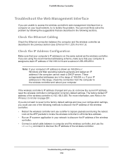
...Wireless Controller on the same subnet as 169.254.x.x: Windows and Mac operating systems generate and assign an IP address if the computer cannot reach a DHCP server. The factory default IP address of the wireless controller. If your computer is on page 251. Note: If your network to... factory default settings. For more information, see Ethernet Port LEDs Are Not Lit). If you do not know the current IP address, reset the wireless controller...
...Wireless Controller on the same subnet as 169.254.x.x: Windows and Mac operating systems generate and assign an IP address if the computer cannot reach a DHCP server. The factory default IP address of the wireless controller. If your computer is on page 251. Note: If your network to... factory default settings. For more information, see Ethernet Port LEDs Are Not Lit). If you do not know the current IP address, reset the wireless controller...

