
Hardware Installation Guide
Page 4
... (SFP) combo ports, and USB console selection slide switch, and USB console port. 4 Introduction 1 The NETGEAR ProSafe® 4100 series managed switches provide state-of the ProSafe 4100 series managed switches. 1. For information about features for ... LEDs The following : M4100-26G M4100-50G M4100-26-POE M4100-26G-POE M4100-50G-POE+ M4100-50-POE M4100-D10-POE M4100-D12G M4100-12GF M4100-D12G-POE+ M4100-24G-POE+ M4100-12G-POE+ This guide describes hardware installation and basic troubleshooting for each product, visit the NETGEAR website at http://www.netgear.com. These switches can...
... (SFP) combo ports, and USB console selection slide switch, and USB console port. 4 Introduction 1 The NETGEAR ProSafe® 4100 series managed switches provide state-of the ProSafe 4100 series managed switches. 1. For information about features for ... LEDs The following : M4100-26G M4100-50G M4100-26-POE M4100-26G-POE M4100-50G-POE+ M4100-50-POE M4100-D10-POE M4100-D12G M4100-12GF M4100-D12G-POE+ M4100-24G-POE+ M4100-12G-POE+ This guide describes hardware installation and basic troubleshooting for each product, visit the NETGEAR website at http://www.netgear.com. These switches can...

Hardware Installation Guide
Page 5
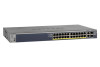
M4100-50-POE front panel POE ports RJ-45 ports SFP ports 5 M4100-26-POE front panel POE ports RJ-45 ports SFP ports LEDs USB port Reset button Figure 4. NETGEAR Managed Switch LEDs USB port Reset button Figure 1. M4100-50G front panel RJ-45 ports SFP SPD/Link/ACT mode: Green = Link at 1G Yellow = Link at 100M Blink = ACT SFP ports LEDs USB port Reset button Figure 3. M4100-26G front panel RJ-45 ports SFP ports Combo Ports Power Fan RPS Reset USB RJ45 SPD/Link/ACT mode: Green = 1G Yellow = 10/100M Blink = ACT LEDs USB port Reset button Figure 2.
M4100-50-POE front panel POE ports RJ-45 ports SFP ports 5 M4100-26-POE front panel POE ports RJ-45 ports SFP ports LEDs USB port Reset button Figure 4. NETGEAR Managed Switch LEDs USB port Reset button Figure 1. M4100-50G front panel RJ-45 ports SFP SPD/Link/ACT mode: Green = Link at 1G Yellow = Link at 100M Blink = ACT SFP ports LEDs USB port Reset button Figure 3. M4100-26G front panel RJ-45 ports SFP ports Combo Ports Power Fan RPS Reset USB RJ45 SPD/Link/ACT mode: Green = 1G Yellow = 10/100M Blink = ACT LEDs USB port Reset button Figure 2.

Hardware Installation Guide
Page 8
...module is connected to PSE getting 802.3af specified power. Solid yellow: The fan has failed. Note: Only for M4100-26G, 50G, 26-POE, 26G-POE, 50G-POE+, and 50-POE Solid green: PD port 1 is present but RPS has failed. Solid green: A valid 1000 Mbps link is ...M4100-D12G, -24G-POE, D12G-POE, 12G-POE+, -12GF Solid yellow: Indicates less than 7 watts of the following failures resulted in stopping power to PSE getting 802.3at specified power. NETGEAR Managed Switch Table 1. Note: Only for another device. Off: No link is established on the port. Solid green: The PoE...
...module is connected to PSE getting 802.3af specified power. Solid yellow: The fan has failed. Note: Only for M4100-26G, 50G, 26-POE, 26G-POE, 50G-POE+, and 50-POE Solid green: PD port 1 is present but RPS has failed. Solid green: A valid 1000 Mbps link is ...M4100-D12G, -24G-POE, D12G-POE, 12G-POE+, -12GF Solid yellow: Indicates less than 7 watts of the following failures resulted in stopping power to PSE getting 802.3at specified power. NETGEAR Managed Switch Table 1. Note: Only for another device. Off: No link is established on the port. Solid green: The PoE...

Hardware Installation Guide
Page 9
... have a DB9 console port, a mini USB port (only for M4100-26G, 50G, 26-POE, 26G-POE, 50G-POE+, 50-POE, D12-PoE, and D12G), a redundant power supply connector (only for M4100-26G, 50G, 26-POE, 26G-POE, 50G-POE+, 50-POE, 12GF, 24G-POE+, and 12G-POE+), and a standard AC power receptacle for the supplied power cord. ...power from PSE successfully. Solid yellow: The PSE is established on the port. Blinking green: The port is established on the port. NETGEAR Managed Switch Table 1. Note: If a combo port media changes to fiber, the copper port LED changes to off status. Off:...
... have a DB9 console port, a mini USB port (only for M4100-26G, 50G, 26-POE, 26G-POE, 50G-POE+, 50-POE, D12-PoE, and D12G), a redundant power supply connector (only for M4100-26G, 50G, 26-POE, 26G-POE, 50G-POE+, 50-POE, 12GF, 24G-POE+, and 12G-POE+), and a standard AC power receptacle for the supplied power cord. ...power from PSE successfully. Solid yellow: The PSE is established on the port. Blinking green: The port is established on the port. NETGEAR Managed Switch Table 1. Note: If a combo port media changes to fiber, the copper port LED changes to off status. Off:...

Hardware Installation Guide
Page 20
...properly and securely. To apply AC power: 1. Note: The M4100-26G, 50G, 26-PoE, 26G-PoE, 50-PoE+, 50G-PoE, 12GF, 24G-POE+, 12G-POE+ can provide full power to these switches to the switch). Note: Normally the M4100-D12G and M4100-D12G-POE+ will not create a safety hazard. 4. The only way ...2. Inspect the equipment thoroughly. 2. Check cable routing to ensure that is working and ready to a grounded three-pronged AC outlet. NETGEAR Managed Switch Check the Installation Before you connect the power cord, select an AC outlet that cables are not damaged and will get ...
...properly and securely. To apply AC power: 1. Note: The M4100-26G, 50G, 26-PoE, 26G-PoE, 50-PoE+, 50G-PoE, 12GF, 24G-POE+, 12G-POE+ can provide full power to these switches to the switch). Note: Normally the M4100-D12G and M4100-D12G-POE+ will not create a safety hazard. 4. The only way ...2. Inspect the equipment thoroughly. 2. Check cable routing to ensure that is working and ready to a grounded three-pronged AC outlet. NETGEAR Managed Switch Check the Installation Before you connect the power cord, select an AC outlet that cables are not damaged and will get ...

Hardware Installation Guide
Page 28
Fast Ethernet switches physical specifications Fast Ethernet Switches M4100-26-POE (FSM7226P) M4100-50-POE (FSM7250P) M4100-D10-POE (FSM5210P) Interface (AutoUplink on all RJ-45 ports) 24 RJ-45 ports for 10/100 ...2 SFP ports for 100/1000 Mbps 2 SFP ports for 100/1000 Mbps 2 SFP ports for 100/1000 Mbps 24 PoE ports 48 IEEE802.3af PoE 8 IEEE802.3af PoE 1 USB type A connector ports ports RS-232 console port 1 USB type A connector 1 USB type A connector 1...power consumption (W) (100-240V AC, 50-60 Hz) 456.29 486.64 87.30 Technical Specifications 28 NETGEAR Managed Switch Table 6.
Fast Ethernet switches physical specifications Fast Ethernet Switches M4100-26-POE (FSM7226P) M4100-50-POE (FSM7250P) M4100-D10-POE (FSM5210P) Interface (AutoUplink on all RJ-45 ports) 24 RJ-45 ports for 10/100 ...2 SFP ports for 100/1000 Mbps 2 SFP ports for 100/1000 Mbps 2 SFP ports for 100/1000 Mbps 24 PoE ports 48 IEEE802.3af PoE 8 IEEE802.3af PoE 1 USB type A connector ports ports RS-232 console port 1 USB type A connector 1 USB type A connector 1...power consumption (W) (100-240V AC, 50-60 Hz) 456.29 486.64 87.30 Technical Specifications 28 NETGEAR Managed Switch Table 6.
CLI Manual
Page 734
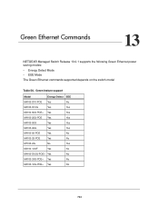
... Energy-Detect EEE M4100-D10-POE Yes No M4100-D12G Yes Yes M4100-50G-POE+ Yes Yes M4100-26G-POE Yes Yes M4100-50G Yes Yes M4100-26G Yes Yes M4100-50-POE Yes No M4100-26-POE Yes No M7100-24x No Yes M4100-12GF Yes No M4100-D12G-POE+ Yes No M4100-24G-POE+ Yes No M4100-12G-POE+ Yes No 734 Green Ethernet Commands 13 NETGEAR Managed Switch Release...
... Energy-Detect EEE M4100-D10-POE Yes No M4100-D12G Yes Yes M4100-50G-POE+ Yes Yes M4100-26G-POE Yes Yes M4100-50G Yes Yes M4100-26G Yes Yes M4100-50-POE Yes No M4100-26-POE Yes No M7100-24x No Yes M4100-12GF Yes No M4100-D12G-POE+ Yes No M4100-24G-POE+ Yes No M4100-12G-POE+ Yes No 734 Green Ethernet Commands 13 NETGEAR Managed Switch Release...


