
Hardware Installation Guide
Page 4
...Front Panels and LEDs The following : M4100-26G M4100-50G M4100-26-POE M4100-26G-POE M4100-50G-POE+ M4100-50-POE M4100-D10-POE M4100-D12G M4100-12GF M4100-D12G-POE+ M4100-24G-POE+ M4100-12G-POE+ This guide describes hardware installation and basic troubleshooting for each product, visit the NETGEAR website at http://www.netgear.com. For information about features for these...freestanding, wall mounted, or rack mounted in a wiring closet or an equipment room. Introduction 1 The NETGEAR ProSafe® 4100 series managed switches provide state-of the ProSafe 4100 series managed switches.
...Front Panels and LEDs The following : M4100-26G M4100-50G M4100-26-POE M4100-26G-POE M4100-50G-POE+ M4100-50-POE M4100-D10-POE M4100-D12G M4100-12GF M4100-D12G-POE+ M4100-24G-POE+ M4100-12G-POE+ This guide describes hardware installation and basic troubleshooting for each product, visit the NETGEAR website at http://www.netgear.com. For information about features for these...freestanding, wall mounted, or rack mounted in a wiring closet or an equipment room. Introduction 1 The NETGEAR ProSafe® 4100 series managed switches provide state-of the ProSafe 4100 series managed switches.

Hardware Installation Guide
Page 7
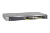
NETGEAR Managed Switch Power Fan PD MaxPoE Reset USB PoE (Max 30W per port): Off = No PD Green = PoE Powered Yellow = PoE Fault PoE-PD (Port 1, 2): Off = No PSE Green = PSE 30w Yellow = PSE 15.4w RJ45 SPD/Link/ACT mode: Green = 1G Yellow = 10/100M Blink = ACT PoE SPD/Link/ACT LEDs USB port .../Link/ACT RJ45 SPD/Link/ACT mode: Green = 1G Yellow = 10/100M Blink = ACT LEDs USB port Reset button Figure 9. M4100-24G-POE+ front panel SPD/Link/ACT M4100-24G-POE+ SFP SPD/Link/ACT mode Green = Link at 1G Yellow = Link at 100M Blink = ACT SPD/Link/ACT LEDs USB Port Reset button Figure...
NETGEAR Managed Switch Power Fan PD MaxPoE Reset USB PoE (Max 30W per port): Off = No PD Green = PoE Powered Yellow = PoE Fault PoE-PD (Port 1, 2): Off = No PSE Green = PSE 30w Yellow = PSE 15.4w RJ45 SPD/Link/ACT mode: Green = 1G Yellow = 10/100M Blink = ACT PoE SPD/Link/ACT LEDs USB port .../Link/ACT RJ45 SPD/Link/ACT mode: Green = 1G Yellow = 10/100M Blink = ACT LEDs USB port Reset button Figure 9. M4100-24G-POE+ front panel SPD/Link/ACT M4100-24G-POE+ SFP SPD/Link/ACT mode Green = Link at 1G Yellow = Link at 100M Blink = ACT SPD/Link/ACT LEDs USB Port Reset button Figure...

Hardware Installation Guide
Page 8
...present but RPS has failed. Note: Only for M4100-D12G, -24G-POE, D12G-POE, 12G-POE+, -12GF Solid yellow: Indicates less than 7 watts of PoE power available for at 1000 Mbps. Note: Only for M4100-26G, 50G, 26-POE, 26G-POE, 50G-POE+, and 50-POE Solid green: PD port 1 is available. Off... yellow: Power module is present but has failed. Off: There is established on the port at 10/100 Mbps. PoE current exceeds PD's classification - NETGEAR Managed Switch Table 1. Solid yellow: The fan has failed. Off: RPS disconnected. Blinking yellow: Packet transmission or reception...
...present but RPS has failed. Note: Only for M4100-D12G, -24G-POE, D12G-POE, 12G-POE+, -12GF Solid yellow: Indicates less than 7 watts of PoE power available for at 1000 Mbps. Note: Only for M4100-26G, 50G, 26-POE, 26G-POE, 50G-POE+, and 50-POE Solid green: PD port 1 is available. Off... yellow: Power module is present but has failed. Off: There is established on the port at 10/100 Mbps. PoE current exceeds PD's classification - NETGEAR Managed Switch Table 1. Solid yellow: The fan has failed. Off: RPS disconnected. Blinking yellow: Packet transmission or reception...

Hardware Installation Guide
Page 9
NETGEAR Managed Switch Table 1. Note: If a combo port media changes to fiber, ... link is established on the port. Off: No link is established on the port. M4100-26G, 50G, 26-POE, 26G-POE, 50G-POE+, and 50-POE rear panels 9 PoE-PD Off: No PSE is connected or PSE is established on the port at 1000...console port, a mini USB port (only for M4100-26G, 50G, 26-POE, 26G-POE, 50G-POE+, 50-POE, D12-PoE, and D12G), a redundant power supply connector (only for M4100-26G, 50G, 26-POE, 26G-POE, 50G-POE+, 50-POE, 12GF, 24G-POE+, and 12G-POE+), and a standard AC power receptacle for the ...
NETGEAR Managed Switch Table 1. Note: If a combo port media changes to fiber, ... link is established on the port. Off: No link is established on the port. M4100-26G, 50G, 26-POE, 26G-POE, 50G-POE+, and 50-POE rear panels 9 PoE-PD Off: No PSE is connected or PSE is established on the port at 1000...console port, a mini USB port (only for M4100-26G, 50G, 26-POE, 26G-POE, 50G-POE+, 50-POE, D12-PoE, and D12G), a redundant power supply connector (only for M4100-26G, 50G, 26-POE, 26G-POE, 50G-POE+, 50-POE, 12GF, 24G-POE+, and 12G-POE+), and a standard AC power receptacle for the ...

Hardware Installation Guide
Page 10
M4100-12GF, 24G-POE+, 12G-POE+ rear panel AC power connector Lock Console port Figure 16. M4100-D12G-POE+ rear panel AC power connector Safety Instructions Use the following precautions. • Observe and follow service markings. - NETGEAR Managed Switch Console switch Console ports Lock Power adapter connector Figure 14. To reduce the risk of bodily injury, electrical shock...
M4100-12GF, 24G-POE+, 12G-POE+ rear panel AC power connector Lock Console port Figure 16. M4100-D12G-POE+ rear panel AC power connector Safety Instructions Use the following precautions. • Observe and follow service markings. - NETGEAR Managed Switch Console switch Console ports Lock Power adapter connector Figure 14. To reduce the risk of bodily injury, electrical shock...

Hardware Installation Guide
Page 17
M4100-24G-POE+ Mounting bracket 3. Tighten the screws with a No. 2 Phillips screwdriver to the rack. 5. Tighten the screws with a No. 1 Phillips screwdriver to secure each bracket to secure the switch in the rack. Align the bracket and rack holes. Hardware Installation 17 Use two pan-head screws with nylon washers to the sides of the switch. Use the provided Phillips head screws to fasten the brackets to fasten each bracket. 4. NETGEAR Managed Switch 2.
M4100-24G-POE+ Mounting bracket 3. Tighten the screws with a No. 2 Phillips screwdriver to the rack. 5. Tighten the screws with a No. 1 Phillips screwdriver to secure each bracket to secure the switch in the rack. Align the bracket and rack holes. Hardware Installation 17 Use two pan-head screws with nylon washers to the sides of the switch. Use the provided Phillips head screws to fasten the brackets to fasten each bracket. 4. NETGEAR Managed Switch 2.

Hardware Installation Guide
Page 20
...the switch). The LED should support IEEE802.3at so that cables are not damaged and will get power from an RPS. Hardware Installation 20 NETGEAR Managed Switch Check the Installation Before you connect the power cord, select an AC outlet that all cables are the RPS5412 and RPS4000. Connect... runs a power-on self-test (POST). • If the switch passes the test, the LED turns green. Note: The M4100-26G, 50G, 26-PoE, 26G-PoE, 50-PoE+, 50G-PoE, 12GF, 24G-POE+, 12G-POE+ can turn off switch. The only way to apply or remove power is working and ready to connect or disconnect the...
...the switch). The LED should support IEEE802.3at so that cables are not damaged and will get power from an RPS. Hardware Installation 20 NETGEAR Managed Switch Check the Installation Before you connect the power cord, select an AC outlet that all cables are the RPS5412 and RPS4000. Connect... runs a power-on self-test (POST). • If the switch passes the test, the LED turns green. Note: The M4100-26G, 50G, 26-PoE, 26G-PoE, 50-PoE+, 50G-PoE, 12GF, 24G-POE+, 12G-POE+ can turn off switch. The only way to apply or remove power is working and ready to connect or disconnect the...
Hardware Installation Guide
Page 27
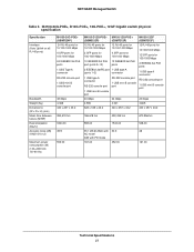
... failure (MTBF) Heat dissipation (Btu/hr) Acoustic noise (dB) (ANSI-S10.12) Maximum power consumption (W) (100-240V AC, 50-60 Hz) M4100-24G-POE+ (GSM7224P) 24 RJ-45 ports for 10/100/1000 Mbps 4 SFP ports for 100/1000 Mbps 24 IEEE802.3at...A connector RS-232 console port 1 USB mini B console port 48 Gbps 4.368 440 x 257 x 43.2 M4100-D12G-POE+ M4100-12G-POE+ (GSM5212P) (GSM7212P) M4100-12GF (GSM7212F) 12 RJ-45 ports for 10/100/1000 Mbps 12 RJ-45 ports for 10/100/1000 Mbps... AC mode 0dB with PD mode 167.00 50.3 452.00 48 161.00 Technical Specifications 27 NETGEAR Managed Switch Table 5.
... failure (MTBF) Heat dissipation (Btu/hr) Acoustic noise (dB) (ANSI-S10.12) Maximum power consumption (W) (100-240V AC, 50-60 Hz) M4100-24G-POE+ (GSM7224P) 24 RJ-45 ports for 10/100/1000 Mbps 4 SFP ports for 100/1000 Mbps 24 IEEE802.3at...A connector RS-232 console port 1 USB mini B console port 48 Gbps 4.368 440 x 257 x 43.2 M4100-D12G-POE+ M4100-12G-POE+ (GSM5212P) (GSM7212P) M4100-12GF (GSM7212F) 12 RJ-45 ports for 10/100/1000 Mbps 12 RJ-45 ports for 10/100/1000 Mbps... AC mode 0dB with PD mode 167.00 50.3 452.00 48 161.00 Technical Specifications 27 NETGEAR Managed Switch Table 5.


