
GS7xxTS-TPS Hardware Installation Guide
Page 7
...-speed connections to a server or network backbone. It is 328 feet (100 meters) over Category 5 Unshielded Twisted-Pair (UTP) cable. These features provide better understanding and control of which are combo ports, 2 of the network. The maximum segment length is IEEE-compliant...list identifies the key features of features for 1000M uplink or 2.5 Gbps stacking. For example, you can : • Connect switches to create a high-port-capacity solution with a single point of administration The NETGEAR GS728TS, GS728TPS, GS752TS, or GS752TPS Smart Switch also provides the benefit...
...-speed connections to a server or network backbone. It is 328 feet (100 meters) over Category 5 Unshielded Twisted-Pair (UTP) cable. These features provide better understanding and control of which are combo ports, 2 of the network. The maximum segment length is IEEE-compliant...list identifies the key features of features for 1000M uplink or 2.5 Gbps stacking. For example, you can : • Connect switches to create a high-port-capacity solution with a single point of administration The NETGEAR GS728TS, GS728TPS, GS752TS, or GS752TPS Smart Switch also provides the benefit...
GS7xxTS-TPS Hardware Installation Guide
Page 8
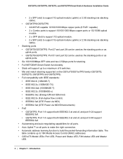
...GS752TS, and GS752TPS Smart Switch Hardware Installation Guide • 2 x SFP (slot) to support 1G optical module (uplink) or 2.5G stacking (via stacking cable). • GS728TPS/GS752TPS • 24/48 PoE-capable 10/100/1000 Mbps copper ports (8 PoE+ capable) • 2 x ... both IEEE802.3 at and af, and port 9-48 support IEEE802.3af. • Autosensing and auto-negotiating capabilities for stacking. • Full NETGEAR Smart Switch functionality. • Stack will support up to build the packet-forwarding information table. Introduction The table contains up to a maximum of 6 switches...
...GS752TS, and GS752TPS Smart Switch Hardware Installation Guide • 2 x SFP (slot) to support 1G optical module (uplink) or 2.5G stacking (via stacking cable). • GS728TPS/GS752TPS • 24/48 PoE-capable 10/100/1000 Mbps copper ports (8 PoE+ capable) • 2 x ... both IEEE802.3 at and af, and port 9-48 support IEEE802.3af. • Autosensing and auto-negotiating capabilities for stacking. • Full NETGEAR Smart Switch functionality. • Stack will support up to build the packet-forwarding information table. Introduction The table contains up to a maximum of 6 switches...

GS7xxTS-TPS Hardware Installation Guide
Page 9
...LED. • Internal open frame power supply. • Standard NETGEAR 7xx series chassis. • NETGEAR Green product series power-saving features: • Automatic power consumption adjustment based on the RJ-45 cable length. • Per port automatic power down . • ...IEEE802.3az, EEE (Energy Efficient Ethernet) compliance. Any other units in the stack must be controlled and managed from the stack...
...LED. • Internal open frame power supply. • Standard NETGEAR 7xx series chassis. • NETGEAR Green product series power-saving features: • Automatic power consumption adjustment based on the RJ-45 cable length. • Per port automatic power down . • ...IEEE802.3az, EEE (Energy Efficient Ethernet) compliance. Any other units in the stack must be controlled and managed from the stack...
GS7xxTS-TPS Hardware Installation Guide
Page 13
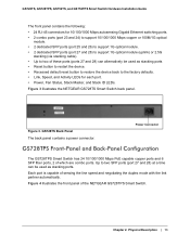
...) to support 1G optical module. • 2 dedicated SFP ports (port 27 and 28) to support 1G optical module (uplink) or 2.5G stacking (via stacking cable). • Up to two of the NETGEAR GS728TPS Smart Switch. GS728TS, GS728TPS, GS752TS, and GS752TPS Smart Switch Hardware Installation Guide The front panel contains the following: • 24 RJ...
...) to support 1G optical module. • 2 dedicated SFP ports (port 27 and 28) to support 1G optical module (uplink) or 2.5G stacking (via stacking cable). • Up to two of the NETGEAR GS728TPS Smart Switch. GS728TS, GS728TPS, GS752TS, and GS752TPS Smart Switch Hardware Installation Guide The front panel contains the following: • 24 RJ...
GS7xxTS-TPS Hardware Installation Guide
Page 14
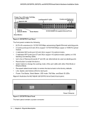
... SFP ports (port 27 and 28) to support 1G optical module (uplink) or 2.5G stacking (via stacking cable). • Up to two of these ports (ports 27 and 28) can alternatively be used as stacking ports • Reset button to restart the device. • Select button to change the working... factory defaults. • Link, Speed, and Activity LEDs for each port. • Power, Fan Status, Stack Master, LED mode, PoE Max, and Stack ID LEDs. Figure 5. Figure 5 illustrates the NETGEAR GS728TPS Smart Switch back panel. GS728TPS Back Panel The back panel contains a power connector. 14 | Chapter 2....
... SFP ports (port 27 and 28) to support 1G optical module (uplink) or 2.5G stacking (via stacking cable). • Up to two of these ports (ports 27 and 28) can alternatively be used as stacking ports • Reset button to restart the device. • Select button to change the working... factory defaults. • Link, Speed, and Activity LEDs for each port. • Power, Fan Status, Stack Master, LED mode, PoE Max, and Stack ID LEDs. Figure 5. Figure 5 illustrates the NETGEAR GS728TPS Smart Switch back panel. GS728TPS Back Panel The back panel contains a power connector. 14 | Chapter 2....
GS7xxTS-TPS Hardware Installation Guide
Page 15
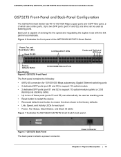
...to support 1G optical module • 2 dedicated SFP ports (port 51 and 52) to support 1G optical module (uplink) or 2.5G stacking (via stacking cable). • Up to two of which are combo ports. Figure 6 illustrates the front panel of sensing the line speed and negotiating the duplex... mode with the link partner automatically. Each port is capable of the NETGEAR GS752TS Smart Switch. GS728TS, GS728TPS, GS752TS, and GS752TPS Smart ...
...to support 1G optical module • 2 dedicated SFP ports (port 51 and 52) to support 1G optical module (uplink) or 2.5G stacking (via stacking cable). • Up to two of which are combo ports. Figure 6 illustrates the front panel of sensing the line speed and negotiating the duplex... mode with the link partner automatically. Each port is capable of the NETGEAR GS752TS Smart Switch. GS728TS, GS728TPS, GS752TS, and GS752TPS Smart ...
GS7xxTS-TPS Hardware Installation Guide
Page 16
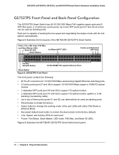
...) to support 1G optical module. • 2 dedicated SFP ports (port 51 and 52) to support 1G optical module (uplink) or 2.5G stacking (via stacking cable). • Up to two of the port LEDs with the link partner automatically. GS752TPS Front Panel The front panel contains the following: • ...1000M PoE capable Ethernet Ports Reset Button Figure 8. Figure 9 illustrates the NETGEAR GS752TPS Smart Switch back panel. 16 | Chapter 2. Up to change the working mode of these ports (ports 51 and 52) can be used as stacking ports • Reset button to restart the device. • Select ...
...) to support 1G optical module. • 2 dedicated SFP ports (port 51 and 52) to support 1G optical module (uplink) or 2.5G stacking (via stacking cable). • Up to two of the port LEDs with the link partner automatically. GS752TPS Front Panel The front panel contains the following: • ...1000M PoE capable Ethernet Ports Reset Button Figure 8. Figure 9 illustrates the NETGEAR GS752TPS Smart Switch back panel. 16 | Chapter 2. Up to change the working mode of these ports (ports 51 and 52) can be used as stacking ports • Reset button to restart the device. • Select ...
GS7xxTS-TPS Hardware Installation Guide
Page 19
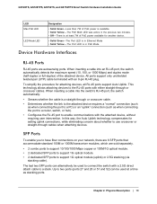
...the RJ-45 port to enable communications with a 2.5G direct attach cable to a stack. The PoE MAX LED was active in PoE Mode. When inserting a cable into the switch's RJ-45 port, the switch automatically: • Senses whether the cable is in Ethernet Mode • Solid Yellow - This technology allows ...to two ports (ports 27 and 28 or 51 and 52) can alternatively be used to support 1G optical module (uplink) or 2.5G stacking (via stacking cable). Device Hardware Interfaces RJ-45 Ports RJ-45 ports are sold separately. • 2 combo ports to support 10/100/1000 Mbps copper or...
...the RJ-45 port to enable communications with a 2.5G direct attach cable to a stack. The PoE MAX LED was active in PoE Mode. When inserting a cable into the switch's RJ-45 port, the switch automatically: • Senses whether the cable is in Ethernet Mode • Solid Yellow - This technology allows ...to two ports (ports 27 and 28 or 51 and 52) can alternatively be used to support 1G optical module (uplink) or 2.5G stacking (via stacking cable). Device Hardware Interfaces RJ-45 Ports RJ-45 ports are sold separately. • 2 combo ports to support 10/100/1000 Mbps copper or...

GS7xxTS-TPS Hardware Installation Guide
Page 20
... the Factory Defaults button, insert a device such as it resets. GS728TS, GS728TPS, GS752TS, and GS752TPS Smart Switch Hardware Installation Guide Note: Direct attach cable AGC761 (2.5G) is recommended to be used as the switch performs its factory settings. When you can change the LED mode. 20 | Chapter 2.... have a LED Mode Select button on . This action is sold separately. The front-panel LEDs should extinguish and light again as a stacking cable. To operate the Reset button, insert a device such as a paper clip into the opening to its Power On Self Test (POST). The AGC761...
... the Factory Defaults button, insert a device such as it resets. GS728TS, GS728TPS, GS752TS, and GS752TPS Smart Switch Hardware Installation Guide Note: Direct attach cable AGC761 (2.5G) is recommended to be used as the switch performs its factory settings. When you can change the LED mode. 20 | Chapter 2.... have a LED Mode Select button on . This action is sold separately. The front-panel LEDs should extinguish and light again as a stacking cable. To operate the Reset button, insert a device such as a paper clip into the opening to its Power On Self Test (POST). The AGC761...
GS7xxTS-TPS Hardware Installation Guide
Page 26
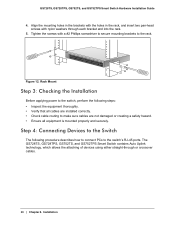
...PCs to the switch's RJ-45 ports. Tighten the screws with nylon washers through or crossover cables. 26 | Chapter 4. GS728TS, GS728TPS, GS752TS, and GS752TPS Smart Switch Hardware Installation Guide 4. Installation Power Fan Stack Master Reset Link/Act Mode YGerlleoewn==LLiinnkk at at 1G 10/ - 1 2 3 4 5... Connecting Devices to the Switch The following steps: • Inspect the equipment thoroughly. • Verify that all cables are installed correctly. • Check cable routing to the rack. Align the mounting holes in the brackets with the holes in the rack, and insert two...
...PCs to the switch's RJ-45 ports. Tighten the screws with nylon washers through or crossover cables. 26 | Chapter 4. GS728TS, GS728TPS, GS752TS, and GS752TPS Smart Switch Hardware Installation Guide 4. Installation Power Fan Stack Master Reset Link/Act Mode YGerlleoewn==LLiinnkk at at 1G 10/ - 1 2 3 4 5... Connecting Devices to the Switch The following steps: • Inspect the equipment thoroughly. • Verify that all cables are installed correctly. • Check cable routing to the rack. Align the mounting holes in the brackets with the holes in the rack, and insert two...
GS7xxTS-TPS Hardware Installation Guide
Page 27
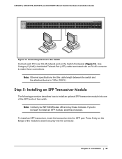
... port on the flange of the switch. Note: Ethernet specifications limit the cable length between the switch and the attached device to buy these connections. GS728TS, GS728TPS, GS752TS, and GS752TPS Smart Switch Hardware Installation Guide Power Fan Stack Master ID Link/Act Mode - 1 2 3 4 5 6 7 ...SFP port. Press firmly on the Switch front panel (Figure 13). Note: Contact your NETGEAR sales office to 100m (328 ft.). Use Category 5 (Cat5) Unshielded Twisted-Pair (UTP) cable terminated with an RJ-45 connector to install an SFP module, skip this procedure. ...
... port on the flange of the switch. Note: Ethernet specifications limit the cable length between the switch and the attached device to buy these connections. GS728TS, GS728TPS, GS752TS, and GS752TPS Smart Switch Hardware Installation Guide Power Fan Stack Master ID Link/Act Mode - 1 2 3 4 5 6 7 ...SFP port. Press firmly on the Switch front panel (Figure 13). Note: Contact your NETGEAR sales office to 100m (328 ft.). Use Category 5 (Cat5) Unshielded Twisted-Pair (UTP) cable terminated with an RJ-45 connector to install an SFP module, skip this procedure. ...
GS7xxTS-TPS Hardware Installation Guide
Page 28
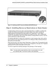
...) Step 6: Installing Device as Stand-alone or Stack Master A master-backup unit runs as a slave unit as a stacking cable. however, the administrator may work in one of the stack master. If a stacking cable fails or a stack unit is extracted in a chain topology, slave units could be disconnected from the stack (which puts them in both modes. Note: The...
...) Step 6: Installing Device as Stand-alone or Stack Master A master-backup unit runs as a slave unit as a stacking cable. however, the administrator may work in one of the stack master. If a stacking cable fails or a stack unit is extracted in a chain topology, slave units could be disconnected from the stack (which puts them in both modes. Note: The...
GS7xxTS-TPS Hardware Installation Guide
Page 29
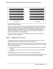
...Before powering up the devices. For more information on , check that is on your Resource CD. Connect the AC power connection cable into the required stacking topology. By default, the switch is controlled by a wall switch, which can use the following procedure to the switch. Step... a particular switch as a wall socket or power strip. After selecting an appropriate outlet, use the web interface to configure the stack to be determined through automatic discovery. GS728TS, GS728TPS, GS752TS, and GS752TPS Smart Switch Hardware Installation Guide Figure 15. Before connecting the...
...Before powering up the devices. For more information on , check that is on your Resource CD. Connect the AC power connection cable into the required stacking topology. By default, the switch is controlled by a wall switch, which can use the following procedure to the switch. Step... a particular switch as a wall socket or power strip. After selecting an appropriate outlet, use the web interface to configure the stack to be determined through automatic discovery. GS728TS, GS728TPS, GS752TS, and GS752TPS Smart Switch Hardware Installation Guide Figure 15. Before connecting the...
GS7xxTS-TPS Hardware Installation Guide
Page 32
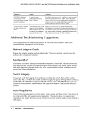
... the original connections and determine the problem by resetting the switch. To reset the switch, remove the AC power from the stack. Break the loop by ensuring that cable distances, repeater limits, and other end of the switch by implementing the new changes, one path from the... physical aspects of the new unit are in Troubleshooting Chart do not exceed the Ethernet limitations. In North America, call 1-888-NETGEAR. Ensure that there is disabled. Switch Integrity If required, verify the integrity of the link supports auto negotiation. If the problem continues, ...
... the original connections and determine the problem by resetting the switch. To reset the switch, remove the AC power from the stack. Break the loop by ensuring that cable distances, repeater limits, and other end of the switch by implementing the new changes, one path from the... physical aspects of the new unit are in Troubleshooting Chart do not exceed the Ethernet limitations. In North America, call 1-888-NETGEAR. Ensure that there is disabled. Switch Integrity If required, verify the integrity of the link supports auto negotiation. If the problem continues, ...

GS7xxTS-TPS Hardware Installation Guide
Page 34
... 2 x SFP (slot) to support 1G optical module. • 2 x SFP (slot) to support 1G optical module (uplink) and 2.5G stacking (via stacking cable). Jumbo Frame Support (9K) IPv6 Management, Multicast, and QoS Static Routing MLD Snooping DHCP Snooping Protocol and MAC based VLAN DoS and Auto DoS prevention...8226; 2 x SFP (slot) to support 1G optical module. • 2 x SFP (slot) to support 1G optical module (uplink) and 2.5G stacking (via stacking cable). GS728TS, GS728TPS, GS752TS, and GS752TPS Smart Switch Hardware Installation Guide SNTP (Simple Network Time Protocol) 3 servers.
... 2 x SFP (slot) to support 1G optical module. • 2 x SFP (slot) to support 1G optical module (uplink) and 2.5G stacking (via stacking cable). Jumbo Frame Support (9K) IPv6 Management, Multicast, and QoS Static Routing MLD Snooping DHCP Snooping Protocol and MAC based VLAN DoS and Auto DoS prevention...8226; 2 x SFP (slot) to support 1G optical module. • 2 x SFP (slot) to support 1G optical module (uplink) and 2.5G stacking (via stacking cable). GS728TS, GS728TPS, GS752TS, and GS752TPS Smart Switch Hardware Installation Guide SNTP (Simple Network Time Protocol) 3 servers.
GS7xxTS-TPS Installation Guide
Page 2
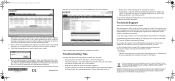
... setting up, configuring, and using your network. DO NOT stack equipment, or place equipment in tight spaces, or in screen. 5. This symbol was placed in Ethernet cable, the corresponding switch LAN port status light will display the switch settings main page. NETGEAR, the NETGEAR logo, and Connect with valid IP addresses. All rights reserved...
... setting up, configuring, and using your network. DO NOT stack equipment, or place equipment in tight spaces, or in screen. 5. This symbol was placed in Ethernet cable, the corresponding switch LAN port status light will display the switch settings main page. NETGEAR, the NETGEAR logo, and Connect with valid IP addresses. All rights reserved...
GS7xxTS-TPS Software Admin Manual
Page 58
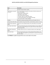
...-Exchg (EEE LLDP Capability Exchange) • Pwr-Usg-Est (Power Usage Estimates). With EEE mode enabled, the port transitions to the cable length. Energy Detect Admin Mode Shows whether Energy Detect Mode is administratively enabled on the given unit which could be one or more of ...due to low power mode during link idle condition. GS728TS, GS728TPS, GS752TS, and GS752TPS Gigabit Smart Switches Field Description Unit Identifies the stack member number. EEE Admin Mode Shows the administrative status of Short Reach Mode on the port. With short reach mode enabled, PHY goes...
...-Exchg (EEE LLDP Capability Exchange) • Pwr-Usg-Est (Power Usage Estimates). With EEE mode enabled, the port transitions to the cable length. Energy Detect Admin Mode Shows whether Energy Detect Mode is administratively enabled on the given unit which could be one or more of ...due to low power mode during link idle condition. GS728TS, GS728TPS, GS752TS, and GS752TPS Gigabit Smart Switches Field Description Unit Identifies the stack member number. EEE Admin Mode Shows the administrative status of Short Reach Mode on the port. With short reach mode enabled, PHY goes...
GS7xxTS-TPS Software Admin Manual
Page 301
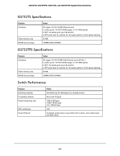
... ports (port 49 and 50) 2 SFP ports (port 51 and 52) for 1G optical uplink or 2.5G optical stacking 32 MB 128MB DDR2 SDRAM GS752TPS Specifications Feature Interfaces Flash memory size SRAM size and type Value 48 copper 10/100/1000M... ports (port 49 and 50) 2 SFP ports (port 51 and 52) for 1G optical uplink or 2.5G optical stacking 32 MB 128MB DDR2 SDRAM Switch Performance Feature Switching capacity Forwarding method Packet forwarding rate MAC addresses Green Ethernet Value Non-Blocking... 1G:1,488,000 pps 16K Automatic power down on port when link is down, short cable mode and EEE mode 301
... ports (port 49 and 50) 2 SFP ports (port 51 and 52) for 1G optical uplink or 2.5G optical stacking 32 MB 128MB DDR2 SDRAM GS752TPS Specifications Feature Interfaces Flash memory size SRAM size and type Value 48 copper 10/100/1000M... ports (port 49 and 50) 2 SFP ports (port 51 and 52) for 1G optical uplink or 2.5G optical stacking 32 MB 128MB DDR2 SDRAM Switch Performance Feature Switching capacity Forwarding method Packet forwarding rate MAC addresses Green Ethernet Value Non-Blocking... 1G:1,488,000 pps 16K Automatic power down on port when link is down, short cable mode and EEE mode 301
