
Installation Guide
Page 14
...; Status of the hub power supply • Collision occurrence on an Ethernet segment in a standalone hub or a stack of hubs • Data utilization percentage of the Ethernet segment in a standalone hub or a stack of the hub and two on each port 5 = Normal/Uplink push button Figure 2-2. Front panel of the Model FE108 Fast Ethernet Hub 185EA LED Display Three...
...; Status of the hub power supply • Collision occurrence on an Ethernet segment in a standalone hub or a stack of hubs • Data utilization percentage of the Ethernet segment in a standalone hub or a stack of the hub and two on each port 5 = Normal/Uplink push button Figure 2-2. Front panel of the Model FE108 Fast Ethernet Hub 185EA LED Display Three...

Installation Guide
Page 15
... Mbps operation requires the use of the Model FE104 hub provides four RJ-45 100BASE-TX ports, and the Model FE108 provides eight RJ-45 100BASE-TX ports. Table B-1...Hubs Table 2-1 describes each LED on the port. Note that occasional collisions are in Appendix B, "RJ-45 Connector Information." RJ-45 100BASE-TX Ports The front panel of Category 5 UTP cable with a 100 Mbps certified connector. There is supplied... Green On Description Power is data collision on cabling. Four LEDs indicate whether the percentage of data utilization on the hub or stack of hubs is being partitioned ...
... Mbps operation requires the use of the Model FE104 hub provides four RJ-45 100BASE-TX ports, and the Model FE108 provides eight RJ-45 100BASE-TX ports. Table B-1...Hubs Table 2-1 describes each LED on the port. Note that occasional collisions are in Appendix B, "RJ-45 Connector Information." RJ-45 100BASE-TX Ports The front panel of Category 5 UTP cable with a 100 Mbps certified connector. There is supplied... Green On Description Power is data collision on cabling. Four LEDs indicate whether the percentage of data utilization on the hub or stack of hubs is being partitioned ...
Installation Guide
Page 17
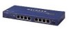
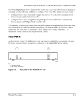
Rear Panel As illustrated in Figure 2-5 and Figure 2-6, the rear panel of each hub has a grounding clip and a DC power receptacle that is to be connected to a normal-wired device, such as a network station or a PC. • Configure Ports 4 and...for the Model FE104 and Model FE108 Fast Ethernet Hubs The Normal/Uplink push button eliminates the need to Appendix C, "Fast Ethernet and Cabling Guidelines," for information on the hubs cannot be connected to the supplied DC power adapter. 1 2 12 Vdc 1.2A -+ Key: 1 = Grounding clip 2 = DC power receptacle Figure 2-5. Use the following ...
Rear Panel As illustrated in Figure 2-5 and Figure 2-6, the rear panel of each hub has a grounding clip and a DC power receptacle that is to be connected to a normal-wired device, such as a network station or a PC. • Configure Ports 4 and...for the Model FE104 and Model FE108 Fast Ethernet Hubs The Normal/Uplink push button eliminates the need to Appendix C, "Fast Ethernet and Cabling Guidelines," for information on the hubs cannot be connected to the supplied DC power adapter. 1 2 12 Vdc 1.2A -+ Key: 1 = Grounding clip 2 = DC power receptacle Figure 2-5. Use the following ...


