Installation Guide
Page 5
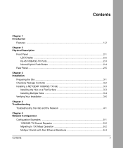
... Description Front Panel ...2-1 LED Display ...2-2 RJ-45 100BASE-TX Ports 2-3 Normal/Uplink Push Button 2-4 Rear Panel ...2-5 Chapter 3 Installation Preparing the Site ...3-1 Checking Package Contents 3-2 Installing a NETGEAR 100BASE-TX Hub 3-3 Installing the Hub on a Flat Surface 3-3 Installing Multiple Hubs 3-4 Verifying Your Installation 3-6 Chapter 4 Troubleshooting Troubleshooting the Hub and the Network 4-1 Chapter 5 Network Configuration Configuration...
... Description Front Panel ...2-1 LED Display ...2-2 RJ-45 100BASE-TX Ports 2-3 Normal/Uplink Push Button 2-4 Rear Panel ...2-5 Chapter 3 Installation Preparing the Site ...3-1 Checking Package Contents 3-2 Installing a NETGEAR 100BASE-TX Hub 3-3 Installing the Hub on a Flat Surface 3-3 Installing Multiple Hubs 3-4 Verifying Your Installation 3-6 Chapter 4 Troubleshooting Troubleshooting the Hub and the Network 4-1 Chapter 5 Network Configuration Configuration...
Installation Guide
Page 7
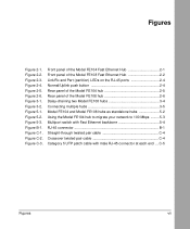
.../Rx and Part (partition) LEDs on the RJ-45 ports 2-4 Normal/Uplink push button 2-4 Rear panel of the Model FE104 hub 2-5 Rear panel of the Model FE108 hub 2-6 Daisy-chaining two Model FE108 hubs 3-4 Connecting multiple hubs 3-5 Model FE104 and Model FE108 hubs as standalone hubs 5-2 Using the Model FE104 hub to migrate your network to 100 Mbps .........5-3 Multiport switch with Fast...
.../Rx and Part (partition) LEDs on the RJ-45 ports 2-4 Normal/Uplink push button 2-4 Rear panel of the Model FE104 hub 2-5 Rear panel of the Model FE108 hub 2-6 Daisy-chaining two Model FE108 hubs 3-4 Connecting multiple hubs 3-5 Model FE104 and Model FE108 hubs as standalone hubs 5-2 Using the Model FE104 hub to migrate your network to 100 Mbps .........5-3 Multiport switch with Fast...

Installation Guide
Page 12
... metal case design enables easy tabletop or under-desk installation. 1-2 Introduction Normal/Uplink push button to clearly indicate the status of each port. - Installation Guide for the Model FE104 and Model FE108 Fast Ethernet Hubs Features The Model FE104 and Model FE108 hubs have the following key features: • IEEE 802.3u standard compliance allows interoperation...
... metal case design enables easy tabletop or under-desk installation. 1-2 Introduction Normal/Uplink push button to clearly indicate the status of each port. - Installation Guide for the Model FE104 and Model FE108 Fast Ethernet Hubs Features The Model FE104 and Model FE108 hubs have the following key features: • IEEE 802.3u standard compliance allows interoperation...
Installation Guide
Page 13
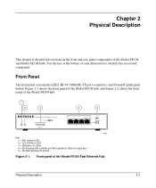
Use the key at the bottom of the Model FE104 Fast Ethernet Hub Physical Description 2-1 Front panel of each port 5 = Normal/Uplink push button 186EA Figure 2-1. Figure 2-1 shows the front panel of the Model FE104 hub, and Figure 2-2 shows the front panel of the Model FE104 and Model FE108 hubs. Chapter 2 Physical Description This chapter is divided into sections...
Use the key at the bottom of the Model FE104 Fast Ethernet Hub Physical Description 2-1 Front panel of each port 5 = Normal/Uplink push button 186EA Figure 2-1. Figure 2-1 shows the front panel of the Model FE104 hub, and Figure 2-2 shows the front panel of the Model FE104 and Model FE108 hubs. Chapter 2 Physical Description This chapter is divided into sections...

Installation Guide
Page 14
Installation Guide for all ports in the hub • Partition status for the Model FE104 and Model FE108 Fast Ethernet Hubs 1 2 3 4 5 Pwr Col 100BASE-TX FAST ETHERNET HUB FE108 100 Mbps F AST 1 10 20 >30 Utilization % 1 2 3 4 Link/Rx Part Normal/Uplink 5 6 6 8 Key: 1 = Pwr (power) LED 2 = Col (collision)... a standalone hub or a stack of hubs • Data utilization percentage of the Ethernet segment in a standalone hub or a stack of the hub and two on each port 5 = Normal/Uplink push button Figure 2-2. Front panel of the Model FE108 Fast Ethernet Hub 185EA LED ...
Installation Guide for all ports in the hub • Partition status for the Model FE104 and Model FE108 Fast Ethernet Hubs 1 2 3 4 5 Pwr Col 100BASE-TX FAST ETHERNET HUB FE108 100 Mbps F AST 1 10 20 >30 Utilization % 1 2 3 4 Link/Rx Part Normal/Uplink 5 6 6 8 Key: 1 = Pwr (power) LED 2 = Col (collision)... a standalone hub or a stack of hubs • Data utilization percentage of the Ethernet segment in a standalone hub or a stack of the hub and two on each port 5 = Normal/Uplink push button Figure 2-2. Front panel of the Model FE108 Fast Ethernet Hub 185EA LED ...

Installation Guide
Page 16
...(partition) LEDs on the RJ-45 ports Normal/Uplink Push Button The Normal/Uplink push button on the Model FE108 hub. When the push button is pressed in Figure 2-4, allows you to select uplink (MDI) or normal (MDI-X) wiring for Port 4 on the Model FE104 hub and Port 8 on the front panel of each... RJ-45 connector. Link/Rx Part 184EA Figure 2-3. Both LEDs are described in Figure 2-3, two LEDs are configured for normal wiring when the push button is the Part (partition) LED. Normal/Uplink push button Model FE108 ...
...(partition) LEDs on the RJ-45 ports Normal/Uplink Push Button The Normal/Uplink push button on the Model FE108 hub. When the push button is pressed in Figure 2-4, allows you to select uplink (MDI) or normal (MDI-X) wiring for Port 4 on the Model FE104 hub and Port 8 on the front panel of each... RJ-45 connector. Link/Rx Part 184EA Figure 2-3. Both LEDs are described in Figure 2-3, two LEDs are configured for normal wiring when the push button is the Part (partition) LED. Normal/Uplink push button Model FE108 ...
Installation Guide
Page 17
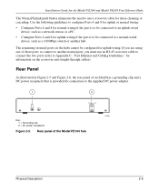
...100 Mbps switch or another normal port, you are using one of these ports to connect to another hub. Installation Guide for the Model FE104 and Model FE108 Fast Ethernet Hubs The Normal/Uplink push button eliminates the need to a normal-wired device, such as a network station or a PC. •... Configure Ports 4 and 8 for uplink wiring if the port is provided for connection to Appendix C, "Fast Ethernet...
...100 Mbps switch or another normal port, you are using one of these ports to connect to another hub. Installation Guide for the Model FE104 and Model FE108 Fast Ethernet Hubs The Normal/Uplink push button eliminates the need to a normal-wired device, such as a network station or a PC. •... Configure Ports 4 and 8 for uplink wiring if the port is provided for connection to Appendix C, "Fast Ethernet...

Installation Guide
Page 22
... you with 100 Mbps connection Figure 3-1. Installation Guide for the Model FE104 and Model FE108 Fast Ethernet Hubs Installing Multiple Hubs This section provides you have installed your hubs using one of the methods shown, connect the power adapter to the...FE108 hubs 3-4 Installation In Figure 3-2, multiple hubs are connected to "Verifying Your Installation." 1 2 Model FE108 hub Model FE108 hub 3 359EA Key: 1 = Model FE108 Fast Ethernet Hub (Normal/Uplink push button set in Uplink position) 2 = Model FE108 Fast Ethernet Hub (Normal/Uplink push button set in Figure 3-1, two hubs ...
... you with 100 Mbps connection Figure 3-1. Installation Guide for the Model FE104 and Model FE108 Fast Ethernet Hubs Installing Multiple Hubs This section provides you have installed your hubs using one of the methods shown, connect the power adapter to the...FE108 hubs 3-4 Installation In Figure 3-2, multiple hubs are connected to "Verifying Your Installation." 1 2 Model FE108 hub Model FE108 hub 3 359EA Key: 1 = Model FE108 Fast Ethernet Hub (Normal/Uplink push button set in Uplink position) 2 = Model FE108 Fast Ethernet Hub (Normal/Uplink push button set in Figure 3-1, two hubs ...

Installation Guide
Page 23
... switch Model FE104 hub Model FE108 hub 5 Model EN108 hub 5 6 7 8 9 199EA Key: 1 = 100 Mbps connection 2 = Server 3 = FS104 10/100 Mbps switch (Normal/Uplink push button set in Normal position) 4 = 10 Mbps connection 5 = PCs with 100 Mbps connection to Fast Ethernet hub 6 = PCs with 10 Mbps connection to Ethernet hub 7 = Model FE104 Fast Ethernet Hub (Normal/Uplink push button set in Uplink position) 8 = Model...
... switch Model FE104 hub Model FE108 hub 5 Model EN108 hub 5 6 7 8 9 199EA Key: 1 = 100 Mbps connection 2 = Server 3 = FS104 10/100 Mbps switch (Normal/Uplink push button set in Normal position) 4 = 10 Mbps connection 5 = PCs with 100 Mbps connection to Fast Ethernet hub 6 = PCs with 10 Mbps connection to Ethernet hub 7 = Model FE104 Fast Ethernet Hub (Normal/Uplink push button set in Uplink position) 8 = Model...
Installation Guide
Page 26
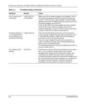
... the PC is installed, and check for the Model FE104 and Model FE108 Fast Ethernet Hubs Table 4-1. If you are on Check Make sure that the proper cable is in the Normal position. Collisions are other MDI-wired device, make sure the Normal/Uplink push button is set in the PC. Installation Guide for...
... the PC is installed, and check for the Model FE104 and Model FE108 Fast Ethernet Hubs Table 4-1. If you are on Check Make sure that the proper cable is in the Normal position. Collisions are other MDI-wired device, make sure the Normal/Uplink push button is set in the PC. Installation Guide for...

Installation Guide
Page 28
... connection 3 = Model FE104 Fast Ethernet Hub or Model FE108 Fast Ethernet Hub (Normal/Uplink push button set in Normal position on both hubs) 4 = Server 188EA Figure 5-1. When many local area network (LAN) environments, the primary problem is access to 100 Mbps Operation One of the more frequently, resulting in low data throughput. By adding a NETGEAR Model SW502...
... connection 3 = Model FE104 Fast Ethernet Hub or Model FE108 Fast Ethernet Hub (Normal/Uplink push button set in Normal position on both hubs) 4 = Server 188EA Figure 5-1. When many local area network (LAN) environments, the primary problem is access to 100 Mbps Operation One of the more frequently, resulting in low data throughput. By adding a NETGEAR Model SW502...

Installation Guide
Page 29
Using the Model FE104 hub to migrate your network to Model EN516 Ethernet Hub.) 6 = 10 Mbps connection 7 = Model EN516 Ethernet Hub (Normal/Uplink push button set in Normal position on port connected to Model FE104 Fast Ethernet Hub (Normal/Uplink push button set in Uplink position) 8 = PCs with 100 Mbps connections 2 = 100 Mbps connection 3 = Model FE104 Fast Ethernet Hub (Normal/Uplink push button set in Normal...
Using the Model FE104 hub to migrate your network to Model EN516 Ethernet Hub.) 6 = 10 Mbps connection 7 = Model EN516 Ethernet Hub (Normal/Uplink push button set in Normal position on port connected to Model FE104 Fast Ethernet Hub (Normal/Uplink push button set in Uplink position) 8 = PCs with 100 Mbps connections 2 = 100 Mbps connection 3 = Model FE104 Fast Ethernet Hub (Normal/Uplink push button set in Normal...

Installation Guide
Page 30
... Mbps connection 3 = Model FE108 Fast Ethernet Hub (Normal/Uplink push button set in Normal position) 4 = Server 5 = Model SW507 switch (Normal/Uplink push button set in Uplink position) 6 = 10 Mbps connection 7 = Model EN516 Ethernet Hubs (Normal/Uplink push button set in Uplink position) Figure 5-3. Installation Guide for the Model FE104 and Model FE108 Fast Ethernet Hubs Multiport Switch with Fast Ethernet Backbone If...
... Mbps connection 3 = Model FE108 Fast Ethernet Hub (Normal/Uplink push button set in Normal position) 4 = Server 5 = Model SW507 switch (Normal/Uplink push button set in Uplink position) 6 = 10 Mbps connection 7 = Model EN516 Ethernet Hubs (Normal/Uplink push button set in Uplink position) Figure 5-3. Installation Guide for the Model FE104 and Model FE108 Fast Ethernet Hubs Multiport Switch with Fast Ethernet Backbone If...

Installation Guide
Page 34
Input Receive Data - Pin 1 2 3 6 4, 5, 7, 8 RJ-45 connector pinouts Normal (MDI-X) Uplink (MDI) * Input Receive Data + Output Transmit Data + Input Receive Data - Output Transmit Data - Output Transmit Data + Input Receive Data + Output Transmit Data - B-2 RJ-45 Connector Information Installation Guide for data transmission * Applicable to Port 4 on the Model FE104 hub and Port 8 on the Model FE108 hub, when the Normal/Uplink push button is in the Uplink position. Internal termination, not used for the Model FE104 and Model FE108 Fast Ethernet Hubs Table B-1.
Input Receive Data - Pin 1 2 3 6 4, 5, 7, 8 RJ-45 connector pinouts Normal (MDI-X) Uplink (MDI) * Input Receive Data + Output Transmit Data + Input Receive Data - Output Transmit Data - Output Transmit Data + Input Receive Data + Output Transmit Data - B-2 RJ-45 Connector Information Installation Guide for data transmission * Applicable to Port 4 on the Model FE104 hub and Port 8 on the Model FE108 hub, when the Normal/Uplink push button is in the Uplink position. Internal termination, not used for the Model FE104 and Model FE108 Fast Ethernet Hubs Table B-1.

Installation Guide
Page 42
... migration to 100 Mbps 1-1, 5-2 multiple hub installation 3-4 N network adapter cards, troubleshooting 4-2 normal wiring 2-4, 2-5, 4-2, C-4 Normal/Uplink push button 1-2, 2-1, 2-2, 2-4, 4-2 O operating conditions 3-1 P package contents 3-2... C-2 humidity 3-1 operating conditions 3-1 power 3-1 temperature 3-1 ventilation 3-1 wiring 3-1 RJ-45 connector pinouts (table) B-2 troubleshooting 4-1 using for the Model FE104 and Model FE108 Fast Ethernet Hubs L LEDs Col (collision) 2-3, 4-2 description (table) 2-3 Link/Rx 2-3, 2-4, 3-6 Link/Rx, troubleshooting 4-2 overview 1-2 Part (partition) 2-3, 2-4...
... migration to 100 Mbps 1-1, 5-2 multiple hub installation 3-4 N network adapter cards, troubleshooting 4-2 normal wiring 2-4, 2-5, 4-2, C-4 Normal/Uplink push button 1-2, 2-1, 2-2, 2-4, 4-2 O operating conditions 3-1 P package contents 3-2... C-2 humidity 3-1 operating conditions 3-1 power 3-1 temperature 3-1 ventilation 3-1 wiring 3-1 RJ-45 connector pinouts (table) B-2 troubleshooting 4-1 using for the Model FE104 and Model FE108 Fast Ethernet Hubs L LEDs Col (collision) 2-3, 4-2 description (table) 2-3 Link/Rx 2-3, 2-4, 3-6 Link/Rx, troubleshooting 4-2 overview 1-2 Part (partition) 2-3, 2-4...

Installation Guide
Page 43
... Wide Web iii Index 3 Installation Guide for the Model FE104 and Model FE108 Fast Ethernet Hubs S site preparation 3-1 straight-through cable 2-5, 4-2 T technical specifications A-1 temperature requirements 3-1 troubleshooting COL LED blinking 4-2 Link/Rx LED intermittent 4-1 Link/Rx LED off 4-1, 4-2 network adapter cards 4-2 Normal/Uplink push button 4-2 Port 4 4-2 Port 8 4-2 port connection 4-1, 4-2 Pwr LED off 4-1 RJ...
... Wide Web iii Index 3 Installation Guide for the Model FE104 and Model FE108 Fast Ethernet Hubs S site preparation 3-1 straight-through cable 2-5, 4-2 T technical specifications A-1 temperature requirements 3-1 troubleshooting COL LED blinking 4-2 Link/Rx LED intermittent 4-1 Link/Rx LED off 4-1, 4-2 network adapter cards 4-2 Normal/Uplink push button 4-2 Port 4 4-2 Port 8 4-2 port connection 4-1, 4-2 Pwr LED off 4-1 RJ...


