EN104TP Installation Guide
Page 2
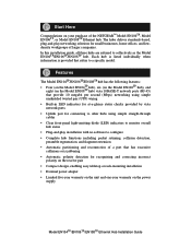
...on the Model EN104TP hub), six (on the Model EN106TP hub), and eight (on the Model EN108TP hub) vista 10BASE-T network ports (RJ-45) ...status checks provided by vista network ports • Uplink port for connecting to other hubs using simple straight-through cables • Clear...Model EN104TP/EN106TP/EN108TP Ethernet Hub Installation Guide In this installation guide, all three hubs are referred to a specific model. The hubs deliver... of a port that has excessive collisions or is provided that refers to collectively as the Model EN104TP/EN106TP/EN108TP hub. Each hub is listed individually...
...on the Model EN104TP hub), six (on the Model EN106TP hub), and eight (on the Model EN108TP hub) vista 10BASE-T network ports (RJ-45) ...status checks provided by vista network ports • Uplink port for connecting to other hubs using simple straight-through cables • Clear...Model EN104TP/EN106TP/EN108TP Ethernet Hub Installation Guide In this installation guide, all three hubs are referred to a specific model. The hubs deliver... of a port that has excessive collisions or is provided that refers to collectively as the Model EN104TP/EN106TP/EN108TP hub. Each hub is listed individually...
EN104TP Installation Guide
Page 4
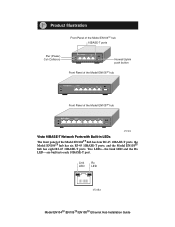
...-the Link LED and the Rx LED-are built into each 10BASE-T port. Link Rx LED LED 8724EA Model EN104TP/EN106TP/EN108TP Ethernet Hub Installation Guide Product Illustration Front Panel of the Model EN104TP hub 10BASE-T ports Pwr (Power) Col (Collision) 10 BASE-T HUB EN104TP Pwr LINK Rx Col Normal/Uplink push button Front Panel of the Model...
...-the Link LED and the Rx LED-are built into each 10BASE-T port. Link Rx LED LED 8724EA Model EN104TP/EN106TP/EN108TP Ethernet Hub Installation Guide Product Illustration Front Panel of the Model EN104TP hub 10BASE-T ports Pwr (Power) Col (Collision) 10 BASE-T HUB EN104TP Pwr LINK Rx Col Normal/Uplink push button Front Panel of the Model...
EN104TP Installation Guide
Page 5
... network. Data collision is good. The push button also allows you to a hub or a switch through port 4 on the Model EN104TP hub, port 6 on the Model EN106TP hub, or port 8 on the Model EN108TP hub. LEDs The table below describes the activity of each vista 10BASE-T port) Green Amber Green Green On Blinking On Blinking Power is incoming data...
... network. Data collision is good. The push button also allows you to a hub or a switch through port 4 on the Model EN104TP hub, port 6 on the Model EN106TP hub, or port 8 on the Model EN108TP hub. LEDs The table below describes the activity of each vista 10BASE-T port) Green Amber Green Green On Blinking On Blinking Power is incoming data...
EN104TP Installation Guide
Page 7
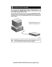
... interface to the RJ-45 ports on your hub by using port 4 on the Model EN104TP hub, port 6 on the Model EN106TP hub, or port 8 on your PC or server and the hub to a PC, use a regular straight-through UTP cable. If you are connecting using twisted pair Ethernet cables. Model EN104TP/EN106TP/EN108TP Ethernet Hub Installation Guide Connect a PC to...
... interface to the RJ-45 ports on your hub by using port 4 on the Model EN104TP hub, port 6 on the Model EN106TP hub, or port 8 on your PC or server and the hub to a PC, use a regular straight-through UTP cable. If you are connecting using twisted pair Ethernet cables. Model EN104TP/EN106TP/EN108TP Ethernet Hub Installation Guide Connect a PC to...
EN104TP Installation Guide
Page 8
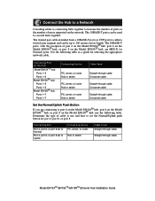
.../Uplink Push Button If you are MDI-X (or Normal) ports. Determine the type of users supported on the Hub Model EN104TP hub: Ports 1-3 Ports 1-3 Model EN106TP hub: Ports 1-5 Ports 1-5 Model EN108TP hub: Ports 1-7 Ports 1-7 Connecting Device PC, server, or router Hub or switch PC, server, or router Hub or switch PC, server, or router Hub or switch Cable Used Straight-through cable Crossover cable Straight...
.../Uplink Push Button If you are MDI-X (or Normal) ports. Determine the type of users supported on the Hub Model EN104TP hub: Ports 1-3 Ports 1-3 Model EN106TP hub: Ports 1-5 Ports 1-5 Model EN108TP hub: Ports 1-7 Ports 1-7 Connecting Device PC, server, or router Hub or switch PC, server, or router Hub or switch PC, server, or router Hub or switch Cable Used Straight-through cable Crossover cable Straight...
EN104TP Installation Guide
Page 9
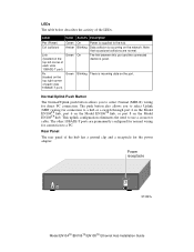
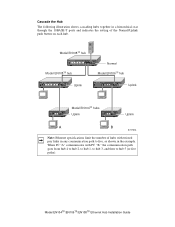
... star through the 10BASE-T ports and indicates the setting of the Normal/Uplink push button on each hub. Model EN108TP hub 10 BASE-T HUB EN108TP Pwr Col 1 2 3 4 5 6 7 8 Normal Model EN108TP hub Model EN106TP hub 10 BASE-T HUB EN108TP Pwr Col 1 2 3 4 5 6 7 8 Uplink 10 BASE-T HUB EN106TP Pwr Col Link/Rx Partition Normal/Uplink 1 2 3 4 5 6 Uplink Model EN104TP hubs Uplink Uplink A B 8727FA Note...
... star through the 10BASE-T ports and indicates the setting of the Normal/Uplink push button on each hub. Model EN108TP hub 10 BASE-T HUB EN108TP Pwr Col 1 2 3 4 5 6 7 8 Normal Model EN108TP hub Model EN106TP hub 10 BASE-T HUB EN108TP Pwr Col 1 2 3 4 5 6 7 8 Uplink 10 BASE-T HUB EN106TP Pwr Col Link/Rx Partition Normal/Uplink 1 2 3 4 5 6 Uplink Model EN104TP hubs Uplink Uplink A B 8727FA Note...
EN104TP Installation Guide
Page 11
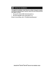
Model EN104TP/EN106TP/EN108TP Ethernet Hub Installation Guide When power has been applied to the hub: • The green Pwr (Power) LED on the front panel is on. • The green Link LED on each connected port is on the wall. If there are any problems, refer to "Troubleshooting Information." Verify the Installation To complete the installation, connect the power cord first to the power receptacle on the hub rear panel and then to the power outlet on .
Model EN104TP/EN106TP/EN108TP Ethernet Hub Installation Guide When power has been applied to the hub: • The green Pwr (Power) LED on the front panel is on. • The green Link LED on each connected port is on the wall. If there are any problems, refer to "Troubleshooting Information." Verify the Installation To complete the installation, connect the power cord first to the power receptacle on the hub rear panel and then to the power outlet on .
EN104TP Installation Guide
Page 12
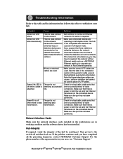
...diagnoses, contact NETGEAR Customer Support. Make sure that home telephone cables can cause a collision condition and cannot be a connected on the defective device on the connected device. Make sure the port has not been partitioned. Model EN104TP/EN106TP/EN108TP Ethernet Hub Installation Guide ...Note that there is power to both the hub and the Ethernet transceiver on the network, network that are not ...
...diagnoses, contact NETGEAR Customer Support. Make sure that home telephone cables can cause a collision condition and cannot be a connected on the defective device on the connected device. Make sure the port has not been partitioned. Model EN104TP/EN106TP/EN108TP Ethernet Hub Installation Guide ...Note that there is power to both the hub and the Ethernet transceiver on the network, network that are not ...
EN104TP Installation Guide
Page 13
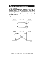
...the receiver of the circuitry in the device. Uplink or MDI port 1 Tx 2 Straight-through and crossover twisted pair cables. Computer and workstation adapter cards are referred to as MDI or Uplink ports. The figures illustrate the use of straight-through twisted pair ...cable Normal or MDI-X port 1 Rx 2 3 Rx 6 3 Tx 6 Normal or MDI-X port 1 Rx 2 Crossover twisted pair cable Normal or MDI-X port 1 Rx 2 3 Tx 6 3 Tx 6 8146EA Model EN104TP/EN106TP/EN108TP Ethernet Hub Installation Guide The crossover function is usually implemented internally as...
...the receiver of the circuitry in the device. Uplink or MDI port 1 Tx 2 Straight-through and crossover twisted pair cables. Computer and workstation adapter cards are referred to as MDI or Uplink ports. The figures illustrate the use of straight-through twisted pair ...cable Normal or MDI-X port 1 Rx 2 3 Rx 6 3 Tx 6 Normal or MDI-X port 1 Rx 2 Crossover twisted pair cable Normal or MDI-X port 1 Rx 2 3 Tx 6 3 Tx 6 8146EA Model EN104TP/EN106TP/EN108TP Ethernet Hub Installation Guide The crossover function is usually implemented internally as...
EN104TP Installation Guide
Page 14
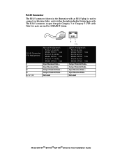
... Connector Pin Assignment Normal Assignment: Ports 1-3 on the Model EN104TP hub Ports 1-5 on the Model EN106TP hub Ports 1-7 on the Model EN108TP hub 1 Input Receive Data + 2 Input Receive Data - 3 Output Transmit Data + 6 Output Transmit Data - 4, 5, 7, 8 Not used 81 711EA Uplink Assignment: Port 4 on the Model EN104TP hub Port 6 on the Model EN106TP hub Port 8 on the Model EN108TP hub Output Transmit Data + Output Transmit...
... Connector Pin Assignment Normal Assignment: Ports 1-3 on the Model EN104TP hub Ports 1-5 on the Model EN106TP hub Ports 1-7 on the Model EN108TP hub 1 Input Receive Data + 2 Input Receive Data - 3 Output Transmit Data + 6 Output Transmit Data - 4, 5, 7, 8 Not used 81 711EA Uplink Assignment: Port 4 on the Model EN104TP hub Port 6 on the Model EN106TP hub Port 8 on the Model EN108TP hub Output Transmit Data + Output Transmit...
EN104TP Installation Guide
Page 15
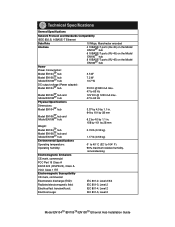
....3i, 10BASE-T Ethernet Data Rate 10 Mbps, Manchester encoded Interface 4 10BASE-T ports (RJ-45) on the Model EN104TP hub 6 10BASE-T ports (RJ-45) on the Model EN106TP hub 8 10BASE-T ports (RJ-45) on the Model EN108TP hub Power Power Consumption: Model EN104TP hub Model EN106TP hub Model EN108TP hub 3.5 W 7.2 W 13.7 W DC output voltage (Power adapter): Model EN104TP hub 5V DC @ 800 mA max.
....3i, 10BASE-T Ethernet Data Rate 10 Mbps, Manchester encoded Interface 4 10BASE-T ports (RJ-45) on the Model EN104TP hub 6 10BASE-T ports (RJ-45) on the Model EN106TP hub 8 10BASE-T ports (RJ-45) on the Model EN108TP hub Power Power Consumption: Model EN104TP hub Model EN106TP hub Model EN108TP hub 3.5 W 7.2 W 13.7 W DC output voltage (Power adapter): Model EN104TP hub 5V DC @ 800 mA max.


