AGM731F Product specification
Page 2
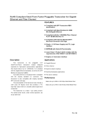
... up to 275m in 62.5/125µm Multi Mode Fiber 2 Rev. 0A It is hot pluggable 3.3V Small-Form-Factor transceiver module designed expressly for IEEE 802.3z/Gigabit Ethernet Compliant with the 1.0625GBd Fiber Channel FC-PI 100-M5-SN-I Rev.13 Compliant...optical power levels, under normal operation, are at eye safe level. RoHS Compliant Small Form Factor Pluggable Transceiver for Gigabit Ethernet and Fiber Channel FEATURES Compliant with SFP Transceiver MSA specification Compliant with Specifications for high-speed communication applications that provides a TTL logic-high output when...
... up to 275m in 62.5/125µm Multi Mode Fiber 2 Rev. 0A It is hot pluggable 3.3V Small-Form-Factor transceiver module designed expressly for IEEE 802.3z/Gigabit Ethernet Compliant with the 1.0625GBd Fiber Channel FC-PI 100-M5-SN-I Rev.13 Compliant...optical power levels, under normal operation, are at eye safe level. RoHS Compliant Small Form Factor Pluggable Transceiver for Gigabit Ethernet and Fiber Channel FEATURES Compliant with SFP Transceiver MSA specification Compliant with Specifications for high-speed communication applications that provides a TTL logic-high output when...
AGM731F Product specification
Page 5
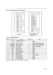
... 3 19 TD- Transmit Data In 3 20 VeeT Transmitter Ground 1 Plug Seq.: Pin engagement sequence during hot plugging. SFP Transceiver Electrical Pad Layout Pin Function Definitions Pin Num. 1 2 Name VeeT TX Fault Function Transmitter Ground Transmitter Fault Indication Plug... Seq. 1 3 3 TX Disable Transmitter Disable 3 4 MOD-DEF2 Module Definition 2 3 5 MOD-DEF1 Module Definition 1 3 6 MOD-DEF0 Module Definition 0 3 7 Rate Select Not Connect 3 8 LOS Loss of Signal 3 9 VeeR Receiver Ground 1 ...
... 3 19 TD- Transmit Data In 3 20 VeeT Transmitter Ground 1 Plug Seq.: Pin engagement sequence during hot plugging. SFP Transceiver Electrical Pad Layout Pin Function Definitions Pin Num. 1 2 Name VeeT TX Fault Function Transmitter Ground Transmitter Fault Indication Plug... Seq. 1 3 3 TX Disable Transmitter Disable 3 4 MOD-DEF2 Module Definition 2 3 5 MOD-DEF1 Module Definition 1 3 6 MOD-DEF0 Module Definition 0 3 7 Rate Select Not Connect 3 8 LOS Loss of Signal 3 9 VeeR Receiver Ground 1 ...
AGM731F Product specification
Page 6
...and VccT are the differential receiver outputs. When the recommended supply-filtering network is used, hot plugging of the SFP transceiver module will be internally connected within the SFP module. 6) RD-/+: These are the receiver and transmitter power supplies. Low indicates normal operation. Pull up voltage between ...7K - 10KΩ resistor on the host board. It is an open collector/drain output, which should be internally connected within the SFP transceiver module. 8) TD-/+: These are : Low (0 - 0.8V): Transmitter on these lines will be pulled to < 0.8V. 5) VeeR ...
...and VccT are the differential receiver outputs. When the recommended supply-filtering network is used, hot plugging of the SFP transceiver module will be internally connected within the SFP module. 6) RD-/+: These are the receiver and transmitter power supplies. Low indicates normal operation. Pull up voltage between ...7K - 10KΩ resistor on the host board. It is an open collector/drain output, which should be internally connected within the SFP transceiver module. 8) TD-/+: These are : Low (0 - 0.8V): Transmitter on these lines will be pulled to < 0.8V. 5) VeeR ...
AGM731F Product specification
Page 8
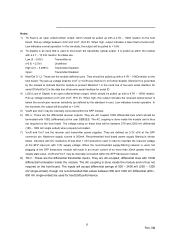
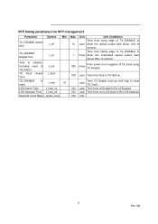
... edge of TX_DISABLE to µsec when the optical output falls below 10% of nominal Time from falling edge of TX_DISABLE to msec when the modulated optical output rises above 90% of nominal From power on or negation of TX_Fault using 300 msec TX Disable. 100 µsec Time from fault...;sec Time from LOS state to Rx LOS assert 100 µsec Time from non-LOS state to Rx LOS deassert 100 kHz 8 Rev. 0A SFP timing parameters for SFP management Parameter TX_DISABLE Assert time Symbol t_off Min.
... edge of TX_DISABLE to µsec when the optical output falls below 10% of nominal Time from falling edge of TX_DISABLE to msec when the modulated optical output rises above 90% of nominal From power on or negation of TX_Fault using 300 msec TX Disable. 100 µsec Time from fault...;sec Time from LOS state to Rx LOS assert 100 µsec Time from non-LOS state to Rx LOS deassert 100 kHz 8 Rev. 0A SFP timing parameters for SFP management Parameter TX_DISABLE Assert time Symbol t_off Min.
AGM731F Product specification
Page 9
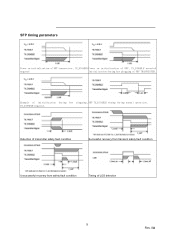
Detection of transmitter safety fault condition Successful recovery from transient safety fault condition Unsuccessful recovery from safety fault condition Timing of LOS detection 9 Rev. 0A Example of initialization during hot plugging, SFP TX_DISABLE timing during hot plugging of SFP TRANSCEIVER. SFP timing parameters Power on initialization of SFP transceiver, TX_DISABLE Power on initialization of SFP, TX_DISABLE asserted negated Initialization during normal operation. TX_DISABLE negated.
Detection of transmitter safety fault condition Successful recovery from transient safety fault condition Unsuccessful recovery from safety fault condition Timing of LOS detection 9 Rev. 0A Example of initialization during hot plugging, SFP TX_DISABLE timing during hot plugging of SFP TRANSCEIVER. SFP timing parameters Power on initialization of SFP transceiver, TX_DISABLE Power on initialization of SFP, TX_DISABLE asserted negated Initialization during normal operation. TX_DISABLE negated.