AGM731F Product specification
Page 2
... Gigabit Ethernet and Fiber Channel FEATURES Compliant with SFP Transceiver MSA specification Compliant with Specifications for high-speed communication applications that provides a TTL logic-high output when an unusable...SFP Multisource Agreement (MSA). The optical power levels, under normal operation, are at eye safe level. The transceiver is compliant with industry standard RFT connector and cage. The post-amplifier of IEC 60825-1 and IEC 60825-2 Duplex LC Connector interface Description Applications This transceiver is hot pluggable 3.3V Small-Form-Factor transceiver module...
... Gigabit Ethernet and Fiber Channel FEATURES Compliant with SFP Transceiver MSA specification Compliant with Specifications for high-speed communication applications that provides a TTL logic-high output when an unusable...SFP Multisource Agreement (MSA). The optical power levels, under normal operation, are at eye safe level. The transceiver is compliant with industry standard RFT connector and cage. The post-amplifier of IEC 60825-1 and IEC 60825-2 Duplex LC Connector interface Description Applications This transceiver is hot pluggable 3.3V Small-Form-Factor transceiver module...

AGM731F Product specification
Page 3
Max. Unit Ts -40 85 ºC VCC 0 5 V Recommended Operating Conditions Parameter Case Operating Temperature Supply Voltage Symbol Min. Unit TC -5 70 ºC VCC 3.135 3.465 V Electrical Characteristics Note Note (VCC=3.135V to 100Ohm differential load. 2. Max. 180 300 2.4 VCC+0.3 0.8 VCC+0.3 0.8 0.7 2 VCC+0.3 0.8 400 220 Unit mA V V V V V V V V psec psec Note 1 2 2 3 2 2 4 Notes: 1. Internally AC coupled and terminated to 3.465V) Parameter Total Supply Current Transmitter Transmitter Differential Input Voltage Transmitter Disable Input-High Transmitter Disable...
Max. Unit Ts -40 85 ºC VCC 0 5 V Recommended Operating Conditions Parameter Case Operating Temperature Supply Voltage Symbol Min. Unit TC -5 70 ºC VCC 3.135 3.465 V Electrical Characteristics Note Note (VCC=3.135V to 100Ohm differential load. 2. Max. 180 300 2.4 VCC+0.3 0.8 VCC+0.3 0.8 0.7 2 VCC+0.3 0.8 400 220 Unit mA V V V V V V V V psec psec Note 1 2 2 3 2 2 4 Notes: 1. Internally AC coupled and terminated to 3.465V) Parameter Total Supply Current Transmitter Transmitter Differential Input Voltage Transmitter Disable Input-High Transmitter Disable...
AGM731F Product specification
Page 4
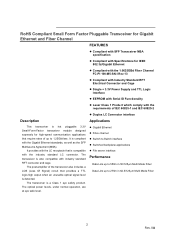
The sensitivity is class 1 laser eye safety Sensitivity (Avg.) Input Optical Wavelength PIN -17 dBm 2 λ 850 nm LOS- Typ. Unit Note Transmitter Output Optical Power (Avg.) PO -9.5 -3 dBm Optical Extinction Ratio Center Wavelength Spectral Width (RMS) ER 9 dB λC 830 850 860 nm σ 0.85 nm Optical Rise/Fall Time Total Jitter (pk-pk) Relative Intensity Noise tr /tf TJTX RIN 260 psec 1 220 psec -117 dB/Hz Output Eye Receiver Complies with the IEEE 802.3z/D2 specification, and is provided at a BER of 1×10⁻¹⁰ or better with an input ...
The sensitivity is class 1 laser eye safety Sensitivity (Avg.) Input Optical Wavelength PIN -17 dBm 2 λ 850 nm LOS- Typ. Unit Note Transmitter Output Optical Power (Avg.) PO -9.5 -3 dBm Optical Extinction Ratio Center Wavelength Spectral Width (RMS) ER 9 dB λC 830 850 860 nm σ 0.85 nm Optical Rise/Fall Time Total Jitter (pk-pk) Relative Intensity Noise tr /tf TJTX RIN 260 psec 1 220 psec -117 dB/Hz Output Eye Receiver Complies with the IEEE 802.3z/D2 specification, and is provided at a BER of 1×10⁻¹⁰ or better with an input ...
AGM731F Product specification
Page 5
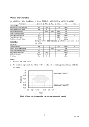
SFP Transceiver Electrical Pad Layout Pin Function Definitions Pin Num. 1 2 Name VeeT TX Fault Function Transmitter Ground Transmitter Fault Indication Plug Seq. 1 3 3 TX Disable Transmitter Disable 3 4 MOD-DEF2 Module Definition 2 3 5 MOD-DEF1 Module Definition 1 3 6 MOD-DEF0 Module Definition 0 3 7 Rate Select Not Connect 3 8 LOS Loss of Signal... VeeT Transmitter Ground 1 Plug Seq.: Pin engagement sequence during hot plugging. Notes Note 1 Note 2 Module disables on high or open Note 3, 2 wire serial ID interface Note 3, 2 wire serial ID interface Note 3, Grounded in...
SFP Transceiver Electrical Pad Layout Pin Function Definitions Pin Num. 1 2 Name VeeT TX Fault Function Transmitter Ground Transmitter Fault Indication Plug Seq. 1 3 3 TX Disable Transmitter Disable 3 4 MOD-DEF2 Module Definition 2 3 5 MOD-DEF1 Module Definition 1 3 6 MOD-DEF0 Module Definition 0 3 7 Rate Select Not Connect 3 8 LOS Loss of Signal... VeeT Transmitter Ground 1 Plug Seq.: Pin engagement sequence during hot plugging. Notes Note 1 Note 2 Module disables on high or open Note 3, 2 wire serial ID interface Note 3, 2 wire serial ID interface Note 3, Grounded in...
AGM731F Product specification
Page 6
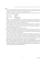
... transmitter inputs. VccR and VccT may be internally connected within the SFP transceiver module. 8) TD-/+: These are defined as defined by the module to < 0.8V. 5) VeeR and VeeT may be internally connected within the SFP module. 6) RD-/+: These are the module definition pins. It is pulled up with a 4.7K - 10K...indicates a laser fault of no more than 30mA greater than 1 ohm should be used , hot plugging of the SFP transceiver module will be pulled to indicate that the module is present Mod-Def 1 is the clock line of two wire serial interface for serial ID Mod-Def 2 ...
... transmitter inputs. VccR and VccT may be internally connected within the SFP transceiver module. 8) TD-/+: These are defined as defined by the module to < 0.8V. 5) VeeR and VeeT may be internally connected within the SFP module. 6) RD-/+: These are the module definition pins. It is pulled up with a 4.7K - 10K...indicates a laser fault of no more than 30mA greater than 1 ohm should be used , hot plugging of the SFP transceiver module will be pulled to indicate that the module is present Mod-Def 1 is the clock line of two wire serial interface for serial ID Mod-Def 2 ...
AGM731F Product specification
Page 7
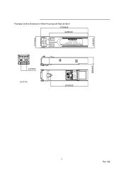
Package Outline Drawing for Metal Housing with Bail de-latch AGM731F 850nm 1.25GBd 1000Base-SX / LC Connector Class 1 Laser Proudct R 272-10254-02 Complies with 21 CFR 1040.10 and 1040.11 Made in China 7 Rev. 0A
Package Outline Drawing for Metal Housing with Bail de-latch AGM731F 850nm 1.25GBd 1000Base-SX / LC Connector Class 1 Laser Proudct R 272-10254-02 Complies with 21 CFR 1040.10 and 1040.11 Made in China 7 Rev. 0A
AGM731F Product specification
Page 8
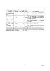
SFP timing parameters for SFP management Parameter TX_DISABLE Assert time Symbol t_off Min. TX_DISABLE Negate time t_on Time to initialize, including reset of t_init TX_FAULT TX Fault Assert t_fault Time ... edge of TX_DISABLE to µsec when the optical output falls below 10% of nominal Time from falling edge of TX_DISABLE to msec when the modulated optical output rises above 90% of nominal From power on or negation of TX_Fault using 300 msec TX Disable. 100 µsec Time from fault...
SFP timing parameters for SFP management Parameter TX_DISABLE Assert time Symbol t_off Min. TX_DISABLE Negate time t_on Time to initialize, including reset of t_init TX_FAULT TX Fault Assert t_fault Time ... edge of TX_DISABLE to µsec when the optical output falls below 10% of nominal Time from falling edge of TX_DISABLE to msec when the modulated optical output rises above 90% of nominal From power on or negation of TX_Fault using 300 msec TX Disable. 100 µsec Time from fault...
AGM731F Product specification
Page 9
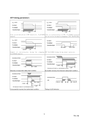
Example of LOS detection 9 Rev. 0A TX_DISABLE negated. Detection of transmitter safety fault condition Successful recovery from transient safety fault condition Unsuccessful recovery from safety fault condition Timing of initialization during hot plugging, SFP TX_DISABLE timing during hot plugging of SFP TRANSCEIVER. SFP timing parameters Power on initialization of SFP transceiver, TX_DISABLE Power on initialization of SFP, TX_DISABLE asserted negated Initialization during normal operation.
Example of LOS detection 9 Rev. 0A TX_DISABLE negated. Detection of transmitter safety fault condition Successful recovery from transient safety fault condition Unsuccessful recovery from safety fault condition Timing of initialization during hot plugging, SFP TX_DISABLE timing during hot plugging of SFP TRANSCEIVER. SFP timing parameters Power on initialization of SFP transceiver, TX_DISABLE Power on initialization of SFP, TX_DISABLE asserted negated Initialization during normal operation.
AGM731F Product specification
Page 10
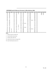
EEPROM Serial ID Memory Contents (2-Wire Address A0h) Address Hex ASCII Address Hex ASCII Address Hex ASCII Address Hex ASCII Address Hex ASCII Address Hex ASCII 00 03 25 41 A 50 20 75 SN 100 00 125 00 01 04 26 52 R 51 20 76 SN 101 00 126 00 02 07 27 20 52 20 77 SN 102 00 127 00 03 00 28 20 53 20 78 SN 103 00 04 00 29 20 54 20 79 SN 104 00 05 00 30 20 55 20 80 SN 105 00 06 01 31 20 56 41 81 SN 106 00 07 40 32 20 57 20 82 SN 107 00 08 40 33 20 58 20 83 SN 108 00 09 00 34 20 59 20 84 DC Note 3 109 00 10 00 35 20 60 03 85 DC 110 00 11 03...
EEPROM Serial ID Memory Contents (2-Wire Address A0h) Address Hex ASCII Address Hex ASCII Address Hex ASCII Address Hex ASCII Address Hex ASCII Address Hex ASCII 00 03 25 41 A 50 20 75 SN 100 00 125 00 01 04 26 52 R 51 20 76 SN 101 00 126 00 02 07 27 20 52 20 77 SN 102 00 127 00 03 00 28 20 53 20 78 SN 103 00 04 00 29 20 54 20 79 SN 104 00 05 00 30 20 55 20 80 SN 105 00 06 01 31 20 56 41 81 SN 106 00 07 40 32 20 57 20 82 SN 107 00 08 40 33 20 58 20 83 SN 108 00 09 00 34 20 59 20 84 DC Note 3 109 00 10 00 35 20 60 03 85 DC 110 00 11 03...
AGM731F Product specification
Page 11
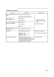
R50032471 Component Recognition Underwriters Laboratories and UL File # E239394 Canadian Standards Association Joint Component Recognition for Information Technology Equipment Including Electrical Business Equipment 11 Rev. 0A Regulatory Compliance Feature Reference Electromagnetic Interference FCC CRF 47, Part15 Class B (EMI) EN 55022 Class B (CISPR 22A) Performance Radio Frequency Electromagnetic Field EN 61000-4-3 IEC 61000-4-3 Electrostatic Discharge to the EN 61000-4-2 Duplex LC Receptacle IEC 61000-4-2 IEC 801.2 (1) Satisfied with electrical characteristics of product ...
R50032471 Component Recognition Underwriters Laboratories and UL File # E239394 Canadian Standards Association Joint Component Recognition for Information Technology Equipment Including Electrical Business Equipment 11 Rev. 0A Regulatory Compliance Feature Reference Electromagnetic Interference FCC CRF 47, Part15 Class B (EMI) EN 55022 Class B (CISPR 22A) Performance Radio Frequency Electromagnetic Field EN 61000-4-3 IEC 61000-4-3 Electrostatic Discharge to the EN 61000-4-2 Duplex LC Receptacle IEC 61000-4-2 IEC 801.2 (1) Satisfied with electrical characteristics of product ...

AGM731F Product specification
Page 12
All rights reserved. in the United States and/or other countries. Information is subject to change without notice. D-AGM731F-0 NETGEAR, the NETGEAR Logo, NETGEAR Digital Entertainer Logo, Connect with Innovation, FrontView, IntelliFi, PowerShift, ProSafe, RAIDar, RAIDiator, X-RAID, RangeMax, ReadyNAS and Smart Wizard are for identification purposes only and may be trademarks of NETGEAR, Inc. Other brand names mentioned herein are trademarks of their respective holder(s). © 2008 NETGEAR, Inc.
All rights reserved. in the United States and/or other countries. Information is subject to change without notice. D-AGM731F-0 NETGEAR, the NETGEAR Logo, NETGEAR Digital Entertainer Logo, Connect with Innovation, FrontView, IntelliFi, PowerShift, ProSafe, RAIDar, RAIDiator, X-RAID, RangeMax, ReadyNAS and Smart Wizard are for identification purposes only and may be trademarks of NETGEAR, Inc. Other brand names mentioned herein are trademarks of their respective holder(s). © 2008 NETGEAR, Inc.