User Manual
Page 8
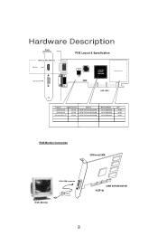
Hardware Description Plate PCB Layout & Specification 3DForce2 MX-LCD ONLY DVI Out nVIDIA GeForce2 MX400 Display Memory Y1 DB 15 VGA AGP BUS Product / PCB Reversion 3DForce2 MX 82118A 3DForce2 MX 82118D 3DForce2 MX-LCD 82118A Chipset nVIDIA GeForce2 MX/MX400 nVIDIA GeForce2 MX/MX400 nVIDIA GeForce2 MX/MX400 Memory Model / 2M*32 SDRAMx4 2M*32 SDRAMx4 2M*32 SDRAMx4 Size 32 MB 32 MB 32 MB RGB Monitor Connection 3DForce2 MX 15Pin RGB connector RGB Monitor RGB Out 32MB SDRAM/SGRAM AGP 4x 8
Hardware Description Plate PCB Layout & Specification 3DForce2 MX-LCD ONLY DVI Out nVIDIA GeForce2 MX400 Display Memory Y1 DB 15 VGA AGP BUS Product / PCB Reversion 3DForce2 MX 82118A 3DForce2 MX 82118D 3DForce2 MX-LCD 82118A Chipset nVIDIA GeForce2 MX/MX400 nVIDIA GeForce2 MX/MX400 nVIDIA GeForce2 MX/MX400 Memory Model / 2M*32 SDRAMx4 2M*32 SDRAMx4 2M*32 SDRAMx4 Size 32 MB 32 MB 32 MB RGB Monitor Connection 3DForce2 MX 15Pin RGB connector RGB Monitor RGB Out 32MB SDRAM/SGRAM AGP 4x 8
User Manual
Page 9
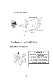
LCD Display Panel Connection 3DForce2 MX-LCD DVI Out Digital Video Interface AGP 4x 32MB Frame Buffer Hardware Installation Installation Procedures !! WARNING !! Discharge static electricity by touching the GROUND such as metal part of your case connected with good power ground before you handle the electronic circuit boards. 9
LCD Display Panel Connection 3DForce2 MX-LCD DVI Out Digital Video Interface AGP 4x 32MB Frame Buffer Hardware Installation Installation Procedures !! WARNING !! Discharge static electricity by touching the GROUND such as metal part of your case connected with good power ground before you handle the electronic circuit boards. 9