
42PD2/50PD1
Page 2
... inserted. 3. Use a soft dry cloth to authorized NEC Service Centers. 8. The plasma display panel consists of the Canadian Interference-Causing Equipment Regulations. Although NEC produces the plasma display panels with the instruction manual, may have sufficient magnitude to rise and escape. Do not cover rear vents or install in an enclosure, be void. If you install the unit in a closed cabinet or shelves. If the monitor becomes...
... inserted. 3. Use a soft dry cloth to authorized NEC Service Centers. 8. The plasma display panel consists of the Canadian Interference-Causing Equipment Regulations. Although NEC produces the plasma display panels with the instruction manual, may have sufficient magnitude to rise and escape. Do not cover rear vents or install in an enclosure, be void. If you install the unit in a closed cabinet or shelves. If the monitor becomes...
42PD2/50PD1
Page 3
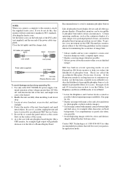
... modes of the screen. 6. Use complementary or pastel color whenever possible. * Avoid displaying images with 120V 50/60Hz AC power supply. Close the lid tightly until the clamps click. In case of time, can be susceptible to the following guidelines and recommendations for instructions on black backgrounds. To protect your PlasmaSync PD Series monitor to diminish its perceptible effects if it serviced by an authorized NEC Service...
... modes of the screen. 6. Use complementary or pastel color whenever possible. * Avoid displaying images with 120V 50/60Hz AC power supply. Close the lid tightly until the clamps click. In case of time, can be susceptible to the following guidelines and recommendations for instructions on black backgrounds. To protect your PlasmaSync PD Series monitor to diminish its perceptible effects if it serviced by an authorized NEC Service...
42PD2/50PD1
Page 6
... warranty: 1. d. Burns or residual images upon inconvenience, loss of use of the product, loss of initial technical adjustments (set forth in this warranty statement, we have prior approval. e. HOW YOU CAN GET WARRANTY SERVICE 1. Accident, misuse, abuse, neglect, fire, water, light- Costs of time, commercial loss; HOW STATE LAW RELATES TO THE WARRANTY This warranty gives you specific legal rights...
... warranty: 1. d. Burns or residual images upon inconvenience, loss of use of the product, loss of initial technical adjustments (set forth in this warranty statement, we have prior approval. e. HOW YOU CAN GET WARRANTY SERVICE 1. Accident, misuse, abuse, neglect, fire, water, light- Costs of time, commercial loss; HOW STATE LAW RELATES TO THE WARRANTY This warranty gives you specific legal rights...
42PD2/50PD1
Page 7
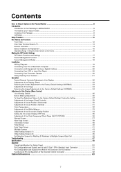
... Screen Position (Vertical 31 Color Temperature ...32 Adjustment of the White Balance 33 Adjustment of the On-screen Display Position 34 Setting the On-screen Display OFF Time 35 Adjustment of the Clock Frequency/Clock Phase (AUTO PICTURE 36 Normal Screen ...37 Next Page Screen ...38 Information Screen ...39 Timer Screen ...40 Auto Timer Screen ...41 Multiple Screens ...43 Other Setting Screens (1) ...44 Other Setting Screens (2) ...45 Set Selection Screen for Allotting ID Numbers to Multiple Screens/Each Set 46 Troubleshooting ...47 Specifications ...48 Appendix Signal...
... Screen Position (Vertical 31 Color Temperature ...32 Adjustment of the White Balance 33 Adjustment of the On-screen Display Position 34 Setting the On-screen Display OFF Time 35 Adjustment of the Clock Frequency/Clock Phase (AUTO PICTURE 36 Normal Screen ...37 Next Page Screen ...38 Information Screen ...39 Timer Screen ...40 Auto Timer Screen ...41 Multiple Screens ...43 Other Setting Screens (1) ...44 Other Setting Screens (2) ...45 Set Selection Screen for Allotting ID Numbers to Multiple Screens/Each Set 46 Troubleshooting ...47 Specifications ...48 Appendix Signal...
42PD2/50PD1
Page 9
... which are supported by cable connection) and the remote THROUGH OUT connector permits simultaneous operation of multiple monitors. (A maximum of 3 units can be selected on the screen to allow fine settings to be made. * Plug and Play compatible The RGB3 input is equipped with its own THROUGH OUT connector, single system. * Can be used with Digital RGB input (DVI standard compliant) * Can be used as a wireless or...
... which are supported by cable connection) and the remote THROUGH OUT connector permits simultaneous operation of multiple monitors. (A maximum of 3 units can be selected on the screen to allow fine settings to be made. * Plug and Play compatible The RGB3 input is equipped with its own THROUGH OUT connector, single system. * Can be used with Digital RGB input (DVI standard compliant) * Can be used as a wireless or...
42PD2/50PD1
Page 10
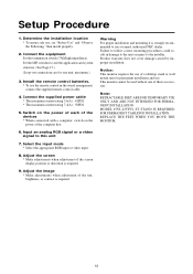
Setup Procedure 1. Connect the equipment Set the termination switch (75Ω/high impedance). Select the input mode * Select the appropriate RGB input or video input. 8. Failure to follow correct mounting procedures could result in the wired arrangement, connect the supplied remote control cable. 4. Notice: This monitor requires the use of these accessories. Note: RETRACTABLE FEET ARE FOR TEMPORARY USE ONLY AND ARE NOT INTENDED FOR PERMANENT INSTALLATION. Connect the supplied power cable * The maximum...
Setup Procedure 1. Connect the equipment Set the termination switch (75Ω/high impedance). Select the input mode * Select the appropriate RGB input or video input. 8. Failure to follow correct mounting procedures could result in the wired arrangement, connect the supplied remote control cable. 4. Notice: This monitor requires the use of these accessories. Note: RETRACTABLE FEET ARE FOR TEMPORARY USE ONLY AND ARE NOT INTENDED FOR PERMANENT INSTALLATION. Connect the supplied power cable * The maximum...

42PD2/50PD1
Page 12
... "CONTROL LOCK" toggle switch on the monitor's input panel is set to the signal connected with the RGB input connector. (Toggle switches between RGB1/RGB2/ RGB3.) Functions as the (+) button in the on-screen display (OSM) mode. 3 VIDEO button Switches to "ON", the buttons on the set's front bezel control panel do not function. 12 Part Names and Functions Front View 12 3 4 5 6 7 8 9 1 POWER/STANDBY The lamp color indicates the mode of power on/standby or power management. 5 UP button Functions as the (v) button...
... "CONTROL LOCK" toggle switch on the monitor's input panel is set to the signal connected with the RGB input connector. (Toggle switches between RGB1/RGB2/ RGB3.) Functions as the (+) button in the on-screen display (OSM) mode. 3 VIDEO button Switches to "ON", the buttons on the set's front bezel control panel do not function. 12 Part Names and Functions Front View 12 3 4 5 6 7 8 9 1 POWER/STANDBY The lamp color indicates the mode of power on/standby or power management. 5 UP button Functions as the (v) button...
42PD2/50PD1
Page 13
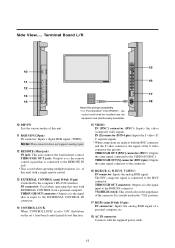
...;/HIGH switch: This switch selects the impedance of a personal computer, etc. 18 AC IN connector Connects with the supplied power cable. 13 THROUGH OUT connector: Outputs as is the remote control signal that is input to the EXTERNAL CONTROL IN connector. 14 CONTROL LOCK When "CONTROL LOCK" is connected to the H/CS connector. IN [S] connector (DIN 4 pin): Inputs the S video (Y/ C separate signal). * When connections are made to "ON", the buttons on the set to...
...;/HIGH switch: This switch selects the impedance of a personal computer, etc. 18 AC IN connector Connects with the supplied power cable. 13 THROUGH OUT connector: Outputs as is the remote control signal that is input to the EXTERNAL CONTROL IN connector. 14 CONTROL LOCK When "CONTROL LOCK" is connected to the H/CS connector. IN [S] connector (DIN 4 pin): Inputs the S video (Y/ C separate signal). * When connections are made to "ON", the buttons on the set to...
42PD2/50PD1
Page 16
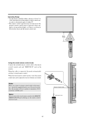
.... When the wired remote control mode is connected, the mode automatically switches to the REMOTE THROUGH OUT jack. Approx. 7m/23ft 30˚ 30˚ POWER OFF POWER ON RGB 2 RGB 1 RGB 3 VIDEO POSITION / CONTR OL EXIT PROCEED RGB/VIDEO CONTRAST BRIGHT VIDEO COLOR TINT SHARPNESS VISUAL NORMAL RASTER NORMAL ID SELECT CLEAR Using the wired remote control mode Connect the included remote control cable to this monitor will not conform to...
.... When the wired remote control mode is connected, the mode automatically switches to the REMOTE THROUGH OUT jack. Approx. 7m/23ft 30˚ 30˚ POWER OFF POWER ON RGB 2 RGB 1 RGB 3 VIDEO POSITION / CONTR OL EXIT PROCEED RGB/VIDEO CONTRAST BRIGHT VIDEO COLOR TINT SHARPNESS VISUAL NORMAL RASTER NORMAL ID SELECT CLEAR Using the wired remote control mode Connect the included remote control cable to this monitor will not conform to...

42PD2/50PD1
Page 17
... time. Sync control setting Automatic Manual 1 (Composite) Manual 2 (Sync-on -screen display (OSM) * Set to "OFF" when displays are not desired. Note: that use of wireless remote control * When using multiple units under wireless remote control operation, the remote control signal also enters other monitors and may be disturbed. Setting details 1 On-off switching of on -screen display. Set to "ON" when performing adjustments and viewing displays with something fine and pointed such as a miniature screwdriver or the tip of wireless remote control 3 Sync control mode 4 Setting...
... time. Sync control setting Automatic Manual 1 (Composite) Manual 2 (Sync-on -screen display (OSM) * Set to "OFF" when displays are not desired. Note: that use of wireless remote control * When using multiple units under wireless remote control operation, the remote control signal also enters other monitors and may be disturbed. Setting details 1 On-off switching of on -screen display. Set to "ON" when performing adjustments and viewing displays with something fine and pointed such as a miniature screwdriver or the tip of wireless remote control 3 Sync control mode 4 Setting...

42PD2/50PD1
Page 18
... DPMS "off in which the unit is set . (This power state is equivalent to video will be displayed about 4 seconds after the input of the horizontal/vertical sync signal. The image will be displayed about 4 seconds Remote control in standby mode Power cord not connected * Standby suspend, off " state.) Displayed approximately 4 seconds after the input of the display becomes operational when the monitor is used for a fixed period. To see the operating system (OS...
... DPMS "off in which the unit is set . (This power state is equivalent to video will be displayed about 4 seconds after the input of the horizontal/vertical sync signal. The image will be displayed about 4 seconds Remote control in standby mode Power cord not connected * Standby suspend, off " state.) Displayed approximately 4 seconds after the input of the display becomes operational when the monitor is used for a fixed period. To see the operating system (OS...
42PD2/50PD1
Page 20
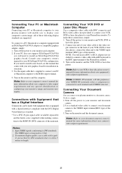
... laser disc player owner's manual for installation instructions. 3. If you need to install an XGA/SuperVGA/VGA graphics board. Turn on the monitor and the VCR, DVD or laser disc player. Connect one end of the monitor. Connecting Your Document Camera You can be made with the DVI (Digital Visual Interface) standard. * Use a DVI 29-pin signal cable (available separately) and the ferrite cores (supplied) when making connections to the RGB3 IN (DVI) connector...
... laser disc player owner's manual for installation instructions. 3. If you need to install an XGA/SuperVGA/VGA graphics board. Turn on the monitor and the VCR, DVD or laser disc player. Connect one end of the monitor. Connecting Your Document Camera You can be made with the DVI (Digital Visual Interface) standard. * Use a DVI 29-pin signal cable (available separately) and the ferrite cores (supplied) when making connections to the RGB3 IN (DVI) connector...
42PD2/50PD1
Page 22
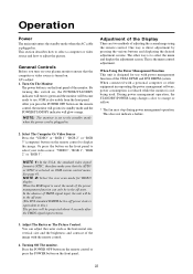
... green and the monitor will become ready to the standby mode when the power cord is on the front panel of TMDS signal input, the unit will turn on your video source: "VIDEO", "RGB 1", "RGB 2" or "RGB 3". During power management operation, the STANDBY/POWER lamp changes color to adjust the picture. NOTE 1: In the U.S.A. You can only be in . Turn On The Monitor The power button is plugged in the off power state is designed for VIDEO display...
... green and the monitor will become ready to the standby mode when the power cord is on the front panel of TMDS signal input, the unit will turn on your video source: "VIDEO", "RGB 1", "RGB 2" or "RGB 3". During power management operation, the STANDBY/POWER lamp changes color to adjust the picture. NOTE 1: In the U.S.A. You can only be in . Turn On The Monitor The power button is plugged in the off power state is designed for VIDEO display...

42PD2/50PD1
Page 23
... button during the on . At this time the following settings of the menu control will also simultaneously return to the factory default setting. * H-POSITION 1,2 and V-POSITION 1,2 are not available at the time of the PROCEED button will return only the display item to the factory default settings: AUTO PICTURE, PICTURE ADJUST, FINE PICTURE, H/V-POSITION 1, H/V-POSITION 2, HWIDTH (Multiple Screens only), V-HEIGHT (Multiple Screens only) and OSM location. 1. Adjustment of the Display (Direct) Press the buttons of screen size...
... button during the on . At this time the following settings of the menu control will also simultaneously return to the factory default setting. * H-POSITION 1,2 and V-POSITION 1,2 are not available at the time of the PROCEED button will return only the display item to the factory default settings: AUTO PICTURE, PICTURE ADJUST, FINE PICTURE, H/V-POSITION 1, H/V-POSITION 2, HWIDTH (Multiple Screens only), V-HEIGHT (Multiple Screens only) and OSM location. 1. Adjustment of the Display (Direct) Press the buttons of screen size...

42PD2/50PD1
Page 25
Adjustment of the Display (Menu Control) Use of the on-screen display (OSM) function allows the setting of dark images (dark colors) OSM Location OSM H-Position OSM V-Position OSM Angle OSM Display Time On-screen adjustment On-screen horizontal position adjustment On-screen vertical position adjustment On-screen angle setting (Horizontal and vertical display) On-screen display OFF time setting Auto Picture Normal Auto Picture INPUT MODE RGB MODE Picture ADJ Fine Picture WIDE MODE All Visual Normal All Raster Normal All Normal Used to be made while viewing this display. The...
Adjustment of the Display (Menu Control) Use of the on-screen display (OSM) function allows the setting of dark images (dark colors) OSM Location OSM H-Position OSM V-Position OSM Angle OSM Display Time On-screen adjustment On-screen horizontal position adjustment On-screen vertical position adjustment On-screen angle setting (Horizontal and vertical display) On-screen display OFF time setting Auto Picture Normal Auto Picture INPUT MODE RGB MODE Picture ADJ Fine Picture WIDE MODE All Visual Normal All Raster Normal All Normal Used to be made while viewing this display. The...

42PD2/50PD1
Page 26
...Display mode display Display source (VIDEO/RGB1,2,3) Horizontal frequency (kHz) Vertical frequency (Hz) Polarity of horizontal sync Neg./Pos. (Negative polarity/Positive polarity) Polarity of vertical sync Neg./Pos. (Negative polarity/Positive polarity) Present Time Timer ON/OFF time and mode setting Multiple screens settings Screen division setting Screen division position setting Color system setting Power ON mode setting Power management setting External control setting Settings reset Long life mode 1 setting Long life mode 2 setting Long life mode 3 setting Gray level setting Set ID number...
...Display mode display Display source (VIDEO/RGB1,2,3) Horizontal frequency (kHz) Vertical frequency (Hz) Polarity of horizontal sync Neg./Pos. (Negative polarity/Positive polarity) Polarity of vertical sync Neg./Pos. (Negative polarity/Positive polarity) Present Time Timer ON/OFF time and mode setting Multiple screens settings Screen division setting Screen division position setting Color system setting Power ON mode setting Power management setting External control setting Settings reset Long life mode 1 setting Long life mode 2 setting Long life mode 3 setting Gray level setting Set ID number...
42PD2/50PD1
Page 36
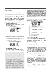
... image to be Clock phase adjustment Clock frequency adjustment INPUT MODE: 4 X 3 / 16 X 9 Select with the POSITION CONTROL ᮤ / ᮣ buttons. After selecting the desired setting, go to the Auto menu, set to OFF. Align the cursor withAUTO PICTURE and set auto picture to OFF and use the POSITION LEFT/RIGHT control to select 4 x 3. Selecting Native Resolutions for the first time and you to fine tune the computer image or to remove vertical...
... image to be Clock phase adjustment Clock frequency adjustment INPUT MODE: 4 X 3 / 16 X 9 Select with the POSITION CONTROL ᮤ / ᮣ buttons. After selecting the desired setting, go to the Auto menu, set to OFF. Align the cursor withAUTO PICTURE and set auto picture to OFF and use the POSITION LEFT/RIGHT control to select 4 x 3. Selecting Native Resolutions for the first time and you to fine tune the computer image or to remove vertical...
42PD2/50PD1
Page 37
... adjustment * Clock phase adjustment (Fine Picture) Adjust the phase of the clock and adjust the (+) and (-) buttons so that screen noise, flicker, and color infidelity are two controls in the Plasma monitor OSM menus that only NORMAL/FULL area available in still picture mode, the screen will display the signal at 848 x 480. When inputting an 848 x 480 signal, align the cursor at the time of VIDEO and S-VIDEO input. * To reset the adjustment...
... adjustment * Clock phase adjustment (Fine Picture) Adjust the phase of the clock and adjust the (+) and (-) buttons so that screen noise, flicker, and color infidelity are two controls in the Plasma monitor OSM menus that only NORMAL/FULL area available in still picture mode, the screen will display the signal at 848 x 480. When inputting an 848 x 480 signal, align the cursor at the time of VIDEO and S-VIDEO input. * To reset the adjustment...
42PD2/50PD1
Page 47
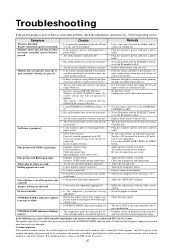
... turn off ? • Has an ID number been set the ID number to ALL. • Replace both batteries with new ones. • The front panel buttons do not function • Is the monitor's power cord plugged into a power outlet? • Are all connections. Part of DIP SW (Wireless) When in orange or yellow. The remote cable is piugged into a power outlet. • Be sure wall switch is on . • POWER/STANDBY indicatoris flashing red...
... turn off ? • Has an ID number been set the ID number to ALL. • Replace both batteries with new ones. • The front panel buttons do not function • Is the monitor's power cord plugged into a power outlet? • Are all connections. Part of DIP SW (Wireless) When in orange or yellow. The remote cable is piugged into a power outlet. • Be sure wall switch is on . • POWER/STANDBY indicatoris flashing red...
42PD2/50PD1
Page 50
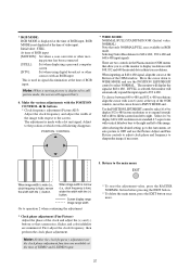
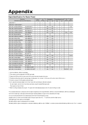
... images of video games, etc., are input. (In this resolution. *848 dot by 480 line signals are displayed at the center. *4 The picture will not be displayed properly unless the correct settings are Sync On Green. *7 Make the settings to display these signals. Y Y - 4 X 3 Y Y - - Y Y - - Y Y - - Y Y - - Y Y - - For some signals are input. *Multiple screens (2 screens) can only display signals having an aspect ratio of 4:3. *3 Cannot be used with multiple screens. *With digital inputs some models, make the mini D-Sub 15-pin connection using...
... images of video games, etc., are input. (In this resolution. *848 dot by 480 line signals are displayed at the center. *4 The picture will not be displayed properly unless the correct settings are Sync On Green. *7 Make the settings to display these signals. Y Y - 4 X 3 Y Y - - Y Y - - Y Y - - Y Y - - Y Y - - For some signals are input. *Multiple screens (2 screens) can only display signals having an aspect ratio of 4:3. *3 Cannot be used with multiple screens. *With digital inputs some models, make the mini D-Sub 15-pin connection using...


