NP115 : ceiling plate instruction
Page 1
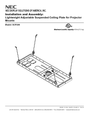
Installation and Assembly: Lightweight Adjustable Suspended Ceiling Plate for Projector Mounts Model: SCP200 C U© L US Maximum Load UL Capacity: 60 lb (27.2 kg) ISSUED: 12-16-04 SHEET #: 120-9015-3 11-05-10 3215 W. North Ave. • Melrose Park, IL 60160 • (800) 865-2112 or (708) 865-8870 • Fax: (708) 865-2941 • www.peerlessmounts.com NEC DISPLAY SOLUTIONS OF AMERICA, INC.
Installation and Assembly: Lightweight Adjustable Suspended Ceiling Plate for Projector Mounts Model: SCP200 C U© L US Maximum Load UL Capacity: 60 lb (27.2 kg) ISSUED: 12-16-04 SHEET #: 120-9015-3 11-05-10 3215 W. North Ave. • Melrose Park, IL 60160 • (800) 865-2112 or (708) 865-8870 • Fax: (708) 865-2941 • www.peerlessmounts.com NEC DISPLAY SOLUTIONS OF AMERICA, INC.
NP115 : ceiling plate instruction
Page 2
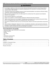
... Ceiling Plate ...5 Warranty Information ...6 Visit the Peerless Web Site at www.peerlessmounts.com 2 of 6 ISSUED: 12-16-04 SHEET #: 120-9015-3 11-05-10 For Technical Support Contact Peerless Mounts at 1-800-729-0307. • This product should only be installed by someone of ...the instructions and warnings contained in this product outdoors could lead to product failure and personal injury. • When installing or adjusting the ceiling mount, do not overtighten. Overtightening can damage the items, greatly reducing their holding power. Tools Needed for Assembly • stud fi...
... Ceiling Plate ...5 Warranty Information ...6 Visit the Peerless Web Site at www.peerlessmounts.com 2 of 6 ISSUED: 12-16-04 SHEET #: 120-9015-3 11-05-10 For Technical Support Contact Peerless Mounts at 1-800-729-0307. • This product should only be installed by someone of ...the instructions and warnings contained in this product outdoors could lead to product failure and personal injury. • When installing or adjusting the ceiling mount, do not overtighten. Overtightening can damage the items, greatly reducing their holding power. Tools Needed for Assembly • stud fi...
NP115 : ceiling plate instruction
Page 3
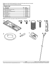
A B D F G H J C I cable lock J escutcheon plate Qty. Parts List Description A ceiling plate B M5 x 10 mm penta pin screw C M5 penta pin driver D M5 x 10 mm self tapping screw E steel cable F flush mount tube G wood screw H concrete anchor I E Visit the Peerless Web Site at www.peerlessmounts.com 3 of the parts shown are included. Before you start... 1 1418-001A NOTE: Some parts may not need all of 6 ISSUED: 12-16-04 SHEET #: 120-9015-3 11-05-10 For Technical Support Contact Peerless Mounts at 1-800-729-0307 or 708-865-8870.
A B D F G H J C I cable lock J escutcheon plate Qty. Parts List Description A ceiling plate B M5 x 10 mm penta pin screw C M5 penta pin driver D M5 x 10 mm self tapping screw E steel cable F flush mount tube G wood screw H concrete anchor I E Visit the Peerless Web Site at www.peerlessmounts.com 3 of the parts shown are included. Before you start... 1 1418-001A NOTE: Some parts may not need all of 6 ISSUED: 12-16-04 SHEET #: 120-9015-3 11-05-10 For Technical Support Contact Peerless Mounts at 1-800-729-0307 or 708-865-8870.
NP115 : ceiling plate instruction
Page 4
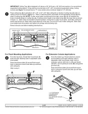
... BOLT OUTSIDE FLANGE D WING NUTS CEILING RUNNER FIGURE 1.1 D FIGURE 1.2 For Flush Mounting Applications 2 From the top down, thread flush mount tube (F) down through retaining collar in collar mount plate, mark false ceiling tile where hole will be mounted above a 24" (610 mm) x 24" (610 mm) section of ceiling tray (A) rests on ceiling tray (A). Align notch in extension...
... BOLT OUTSIDE FLANGE D WING NUTS CEILING RUNNER FIGURE 1.1 D FIGURE 1.2 For Flush Mounting Applications 2 From the top down, thread flush mount tube (F) down through retaining collar in collar mount plate, mark false ceiling tile where hole will be mounted above a 24" (610 mm) x 24" (610 mm) section of ceiling tray (A) rests on ceiling tray (A). Align notch in extension...

NP115 : ceiling plate instruction
Page 5
... this step is a registered trademark of Peerless Industries, Inc. Hammer in figure 5.1. E FIGURE 5.1 DETAIL 3 - All other end of the ceiling tray should be supported by the steel cables. TOP VIEW BLACK RECTANGLES REPRESENT CORRECT POSITIONS FOR STEEL WIRE I ) as shown below. Peerless is complete, ...-3 11-05-10 Visit the Peerless Web Site at www.peerlessmounts.com For Technical Support Contact Peerless Mounts at 15°. Loop E upper end of steel cable (E) G around ceiling truss and down into hole of 1.5" (38 mm). Route steel wires through hole of steel cable...
... this step is a registered trademark of Peerless Industries, Inc. Hammer in figure 5.1. E FIGURE 5.1 DETAIL 3 - All other end of the ceiling tray should be supported by the steel cables. TOP VIEW BLACK RECTANGLES REPRESENT CORRECT POSITIONS FOR STEEL WIRE I ) as shown below. Peerless is complete, ...-3 11-05-10 Visit the Peerless Web Site at www.peerlessmounts.com For Technical Support Contact Peerless Mounts at 15°. Loop E upper end of steel cable (E) G around ceiling truss and down into hole of 1.5" (38 mm). Route steel wires through hole of steel cable...
NP216 : NP01UCM (ceiling mount) instructions
Page 1
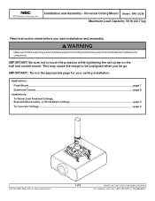
... may cause the image to be unaligned when you start installation and assembly. Applications: Flush Mount ...page 7 Extension Column ...page 8 Installations: To Wood Joist Finished Ceilings, Exposed Wood Joists, or Wood Beam Ceilings page 5 To Concrete Ceilings ...page 6 Visit the NEC Web Site at www.necsam.com 1 of the equipment and all attached hardware and...
... may cause the image to be unaligned when you start installation and assembly. Applications: Flush Mount ...page 7 Extension Column ...page 8 Installations: To Wood Joist Finished Ceilings, Exposed Wood Joists, or Wood Beam Ceilings page 5 To Concrete Ceilings ...page 6 Visit the NEC Web Site at www.necsam.com 1 of the equipment and all attached hardware and...
NP216 : NP01UCM (ceiling mount) instructions
Page 3
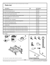
A ball and socket mount 1 B 4 mm security allen wrench 1 C M5 x .8 x 10 mm socket pin type F screw 1 D #10-32 x 3/8" spade thumb screw 1 E #10-32 x 3/8" serrated washer head socket pin screw 1 F #14 x 2.5 phillips hex head wood screw 2 G ceiling plate 1 H .25" ID x .56" OD x .26 spacer 2 I extension column connector with cord ...510-2066 560-1097 540-2025 JE L D H RK F Note: Actual parts may appear slightly different than illustrated. Visit the NEC Web Site at www.necsam.com 3 of the parts shown are included. Parts List Description Qty. Before you start check the ...
A ball and socket mount 1 B 4 mm security allen wrench 1 C M5 x .8 x 10 mm socket pin type F screw 1 D #10-32 x 3/8" spade thumb screw 1 E #10-32 x 3/8" serrated washer head socket pin screw 1 F #14 x 2.5 phillips hex head wood screw 2 G ceiling plate 1 H .25" ID x .56" OD x .26 spacer 2 I extension column connector with cord ...510-2066 560-1097 540-2025 JE L D H RK F Note: Actual parts may appear slightly different than illustrated. Visit the NEC Web Site at www.necsam.com 3 of the parts shown are included. Parts List Description Qty. Before you start check the ...

NP216 : NP01UCM (ceiling mount) instructions
Page 5
...64 mm). IMPORTANT: Be sure to step 2. H H G F F Visit the NEC Web Site at www.necsam.com 5 of the studs. WOOD JOIST CEILING For optional Cord Management, install two spacers (H) between ceiling plate (G) and ceiling. The use of an "edge to edge" stud finder is firmly attached, but do... not overtighten. Installation To Wood Joist Finished Ceilings, Exposed Wood Joists, or Wood Beam Ceilings Drill two 5/32" (4 mm) dia. holes to verify that mounting screws are anchored into the joist CENTER! WARNING G F F • It is the ...
...64 mm). IMPORTANT: Be sure to step 2. H H G F F Visit the NEC Web Site at www.necsam.com 5 of the studs. WOOD JOIST CEILING For optional Cord Management, install two spacers (H) between ceiling plate (G) and ceiling. The use of an "edge to edge" stud finder is firmly attached, but do... not overtighten. Installation To Wood Joist Finished Ceilings, Exposed Wood Joists, or Wood Beam Ceilings Drill two 5/32" (4 mm) dia. holes to verify that mounting screws are anchored into the joist CENTER! WARNING G F F • It is the ...

NP216 : NP01UCM (ceiling mount) instructions
Page 6
...8226; Never tighten in excess of 80 in • lb (9 N.M.). • Make sure that mounting screws are anchored into mortar joints! If mounting to concrete ceiling covered with plaster / drywall is highly recommended. INCORRECT CORRECT metal bracket concrete metal bracket concrete plaster/... dry wall plaster/ dry wall Visit the NEC Web Site at www.necsam.com 6 of 2.5" (64 mm). Attach ceiling plate (G) using...
...8226; Never tighten in excess of 80 in • lb (9 N.M.). • Make sure that mounting screws are anchored into mortar joints! If mounting to concrete ceiling covered with plaster / drywall is highly recommended. INCORRECT CORRECT metal bracket concrete metal bracket concrete plaster/... dry wall plaster/ dry wall Visit the NEC Web Site at www.necsam.com 6 of 2.5" (64 mm). Attach ceiling plate (G) using...
NP216 : NP01UCM (ceiling mount) instructions
Page 7
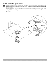
... the threads of the ball and socket mount to prevent any excess movement of the ceiling plate (G) and secure ball and socket mount (A) with a M5 x 10 mm socket pin screw (C) using security allen wrench (B) as shown in detail 1. Do not overtighten screw; WOOD CEILING G A C A K NOTCH G DETAIL 1 Visit the NEC Web Site at www.necsam.com...
... the threads of the ball and socket mount to prevent any excess movement of the ceiling plate (G) and secure ball and socket mount (A) with a M5 x 10 mm socket pin screw (C) using security allen wrench (B) as shown in detail 1. Do not overtighten screw; WOOD CEILING G A C A K NOTCH G DETAIL 1 Visit the NEC Web Site at www.necsam.com...
NP216 : NP01UCM (ceiling mount) instructions
Page 8
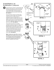
... top holes in extension column connector (I ) into slot in ball and socket mount (A) to extension column. overtightening screws will damage threads making it difficult to ceiling plate (G). See detail 4. Align slot in extension column connector (I COLUMN SLOT K A J DETAIL 6 Visit the NEC Web Site at www.necsam.com 8 of each connecting joint to jam...
... top holes in extension column connector (I ) into slot in ball and socket mount (A) to extension column. overtightening screws will damage threads making it difficult to ceiling plate (G). See detail 4. Align slot in extension column connector (I COLUMN SLOT K A J DETAIL 6 Visit the NEC Web Site at www.necsam.com 8 of each connecting joint to jam...
NP216 : NP01UCM (ceiling mount) instructions
Page 9
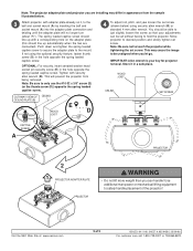
... it in appearance from being removed. This will no longer turn (about 75°). Move projector to the mount. IMPORTANT: Allen wrench is your adjustments can handle! Visit the NEC Web Site at www.necsam.com 9 of the projector! Note: Be sure to touch the projector while tightening...Note: The projector adapter plate and projector you are connected). The spring loaded captive screw should be set screw (shown below . CUTAWAY VIEW OF CEILING CEILING PLATE (G) E WOOD D JOIST To adjust roll, pitch, and yaw loosen the set without having to just slightly loosen the screw so that ...
... it in appearance from being removed. This will no longer turn (about 75°). Move projector to the mount. IMPORTANT: Allen wrench is your adjustments can handle! Visit the NEC Web Site at www.necsam.com 9 of the projector! Note: Be sure to touch the projector while tightening...Note: The projector adapter plate and projector you are connected). The spring loaded captive screw should be set screw (shown below . CUTAWAY VIEW OF CEILING CEILING PLATE (G) E WOOD D JOIST To adjust roll, pitch, and yaw loosen the set without having to just slightly loosen the screw so that ...

Whitepaper Projector Placement Comparison
Page 1
... the projectors are placed at the proper height (using 100" screen) and are within the zoom range for a 100" screen. Ver. 4.4 Ceiling Mounted Installation Ceiling Top Color Chart Red = M260X/260W/300X/300W, NP610/510/NP510W/NP410/NP410W/NP310, NP901W/NP905 Blue = NP1150/NP2150/NP3150/NP3151W, NP3250/NP3250W...is usually desired; Note: All projectors shown at for that lens. This drawing allows you to see the height each model needs to be mounted at the middle point of 2 www.necdisplay.com PJ Placement Page 1 of their respective zoom range. The ability to compare placement between ...
... the projectors are placed at the proper height (using 100" screen) and are within the zoom range for a 100" screen. Ver. 4.4 Ceiling Mounted Installation Ceiling Top Color Chart Red = M260X/260W/300X/300W, NP610/510/NP510W/NP410/NP410W/NP310, NP901W/NP905 Blue = NP1150/NP2150/NP3150/NP3151W, NP3250/NP3250W...is usually desired; Note: All projectors shown at for that lens. This drawing allows you to see the height each model needs to be mounted at the middle point of 2 www.necdisplay.com PJ Placement Page 1 of their respective zoom range. The ability to compare placement between ...
Specification Brochure
Page 2
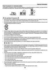
... control, batteries, RGB cable, power cord, user's manual, product registration card ORDERING MODEL NUMBERS NP-VE281 NP-VE281X Specifications for one year of text information from Texas Instruments delivers more vibrant and realistic colors and blacks richer with NEC ceiling mounts Component video adapter converts component video to D-sub 15-pin Power cable RGB cable Extends...
... control, batteries, RGB cable, power cord, user's manual, product registration card ORDERING MODEL NUMBERS NP-VE281 NP-VE281X Specifications for one year of text information from Texas Instruments delivers more vibrant and realistic colors and blacks richer with NEC ceiling mounts Component video adapter converts component video to D-sub 15-pin Power cable RGB cable Extends...
Users Manual
Page 5
Do not attempt to use any power cords than the desktop and ceiling mount, otherwise lamp life could decrease dramatically. 5˚ Fire and Shock Precautions • Ensure that there is damaged or frayed. - Ensure that your hands burned from ...
Do not attempt to use any power cords than the desktop and ceiling mount, otherwise lamp life could decrease dramatically. 5˚ Fire and Shock Precautions • Ensure that there is damaged or frayed. - Ensure that your hands burned from ...

Users Manual
Page 86
...Screen size: inch Screen type: White matte Beads Polarization Wide angle High contrast Throw distance: feet/inch/m Orientation: Ceiling mount Desktop Power outlet connection: Connected directly to wall outlet Connected to power cord extender or other (the number of connected...equipment Computer Manufacturer: Model number: Notebook PC / Desktop Native resolution: Refresh rate: Video adapter: Other: DVD player Signal cable NEC standard or other Manufacturer: Model number: 77 Model number: Length: inch/m Distribution amplifier Model number: Switcher Model number: Adapter...
...Screen size: inch Screen type: White matte Beads Polarization Wide angle High contrast Throw distance: feet/inch/m Orientation: Ceiling mount Desktop Power outlet connection: Connected directly to wall outlet Connected to power cord extender or other (the number of connected...equipment Computer Manufacturer: Model number: Notebook PC / Desktop Native resolution: Refresh rate: Video adapter: Other: DVD player Signal cable NEC standard or other Manufacturer: Model number: 77 Model number: Length: inch/m Distribution amplifier Model number: Switcher Model number: Adapter...

Installation Guide
Page 1
... calculations are based on the following page. www.necdisplay.com VE281/VE281X/VE282B/VE282XB Page 1 of America, Inc. NEC Display Solutions of 8 VE281/VE281X/VE282B/VE282XB Installation Guide Ceiling and Desktop Mounted Rev 1.0 Contents Product Description, Lens Specs, Notes Formulas Diagrams & Distance Charts Cabinet Dimensions Ceiling Mount Dimensions Input Panels and Control Codes Pg 1 Pg 2-3 Pg 4 Pg...
... calculations are based on the following page. www.necdisplay.com VE281/VE281X/VE282B/VE282XB Page 1 of America, Inc. NEC Display Solutions of 8 VE281/VE281X/VE282B/VE282XB Installation Guide Ceiling and Desktop Mounted Rev 1.0 Contents Product Description, Lens Specs, Notes Formulas Diagrams & Distance Charts Cabinet Dimensions Ceiling Mount Dimensions Input Panels and Control Codes Pg 1 Pg 2-3 Pg 4 Pg...
Installation Guide
Page 3
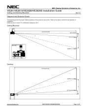
For millimeters multiply by 25.4. Ceiling Mounted Desktop www.necdisplay.com VE281/VE281X/VE282B/VE282XB Page 3 of the projector and screen. Distances are in inches. VE281/VE281X/VE282B/VE282XB Installation Guide Ceiling and Desktop Mounted Rev 1.0 Diagrams and Distance Charts The following shows the proper relative positions of 8 NEC Display Solutions of installation. Refer to the table to determine the position of America, Inc.
For millimeters multiply by 25.4. Ceiling Mounted Desktop www.necdisplay.com VE281/VE281X/VE282B/VE282XB Page 3 of the projector and screen. Distances are in inches. VE281/VE281X/VE282B/VE282XB Installation Guide Ceiling and Desktop Mounted Rev 1.0 Diagrams and Distance Charts The following shows the proper relative positions of 8 NEC Display Solutions of installation. Refer to the table to determine the position of America, Inc.
Installation Guide
Page 5
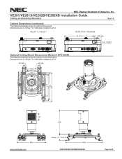
VE281/VE281X/VE282B/VE282XB Installation Guide Ceiling and Desktop Mounted Rev 1.0 Cabinet Dimensions (continued) The following drawings show the cabinet dimensions. Optional Ceiling Mount Dimensions (Model #: NP01UCM) The following drawings show the ceiling mount dimensions. For millimeters multiply by 25.4. Dimensions are in inches. For millimeters multiply by 25.4. NEC Display Solutions of 8 www.necdisplay.com VE281/VE281X/VE282B/VE282XB Page 5 of America, Inc. Dimensions are in inches.
VE281/VE281X/VE282B/VE282XB Installation Guide Ceiling and Desktop Mounted Rev 1.0 Cabinet Dimensions (continued) The following drawings show the cabinet dimensions. Optional Ceiling Mount Dimensions (Model #: NP01UCM) The following drawings show the ceiling mount dimensions. For millimeters multiply by 25.4. Dimensions are in inches. For millimeters multiply by 25.4. NEC Display Solutions of 8 www.necdisplay.com VE281/VE281X/VE282B/VE282XB Page 5 of America, Inc. Dimensions are in inches.
Mechanical Drawing
Page 1
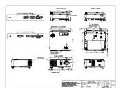
...1100 Telephone: Z63d467-3CCO VE281X/VE281 INPUT PANEL CEMN, 0 EEO 0 EXHAUST VE282X/VE282 8.35 1 .88 0 10.24 .D00 0) VE281X/VE281 o r=1 \jo amo o@wit))_ 0.75 3 - M4 x 8mm FOR CEILING MOUNT UNIT 7.32 a 2....16 0 0 En O 0 ZOOM LEVER FOCUS RING LENS CENTER 8.07 2.178 L.r) 0.79 5.24 IR RECEIVER 1_, 3.1 1 1.10 g 5.24 CEO 0 CM= =I= =ID 01119•ZI.C. 011=0, lor C 1=1 0,1 THE INFORMATION AND DESIGNS CONTAINED IN THIS DRAWING ARE CONFIDENTIAL AND THE PROPRIETARY PROPERTY OF NEC...
...1100 Telephone: Z63d467-3CCO VE281X/VE281 INPUT PANEL CEMN, 0 EEO 0 EXHAUST VE282X/VE282 8.35 1 .88 0 10.24 .D00 0) VE281X/VE281 o r=1 \jo amo o@wit))_ 0.75 3 - M4 x 8mm FOR CEILING MOUNT UNIT 7.32 a 2....16 0 0 En O 0 ZOOM LEVER FOCUS RING LENS CENTER 8.07 2.178 L.r) 0.79 5.24 IR RECEIVER 1_, 3.1 1 1.10 g 5.24 CEO 0 CM= =I= =ID 01119•ZI.C. 011=0, lor C 1=1 0,1 THE INFORMATION AND DESIGNS CONTAINED IN THIS DRAWING ARE CONFIDENTIAL AND THE PROPRIETARY PROPERTY OF NEC...

