MM2000B : MM2000B User Manual
Page 2
... safety instructions are trademarks or registered trademarks of the FCC Rules. A damaged cord can damage internal components. • Do not place heavy objects on the top of time, disconnect the plug from power outlet. The information should be installed as a trademark of Silicon Optix Inc. • Windows is a Class A product. REFER SERVICING TO QUALIFIED SERVICE PERSONNEL. DO NOT USE...
... safety instructions are trademarks or registered trademarks of the FCC Rules. A damaged cord can damage internal components. • Do not place heavy objects on the top of time, disconnect the plug from power outlet. The information should be installed as a trademark of Silicon Optix Inc. • Windows is a Class A product. REFER SERVICING TO QUALIFIED SERVICE PERSONNEL. DO NOT USE...
MM2000B : MM2000B User Manual
Page 3
.... • When using a LAN cable: For safety, do not handle the parts on . After collecting the used product EU-wide legislation as below; Doing so may cause damage due to electrostatic discharge. • Do not use the handle of the interface board to unclear points, malfunctions and repairs of heat inside your used products, they can damage your PC card or LAN card. • Please...
.... • When using a LAN cable: For safety, do not handle the parts on . After collecting the used product EU-wide legislation as below; Doing so may cause damage due to electrostatic discharge. • Do not use the handle of the interface board to unclear points, malfunctions and repairs of heat inside your used products, they can damage your PC card or LAN card. • Please...

MM2000B : MM2000B User Manual
Page 9
... Switcher ...16 3-2. Specifications ...24 6-5. Making Connections ...10 2-2. Connecting the Supplied Power Cable ...15 3.Projecting an Image 16 3-1. Turning off the Switcher ...17 4.LCD Menu 18 4-1. List of Contents 1.Introduction 2 1-1. Compatible input signal list ...23 6-4. Cabinet Dimensions ...30 1 Connecting to Know Your Switcher ...4 2.Installation 10 2-1. Basic operation from LCD screen menu ...18 4-2. Getting to a Network ...14 2-6. Cleaning the Cabinet ...20 6.Appendix 21 6-1. Error code list ...22 6-3. What's in...
... Switcher ...16 3-2. Specifications ...24 6-5. Making Connections ...10 2-2. Connecting the Supplied Power Cable ...15 3.Projecting an Image 16 3-1. Turning off the Switcher ...17 4.LCD Menu 18 4-1. List of Contents 1.Introduction 2 1-1. Compatible input signal list ...23 6-4. Cabinet Dimensions ...30 1 Connecting to Know Your Switcher ...4 2.Installation 10 2-1. Basic operation from LCD screen menu ...18 4-2. Getting to a Network ...14 2-6. Cleaning the Cabinet ...20 6.Appendix 21 6-1. Error code list ...22 6-3. What's in...
MM2000B : MM2000B User Manual
Page 13
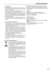
... mode. 2. Control Panel 1 1. A press of the Switcher during standby. POWER Indicator When this button to turn on ; BACK LIGHT Switch Use this indicator is orange, it is a fault. 9. when this switch to the last condition while you wish to adjust. ̇̈ : Use these buttons to exit "Menus". STATUS Indicator This indicates the status of the E button executes the selection. 8. Press this button for the service...
... mode. 2. Control Panel 1 1. A press of the Switcher during standby. POWER Indicator When this button to turn on ; BACK LIGHT Switch Use this indicator is orange, it is a fault. 9. when this switch to the last condition while you wish to adjust. ̇̈ : Use these buttons to exit "Menus". STATUS Indicator This indicates the status of the E button executes the selection. 8. Press this button for the service...
MM2000B : MM2000B User Manual
Page 14
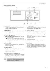
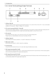
... extension. Main power switch Set the main power switch to "| (ON)" to a PC. 3. Use a commercially available DVI-D signal cable (single link). 8. USB port (type A) This terminal is for low 2-bit output of this unit in the wall outlet using a wireless LAN. AC IN terminal Connect the AC IN terminal of DVI. Control Terminals/Image Output Terminals 1 2 3 4 5 6 7 8 1. Use a commercially available RS-232C straight cable (male-female cable) to connect this terminal...
... extension. Main power switch Set the main power switch to "| (ON)" to a PC. 3. Use a commercially available DVI-D signal cable (single link). 8. USB port (type A) This terminal is for low 2-bit output of this unit in the wall outlet using a wireless LAN. AC IN terminal Connect the AC IN terminal of DVI. Control Terminals/Image Output Terminals 1 2 3 4 5 6 7 8 1. Use a commercially available RS-232C straight cable (male-female cable) to connect this terminal...

MM2000B : MM2000B User Manual
Page 15
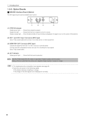
Make sure to mount the accessory ferrite clamp core to 4. Shows that this board is standard equipment. 4 2. The ferrite clamp core should be mounted as close to other equipment. (1) (2) (3) (1) RGB Input Connectors (5 BNC Type) Use a 75 Ω coaxial cable (5-conductor type) and connect it to the display output connector of the RGB signal cable. For removal and installation of the interface board, see...
Make sure to mount the accessory ferrite clamp core to 4. Shows that this board is standard equipment. 4 2. The ferrite clamp core should be mounted as close to other equipment. (1) (2) (3) (1) RGB Input Connectors (5 BNC Type) Use a 75 Ω coaxial cable (5-conductor type) and connect it to the display output connector of the RGB signal cable. For removal and installation of the interface board, see...
MM2000B : MM2000B User Manual
Page 16
... Connectors (BNC type) Use a 75 Ω coaxial cable and connect it for checking the input signal. NOTE Use the 75 Ω coaxial (5C-2V) cable or equivalent. Connect this board is displayed. TIP • For details about the compatible input signals, see page 23. • Cycle the unit power in the following cases. • The status indicator is lighting in orange. •...
... Connectors (BNC type) Use a 75 Ω coaxial cable and connect it for checking the input signal. NOTE Use the 75 Ω coaxial (5C-2V) cable or equivalent. Connect this board is displayed. TIP • For details about the compatible input signals, see page 23. • Cycle the unit power in the following cases. • The status indicator is lighting in orange. •...

MM2000B : MM2000B User Manual
Page 17
... of the graphics card resulting in no picture being displayed. If the signal cable has been disconnected and then re-connected, an image may not activate the digital output of a computer. (2) ACT Indicator Steady green light ....... NOTE • When Viewing a DVI Digital Signal: • Use the DVI-D signal cable compliant with DDWG (Digital Display Working Group) DVI...
... of the graphics card resulting in no picture being displayed. If the signal cable has been disconnected and then re-connected, an image may not activate the digital output of a computer. (2) ACT Indicator Steady green light ....... NOTE • When Viewing a DVI Digital Signal: • Use the DVI-D signal cable compliant with DDWG (Digital Display Working Group) DVI...

MM2000B : MM2000B User Manual
Page 18
... not disconnect the DVI-D signal cable while the Switcher is turned on your remote control, it may not be sure to connect between the Switcher and the notebook PC before turning on the power to the notebook PC. Installation 2-1. Making Connections NOTE When using with the Switcher. * If the screen goes blank while using a DVI-D signal cable before turning on your PC. When Viewing...
... not disconnect the DVI-D signal cable while the Switcher is turned on your remote control, it may not be sure to connect between the Switcher and the notebook PC before turning on the power to the notebook PC. Installation 2-1. Making Connections NOTE When using with the Switcher. * If the screen goes blank while using a DVI-D signal cable before turning on your PC. When Viewing...

MM2000B : MM2000B User Manual
Page 19
... well as shown below. Connecting Your Projector Connect this unit with the projector using two commercially available DVI-D signal cables. DVI OUT-B LAN DVI OUT-A LAN cross cable (not supplied) MM2000 DVI-D signal cable (not supplied) NC series projector DVI-A DVI-B LAN Touch panel controller (option) 11 2. Connect the DVI-D A input terminal (DVI-A) on the projector and the DVI OUT-A terminal on this unit using a LAN cable. Installation 2-2.
... well as shown below. Connecting Your Projector Connect this unit with the projector using two commercially available DVI-D signal cables. DVI OUT-B LAN DVI OUT-A LAN cross cable (not supplied) MM2000 DVI-D signal cable (not supplied) NC series projector DVI-A DVI-B LAN Touch panel controller (option) 11 2. Connect the DVI-D A input terminal (DVI-A) on the projector and the DVI OUT-A terminal on this unit using a LAN cable. Installation 2-2.

MM2000B : MM2000B User Manual
Page 20
... (supplied) BNC x 5 cable (not supplied) RCA(female)-to the cable. Installation 2-3. Cut off the surplus of the band to tighten it to -BNC(male) adapter (not supplied) Component video RCA x 3 cable (not supplied) PC Mounting the ferrite clamp core Use the supplied ferrite clamp core. See page 7. See page 13. Four interface boards can be inserted in the Switcher at the same time. When...
... (supplied) BNC x 5 cable (not supplied) RCA(female)-to the cable. Installation 2-3. Cut off the surplus of the band to tighten it to -BNC(male) adapter (not supplied) Component video RCA x 3 cable (not supplied) PC Mounting the ferrite clamp core Use the supplied ferrite clamp core. See page 7. See page 13. Four interface boards can be inserted in the Switcher at the same time. When...
MM2000B : MM2000B User Manual
Page 22
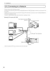
With a LAN cable connected, you can utilize the LAN environment. Connecting to a Network Connect various control terminals as standard equipment. Contact your dealer/distributor about use of the switcher in standalone mode. [Example of Connection with LAN] Touch panel controller (option) Server NC series projector Hub LAN cable* (not supplied) PC LAN PC MM2000 * When the switcher and PC are connected, use a mode for setting and adjustment of the switcher (standalone mode). Installation 2-5. The switcher is connected with a LAN port (RJ...
With a LAN cable connected, you can utilize the LAN environment. Connecting to a Network Connect various control terminals as standard equipment. Contact your dealer/distributor about use of the switcher in standalone mode. [Example of Connection with LAN] Touch panel controller (option) Server NC series projector Hub LAN cable* (not supplied) PC LAN PC MM2000 * When the switcher and PC are connected, use a mode for setting and adjustment of the switcher (standalone mode). Installation 2-5. The switcher is connected with a LAN port (RJ...

MM2000B : MM2000B User Manual
Page 23
... supplied power cable to the power cable. First connect the supplied power cable's three-pin plug to this unit as close to the AC IN of the Switcher, and then connect the other plug of the power cable. The ferrite clamp core should be mounted as possible. • Do not unplug the power cable from the wall outlet or switcher when the switcher is displayed on . 2. Make...
... supplied power cable to the power cable. First connect the supplied power cable's three-pin plug to this unit as close to the AC IN of the Switcher, and then connect the other plug of the power cable. The ferrite clamp core should be mounted as possible. • Do not unplug the power cable from the wall outlet or switcher when the switcher is displayed on . 2. Make...
MM2000B : MM2000B User Manual
Page 24
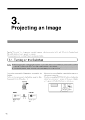
... the Main Power switch to the ON position ( I ). Standby Power ON POWER Steady orange light ON/STAND BY POWER Steady green light 16 Projecting an Image Specify "Title select" from the projector to project images of the projector connected to this unit are described below. 3-1. Turning on the Switcher NOTE • When plugging in or unplugging the supplied power cable, make sure that...
... the Main Power switch to the ON position ( I ). Standby Power ON POWER Steady orange light ON/STAND BY POWER Steady green light 16 Projecting an Image Specify "Title select" from the projector to project images of the projector connected to this unit are described below. 3-1. Turning on the Switcher NOTE • When plugging in or unplugging the supplied power cable, make sure that...
MM2000B : MM2000B User Manual
Page 25
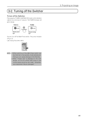
... glow orange. NOTE • When switching off the main power or pull out the power plug from the outlet. Last unplug the power cable. 3-2. Turning off the Switcher To turn off the Switcher: First press the POWER (ON/STAND BY) button on Standby POWER Steady green light ON/STAND BY POWER Steady orange light Second, turn off the Main Power switch, set the Switcher to the Switcher...
... glow orange. NOTE • When switching off the main power or pull out the power plug from the outlet. Last unplug the power cable. 3-2. Turning off the Switcher To turn off the Switcher: First press the POWER (ON/STAND BY) button on Standby POWER Steady green light ON/STAND BY POWER Steady orange light Second, turn off the Main Power switch, set the Switcher to the Switcher...

MM2000B : MM2000B User Manual
Page 27
... the SELECT ̇̈ button. Every time the SELECT ̄ button is the screen when power has been turned on the unit (See page 16). 4. List of input signal. Description Displays the selected slot number, the board name, and type of LCD screen menus Input Source Information Menu Version IP Address Error Code BIOS Firmware Data FPGA Serial No. Displays the Serial number of the switcher. Displays...
... the SELECT ̇̈ button. Every time the SELECT ̄ button is the screen when power has been turned on the unit (See page 16). 4. List of input signal. Description Displays the selected slot number, the board name, and type of LCD screen menus Input Source Information Menu Version IP Address Error Code BIOS Firmware Data FPGA Serial No. Displays the Serial number of the switcher. Displays...
MM2000B : MM2000B User Manual
Page 29
... blink or color display way be corrected, please contact your connection, settings and operation once again. page page 15 page 16 - For RGB (computer) input, is on the setting of the PC. Troubleshooting Before asking for repair, please check your dealer/distributor for current signal. If the trouble cannot be shifted in the following pages. Check that the main power switch...
... blink or color display way be corrected, please contact your connection, settings and operation once again. page page 15 page 16 - For RGB (computer) input, is on the setting of the PC. Troubleshooting Before asking for repair, please check your dealer/distributor for current signal. If the trouble cannot be shifted in the following pages. Check that the main power switch...
MM2000B : MM2000B User Manual
Page 30
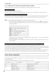
..., stop simultaneous display of the laptop, and set it is started before connecting the device. Error code 130 131 132 22 Error message MMS Comm Fail MMS Fan Stop MMS Fail : FPGA *** MMS Fail : Default Data MMS Fail : User Data Description Communication error with MMS MM2000 fan stopped MMS system error MMS system data error MMS user region error Timing for only external signals (in the table, refer to...
..., stop simultaneous display of the laptop, and set it is started before connecting the device. Error code 130 131 132 22 Error message MMS Comm Fail MMS Fan Stop MMS Fail : FPGA *** MMS Fail : Default Data MMS Fail : User Data Description Communication error with MMS MM2000 fan stopped MMS system error MMS system data error MMS user region error Timing for only external signals (in the table, refer to...
MM2000B : MM2000B User Manual
Page 32
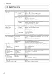
... OUT-A, DVI OUT-B) A Type x1 (For service personnel) RJ-45 x 1 D-Sub 9 pin x 1 (For service personnel) Input / Output Terminals 24 Specifications Model Number Image Input Image Input (Optional board specifications) Image output Image signal processing Input Slot MM-VIDEO (Standard board) MM-RGB (Standard board) MM-DVI (Option board) MM-SDI (Option board) Output Terminal USB Port LAN Port PC Control Terminal VIDEO RGB...
... OUT-A, DVI OUT-B) A Type x1 (For service personnel) RJ-45 x 1 D-Sub 9 pin x 1 (For service personnel) Input / Output Terminals 24 Specifications Model Number Image Input Image Input (Optional board specifications) Image output Image signal processing Input Slot MM-VIDEO (Standard board) MM-RGB (Standard board) MM-DVI (Option board) MM-SDI (Option board) Output Terminal USB Port LAN Port PC Control Terminal VIDEO RGB...
MM2000B : MM2000B User Manual
Page 33
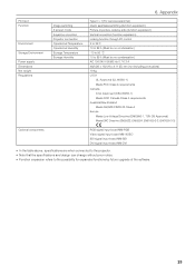
PC Card Function Environment Storage Environment Power supply Dimensions Net weight Regulations Image switching 2 screen mode Keystone correction Projector connection Operational Temperature Operational Humidity Storage Temperature Storage Humidity 6. Appendix Type II x 1 (For service personnel) Quick seamless switching (function expansion) Picture-in-picture, side-by-side (function expansion) Vertical correction (function expansion) Linking function through PC control 5 to 35˚C 10 to 85% (Must...
PC Card Function Environment Storage Environment Power supply Dimensions Net weight Regulations Image switching 2 screen mode Keystone correction Projector connection Operational Temperature Operational Humidity Storage Temperature Storage Humidity 6. Appendix Type II x 1 (For service personnel) Quick seamless switching (function expansion) Picture-in-picture, side-by-side (function expansion) Vertical correction (function expansion) Linking function through PC control 5 to 35˚C 10 to 85% (Must...