MM2000B : MM2000B User Manual
Page 2
... attached. Record it is registered in which case the user will be sufficient to comply with any interference with radio and television reception use your supplier. • DLP, DLP Cinema and their respective holders. If a power cable is not supplied with the installation manual, may be required to make any kind of Texas Instruments. • HQV logo is...
... attached. Record it is registered in which case the user will be sufficient to comply with any interference with radio and television reception use your supplier. • DLP, DLP Cinema and their respective holders. If a power cable is not supplied with the installation manual, may be required to make any kind of Texas Instruments. • HQV logo is...
MM2000B : MM2000B User Manual
Page 3
...: +44 1952 237000 Fax Line: +44 1952 237006 In North America NEC Corporation of heat inside your bare hands. Important Information CAUTION • When switching off the Main Power switch, set the Switcher to the current European Union Member States. Doing so can become heated while the switcher is turned on the interface board with your switcher. Doing...
...: +44 1952 237000 Fax Line: +44 1952 237006 In North America NEC Corporation of heat inside your bare hands. Important Information CAUTION • When switching off the Main Power switch, set the Switcher to the current European Union Member States. Doing so can become heated while the switcher is turned on the interface board with your switcher. Doing...

MM2000B : MM2000B User Manual
Page 9
... 4.LCD Menu 18 4-1. Compatible input signal list ...23 6-4. Cleaning the Cabinet ...20 6.Appendix 21 6-1. Error code list ...22 6-3. Connecting to Know Your Switcher ...4 2.Installation 10 2-1. Connecting the Supplied Power Cable ...15 3.Projecting an Image 16 3-1. Basic operation from LCD screen menu ...18 4-2. Troubleshooting ...21 6-2. Making Connections ...10 2-2. Turning on the Switcher ...16 3-2. Specifications ...24 6-5. What's in the Box? ...3 1-3. Connecting to a Network ...14 2-6. Cabinet Dimensions ...30 1 List of Contents 1.Introduction...
... 4.LCD Menu 18 4-1. Compatible input signal list ...23 6-4. Cleaning the Cabinet ...20 6.Appendix 21 6-1. Error code list ...22 6-3. Connecting to Know Your Switcher ...4 2.Installation 10 2-1. Connecting the Supplied Power Cable ...15 3.Projecting an Image 16 3-1. Basic operation from LCD screen menu ...18 4-2. Troubleshooting ...21 6-2. Making Connections ...10 2-2. Turning on the Switcher ...16 3-2. Specifications ...24 6-5. What's in the Box? ...3 1-3. Connecting to a Network ...14 2-6. Cabinet Dimensions ...30 1 List of Contents 1.Introduction...
MM2000B : MM2000B User Manual
Page 13
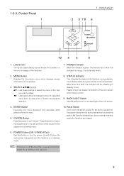
... screen. 4. Reset Switch Don't touch this switch to exit "Menus". 1-3-3. NOTE To turn on the back light of 1 second. 5 SELECT ̆̄ : Use these buttons to turn on or off when the main power is supplied and the Switcher is in the adjustment or setting menu. 10. CANCEL Button Press this button to change the level of a setup inside the Switcher are in standby mode. POWER Button (ON...
... screen. 4. Reset Switch Don't touch this switch to exit "Menus". 1-3-3. NOTE To turn on the back light of 1 second. 5 SELECT ̆̄ : Use these buttons to turn on or off when the main power is supplied and the Switcher is in the adjustment or setting menu. 10. CANCEL Button Press this button to change the level of a setup inside the Switcher are in standby mode. POWER Button (ON...
MM2000B : MM2000B User Manual
Page 14
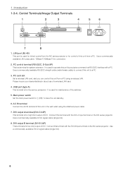
... DVI-A input terminal on the NC series projector. Use a commercially available DVI-D signal cable (single link). 6 Main power switch Set the main power switch to "| (ON)" to operate this unit from a PC using the attached power cable. 7. Use a commercially available DVI-D signal cable (single link). 8. LAN port (RJ-45) This port is used to have the unit standby. 6. PC card slot Set a wireless LAN card, and you can control this terminal with the DVI-B input...
... DVI-A input terminal on the NC series projector. Use a commercially available DVI-D signal cable (single link). 6 Main power switch Set the main power switch to "| (ON)" to operate this unit from a PC using the attached power cable. 7. Use a commercially available DVI-D signal cable (single link). 8. LAN port (RJ-45) This port is used to have the unit standby. 6. PC card slot Set a wireless LAN card, and you can control this terminal with the DVI-B input...

MM2000B : MM2000B User Manual
Page 15
... Input Connectors (3 BNC Type) Use a 75 Ω coaxial cable (3-conductor type) and connect it to the display output connector of a DVD player, or to other equipment. (2) Audio Input Jacks (RCA-Phono) These Jacks have no function with the Switcher. (3) ACT Indicator Steady green light ........ See page 13. 4. See page 13. Make sure to mount the accessory ferrite clamp...
... Input Connectors (3 BNC Type) Use a 75 Ω coaxial cable (3-conductor type) and connect it to the display output connector of a DVD player, or to other equipment. (2) Audio Input Jacks (RCA-Phono) These Jacks have no function with the Switcher. (3) ACT Indicator Steady green light ........ See page 13. 4. See page 13. Make sure to mount the accessory ferrite clamp...
MM2000B : MM2000B User Manual
Page 16
... or cause no signal or an error occurs. Introduction 1-3-6. Steady red light Shows that this with a dedicated monitor and use it to turn on the power of the switcher. (2) SDI 1 and SDI 2 Input Connectors (BNC type) Use a 75 Ω coaxial cable and connect it for checking the input signal. Use a 75 Ω coaxial cable. (4) ACT Indicator Steady green light ....... Shows that there is not...
... or cause no signal or an error occurs. Introduction 1-3-6. Steady red light Shows that this with a dedicated monitor and use it to turn on the power of the switcher. (2) SDI 1 and SDI 2 Input Connectors (BNC type) Use a 75 Ω coaxial cable and connect it for checking the input signal. Use a 75 Ω coaxial cable. (4) ACT Indicator Steady green light ....... Shows that there is not...

MM2000B : MM2000B User Manual
Page 17
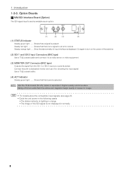
...Use the DVI-D signal cable compliant with DDWG (Digital Display Working Group) DVI (Digital Visual Interface) revision 1.0 standard. Should this happen, restart your PC. Introduction (1) (2) (1) DVI-D Input Connector (DVI-D 24 Pin) Use a DVI-D Signal cable and connect it to connect the PC and the Switcher using a DVI-D signal cable before turning ... source menu before turning on your PC. • Do not disconnect the DVI-D signal cable while the Switcher is running. Failure to do so may not be sure to the DVI output connector of the graphics card resulting in no ...
...Use the DVI-D signal cable compliant with DDWG (Digital Display Working Group) DVI (Digital Visual Interface) revision 1.0 standard. Should this happen, restart your PC. Introduction (1) (2) (1) DVI-D Input Connector (DVI-D 24 Pin) Use a DVI-D Signal cable and connect it to connect the PC and the Switcher using a DVI-D signal cable before turning ... source menu before turning on your PC. • Do not disconnect the DVI-D signal cable while the Switcher is running. Failure to do so may not be sure to the DVI output connector of the graphics card resulting in no ...

MM2000B : MM2000B User Manual
Page 18
.... 10 Making Connections NOTE When using with the Switcher. * If the screen goes blank while using a DVI-D signal cable before turning on the power to do so may not activate the digital output of the computer's screen-saver or power management software. Should this happen, restart your PC. Installation 2-1. Turn on after connecting with a notebook PC, be the result of the graphics card resulting...
.... 10 Making Connections NOTE When using with the Switcher. * If the screen goes blank while using a DVI-D signal cable before turning on the power to do so may not activate the digital output of the computer's screen-saver or power management software. Should this happen, restart your PC. Installation 2-1. Turn on after connecting with a notebook PC, be the result of the graphics card resulting...

MM2000B : MM2000B User Manual
Page 19
... series projector DVI-A DVI-B LAN Touch panel controller (option) 11 Connecting Your Projector Connect this unit and the projector as the DVI-D B input terminal (DVI-B) on the projector and the DVI OUT-B terminal on this unit with the projector using two commercially available DVI-D signal cables. 2. Alternatively, when a mode to control this unit from the projector (linked mode) is used, connect this unit using a LAN cable. Installation...
... series projector DVI-A DVI-B LAN Touch panel controller (option) 11 Connecting Your Projector Connect this unit and the projector as the DVI-D B input terminal (DVI-B) on the projector and the DVI OUT-B terminal on this unit with the projector using two commercially available DVI-D signal cables. 2. Alternatively, when a mode to control this unit from the projector (linked mode) is used, connect this unit using a LAN cable. Installation...
MM2000B : MM2000B User Manual
Page 22
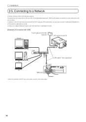
... are connected, use the LAN cross cable. 14 In addition, when the switcher is provided with a LAN port (RJ-45) as required. With a LAN cable connected, you can use of the switcher in standalone mode. [Example of the switcher (standalone mode). Contact your dealer/distributor about use a mode for setting and adjustment of Connection with a PC using a LAN cross cable, you can utilize the LAN environment. 2. Connecting to a Network Connect various control terminals as standard equipment. Installation 2-5.
... are connected, use the LAN cross cable. 14 In addition, when the switcher is provided with a LAN port (RJ-45) as required. With a LAN cable connected, you can use of the switcher in standalone mode. [Example of the switcher (standalone mode). Contact your dealer/distributor about use a mode for setting and adjustment of Connection with a PC using a LAN cross cable, you can utilize the LAN environment. 2. Connecting to a Network Connect various control terminals as standard equipment. Installation 2-5.

MM2000B : MM2000B User Manual
Page 23
... connect the supplied power cable's three-pin plug to the AC IN of the Switcher, and then connect the other plug of the power cable. Make sure that the prongs are fully inserted into both the AC IN and the wall outlet Ferrite clamp core (supplied) NOTE • Always mount the ferrite clamp core to this unit as close to the power cable...
... connect the supplied power cable's three-pin plug to the AC IN of the Switcher, and then connect the other plug of the power cable. Make sure that the prongs are fully inserted into both the AC IN and the wall outlet Ferrite clamp core (supplied) NOTE • Always mount the ferrite clamp core to this unit as close to the power cable...
MM2000B : MM2000B User Manual
Page 24
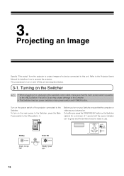
... to the Projector User's Manual for a minimum of a device connected to use. To turn on . The procedures to the off this unit. Turning on the Switcher NOTE • When plugging in or unplugging the supplied power cable, make sure that the computer or video source is pushed to turn on the Switcher cabinet for details on the power switch of the projector connected to the...
... to the Projector User's Manual for a minimum of a device connected to use. To turn on . The procedures to the off this unit. Turning on the Switcher NOTE • When plugging in or unplugging the supplied power cable, make sure that the computer or video source is pushed to turn on the Switcher cabinet for details on the power switch of the projector connected to the...
MM2000B : MM2000B User Manual
Page 25
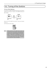
... the power cable. Turning off the Switcher To turn off the Switcher: First press the POWER (ON/STAND BY) button on Standby POWER Steady green light ON/STAND BY POWER Steady orange light Second, turn off the Main Power switch. Doing so can cause damage to the Switcher. • When "Please wait" is displayed in the LDC screen, do not turn off the Main Power switch, set...
... the power cable. Turning off the Switcher To turn off the Switcher: First press the POWER (ON/STAND BY) button on Standby POWER Steady green light ON/STAND BY POWER Steady orange light Second, turn off the Main Power switch. Doing so can cause damage to the Switcher. • When "Please wait" is displayed in the LDC screen, do not turn off the Main Power switch, set...

MM2000B : MM2000B User Manual
Page 27
..., the display returns to the previous status. * This is displayed. 5 Press the SELECT ̄ button for several times. Displays the data version of the switcher. Displays the Serial number of LCD screen menus Input Source Information Menu Version IP Address Error Code BIOS Firmware Data FPGA Serial No. Displays the currently occurring error. 19 LCD Menu 1 Press the MENU button. List of the switcher. As you...
..., the display returns to the previous status. * This is displayed. 5 Press the SELECT ̄ button for several times. Displays the data version of the switcher. Displays the Serial number of LCD screen menus Input Source Information Menu Version IP Address Error Code BIOS Firmware Data FPGA Serial No. Displays the currently occurring error. 19 LCD Menu 1 Press the MENU button. List of the switcher. As you...
MM2000B : MM2000B User Manual
Page 29
... power switch on . Use the menus or Source/Input button on the remote control to select the source you want to see the following cases depending on No picture Image is scrolling vertically, horizontally or both Cross color in RGB mode Check These Items Check that the power cable is it a resolution and frequency supported by the input signals? Troubleshooting Before asking for repair...
... power switch on . Use the menus or Source/Input button on the remote control to select the source you want to see the following cases depending on No picture Image is scrolling vertically, horizontally or both Cross color in RGB mode Check These Items Check that the power cable is it a resolution and frequency supported by the input signals? Troubleshooting Before asking for repair...
MM2000B : MM2000B User Manual
Page 30
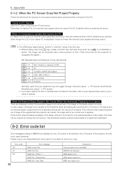
... press the key will be output if the PC is started before connecting the device. Error code 130 131 132 22 Error message MMS Comm Fail MMS Fan Stop MMS Fail : FPGA *** MMS Fail : Default Data MMS Fail : User Data Description Communication error with MMS MM2000 fan stopped MMS system error MMS system data error MMS user region error 6. Appendix 6-1-2. When it does not mean that external output signals...
... press the key will be output if the PC is started before connecting the device. Error code 130 131 132 22 Error message MMS Comm Fail MMS Fan Stop MMS Fail : FPGA *** MMS Fail : Default Data MMS Fail : User Data Description Communication error with MMS MM2000 fan stopped MMS system error MMS system data error MMS user region error 6. Appendix 6-1-2. When it does not mean that external output signals...
MM2000B : MM2000B User Manual
Page 32
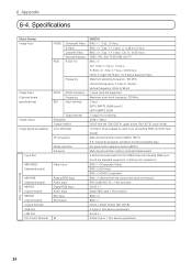
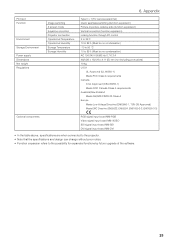
6. Specifications Model Number Image Input Image Input (Optional board specifications) Image output Image signal processing Input Slot MM-VIDEO (Standard board) MM-RGB (Standard board) MM-DVI (Option board) MM-SDI (Option board) Output Terminal USB Port LAN Port PC Control Terminal VIDEO RGB Composite Video S-Video ... linkʢDVI OUT-A: upper 8-bits, DVI OUT-B: lower 2-bitsʣ 10 bits for all processes for each color (excluding RGB, and DVI input board) Multi-directional filter method (SDTV, HDTV) 3:2, 2:2 pull down signal, animation format compatible type Per-pixel motion adaptive ...
6. Specifications Model Number Image Input Image Input (Optional board specifications) Image output Image signal processing Input Slot MM-VIDEO (Standard board) MM-RGB (Standard board) MM-DVI (Option board) MM-SDI (Option board) Output Terminal USB Port LAN Port PC Control Terminal VIDEO RGB Composite Video S-Video ... linkʢDVI OUT-A: upper 8-bits, DVI OUT-B: lower 2-bitsʣ 10 bits for all processes for each color (excluding RGB, and DVI input board) Multi-directional filter method (SDTV, HDTV) 3:2, 2:2 pull down signal, animation format compatible type Per-pixel motion adaptive ...
MM2000B : MM2000B User Manual
Page 33
... the table above, specifications are when connected to the projector. • Note that the specifications and design can change without prior notice. • Function expansion refers to the possibility for expanded functions by future upgrade of the software. 25 PC Card Function Environment Storage Environment Power supply Dimensions Net weight Regulations Image switching 2 screen mode Keystone correction Projector connection Operational Temperature Operational...
... the table above, specifications are when connected to the projector. • Note that the specifications and design can change without prior notice. • Function expansion refers to the possibility for expanded functions by future upgrade of the software. 25 PC Card Function Environment Storage Environment Power supply Dimensions Net weight Regulations Image switching 2 screen mode Keystone correction Projector connection Operational Temperature Operational...
MM2000 : Alternative Content Processors Brochure
Page 1
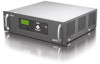
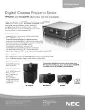
... MM2000 is compatible with the NC2500S-A and NC1600C-A. NEC Display Solutions 500 Park Boulevard, Suite 1100 Itasca, IL 60143 866-NEC-MORE Product specifications subject to computer presentations. Digital Cinema Projectors Digital Cinema Projector Series MM2000 and MM2000B alternative content processors Ideal as an independent unit (MM2000) or as a built-in MM2000B is available only with all models of the NEC...
... MM2000 is compatible with the NC2500S-A and NC1600C-A. NEC Display Solutions 500 Park Boulevard, Suite 1100 Itasca, IL 60143 866-NEC-MORE Product specifications subject to computer presentations. Digital Cinema Projectors Digital Cinema Projector Series MM2000 and MM2000B alternative content processors Ideal as an independent unit (MM2000) or as a built-in MM2000B is available only with all models of the NEC...