Quick Reference Guide
Page 2
... license exists only for equipment, circuits, and subsystems contained in connection with, the application or use of , or in Motorola products. Motorola, Inc. One Motorola Plaza Holtsville, N.Y. 11742-1300 http://www.symbol.com Warranty For the complete Motorola hardware product warranty statement, go to improve reliability, function, or design. 2 RS409 Ring Scanner © 2007 MOTOROLA, INC. Motorola does not assume any product to : http://www.symbol.com/patents.
... license exists only for equipment, circuits, and subsystems contained in connection with, the application or use of , or in Motorola products. Motorola, Inc. One Motorola Plaza Holtsville, N.Y. 11742-1300 http://www.symbol.com Warranty For the complete Motorola hardware product warranty statement, go to improve reliability, function, or design. 2 RS409 Ring Scanner © 2007 MOTOROLA, INC. Motorola does not assume any product to : http://www.symbol.com/patents.
Quick Reference Guide
Page 3
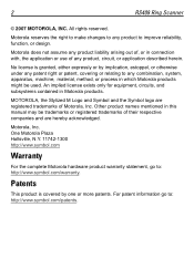
... Window Scan Assembly Scan LED Trigger Assembly Finger Strap Assembly Scan Trigger The RS409 is available in two configurations; Quick Reference Guide 3 Introduction The RS409 ring scanner is used with the WT4070/90 wearable terminal. The scanner is a modular, wearable laser scanner that allows the operator hands-free bar code scanning capability. a short cable version for connection to a wrist mounted wearable terminal, and a long cable version for connection to the wearable terminal, which provides power and performs the data...
... Window Scan Assembly Scan LED Trigger Assembly Finger Strap Assembly Scan Trigger The RS409 is available in two configurations; Quick Reference Guide 3 Introduction The RS409 ring scanner is used with the WT4070/90 wearable terminal. The scanner is a modular, wearable laser scanner that allows the operator hands-free bar code scanning capability. a short cable version for connection to a wrist mounted wearable terminal, and a long cable version for connection to the wearable terminal, which provides power and performs the data...
Quick Reference Guide
Page 4
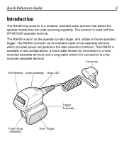
Determine whether the RS409 is positioned next to provide left hand. Do not rotate the trigger assembly past the designed stops. 2. 4 RS409 Ring Scanner Changing Trigger Position The trigger assembly of the scan assembly. Rotate the trigger assembly so that the scan trigger is used on the index finger. CAUTION The trigger assembly only rotates 180° around the back of the RS409 rotates to the thumb when the RS409 is placed on the right or left -hand or right-hand use. 1.
Determine whether the RS409 is positioned next to provide left hand. Do not rotate the trigger assembly past the designed stops. 2. 4 RS409 Ring Scanner Changing Trigger Position The trigger assembly of the scan assembly. Rotate the trigger assembly so that the scan trigger is used on the index finger. CAUTION The trigger assembly only rotates 180° around the back of the RS409 rotates to the thumb when the RS409 is placed on the right or left -hand or right-hand use. 1.
Quick Reference Guide
Page 5
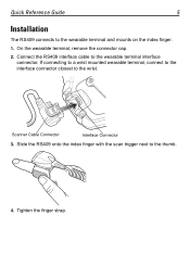
If connecting to a wrist mounted wearable terminal, connect to the interface connector closest to the wearable terminal and mounts on the index finger. 1. Tighten the finger strap. Scanner Cable Connector Interface Connector 3. Quick Reference Guide 5 Installation The RS409 connects to the wrist. On the wearable terminal, remove the connector cap. 2. Slide the RS409 onto the index finger with the scan trigger next to the wearable terminal interface connector. Connect the RS409 interface cable to the thumb. 4.
If connecting to a wrist mounted wearable terminal, connect to the interface connector closest to the wearable terminal and mounts on the index finger. 1. Tighten the finger strap. Scanner Cable Connector Interface Connector 3. Quick Reference Guide 5 Installation The RS409 connects to the wrist. On the wearable terminal, remove the connector cap. 2. Slide the RS409 onto the index finger with the scan trigger next to the wearable terminal interface connector. Connect the RS409 interface cable to the thumb. 4.
Quick Reference Guide
Page 6
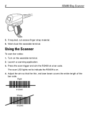
Using the Scanner To scan bar codes: 1. Warm boot the wearable terminal. The scan LED lights red to indicate the RS409 is on the wearable terminal. 2. Turn on . 4. Adjust the aim so that the thin, red laser beam covers the entire length of the bar code. Press the scan trigger and aim the RS409 at a bar code. Launch a scanning application. 3. If required, cut excess finger strap material. 6. Right 012345 Wrong 012345 6 RS409 Ring Scanner 5.
Using the Scanner To scan bar codes: 1. Warm boot the wearable terminal. The scan LED lights red to indicate the RS409 is on the wearable terminal. 2. Turn on . 4. Adjust the aim so that the thin, red laser beam covers the entire length of the bar code. Press the scan trigger and aim the RS409 at a bar code. Launch a scanning application. 3. If required, cut excess finger strap material. 6. Right 012345 Wrong 012345 6 RS409 Ring Scanner 5.
Quick Reference Guide
Page 7
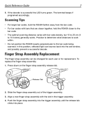
... release tab. If the decode is successful the LED turns green. Align a new finger strap assembly with bar code density, but 10 to 25 cm (4 to the bar code being scanned. Practice to determine what distances to work within. • Do not position the RS409 exactly perpendicular to 10 inches) generally works. In this position, reflected light can be changed for each user or for replacement. Release Tab 2. Quick Reference Guide...
... release tab. If the decode is successful the LED turns green. Align a new finger strap assembly with bar code density, but 10 to 25 cm (4 to the bar code being scanned. Practice to determine what distances to work within. • Do not position the RS409 exactly perpendicular to 10 inches) generally works. In this position, reflected light can be changed for each user or for replacement. Release Tab 2. Quick Reference Guide...
Quick Reference Guide
Page 8
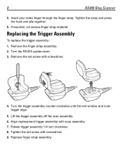
... the trigger assembly off the scan assembly. 6. Insert your index finger through the finger strap. If required, cut excess finger strap material. Remove the set screw with screwdriver. 9. Remove the finger strap assembly. 2. Turn the trigger assembly counter-clockwise until the exit window and scan trigger align. 5. Align replacement trigger assembly with screwdriver. 4. Tighten the set screw with scan assembly. 7. 8 RS409 Ring Scanner 5. Rotate trigger assembly 1/4 turn clockwise...
... the trigger assembly off the scan assembly. 6. Insert your index finger through the finger strap. If required, cut excess finger strap material. Remove the set screw with screwdriver. 9. Remove the finger strap assembly. 2. Turn the trigger assembly counter-clockwise until the exit window and scan trigger align. 5. Align replacement trigger assembly with screwdriver. 4. Tighten the set screw with scan assembly. 7. 8 RS409 Ring Scanner 5. Rotate trigger assembly 1/4 turn clockwise...
Quick Reference Guide
Page 9
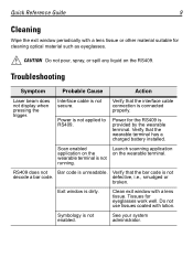
... work well. RS409 does not Bar code is not secure. Troubleshooting Symptom Probable Cause Action Laser beam does not display when pressing the trigger. Power is dirty. defective, i.e., smudged or broken. Verify that the interface cable connection is connected properly. Tissues for the RS409 is not decode a bar code. Verify that the bar code is provided by the wearable terminal. Launch scanning application on the wearable terminal is not enabled. Exit window...
... work well. RS409 does not Bar code is not secure. Troubleshooting Symptom Probable Cause Action Laser beam does not display when pressing the trigger. Power is dirty. defective, i.e., smudged or broken. Verify that the interface cable connection is connected properly. Tissues for the RS409 is not decode a bar code. Verify that the bar code is provided by the wearable terminal. Launch scanning application on the wearable terminal is not enabled. Exit window...
Quick Reference Guide
Page 10
... or eliminate direct pressure • Provide adequate clearance • Provide a suitable working environment • Improve work procedures. Please see the following website: http://www.symbol.com/manuals/ and look for your company's safety programs to avoid or minimize the potential risk of Motorola, Inc. ("Motorola"). All Symbol devices are designed to operate the equipment. Regulatory Information is approved under the...
... or eliminate direct pressure • Provide adequate clearance • Provide a suitable working environment • Improve work procedures. Please see the following website: http://www.symbol.com/manuals/ and look for your company's safety programs to avoid or minimize the potential risk of Motorola, Inc. ("Motorola"). All Symbol devices are designed to operate the equipment. Regulatory Information is approved under the...
Quick Reference Guide
Page 11
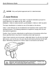
Quick Reference Guide 11 CAUTION Only use a low power, visible light diode. Class 1 Laser devices are not considered to be hazardous when used for deviations pursuant to comply with US and international regulations: Caution: Use of controls, adjustments or performance of the labels on one of procedures other than those specified herein may result in hazardous laser light exposure. Momentary exposure to a Class 2 laser is required...
Quick Reference Guide 11 CAUTION Only use a low power, visible light diode. Class 1 Laser devices are not considered to be hazardous when used for deviations pursuant to comply with US and international regulations: Caution: Use of controls, adjustments or performance of the labels on one of procedures other than those specified herein may result in hazardous laser light exposure. Momentary exposure to a Class 2 laser is required...

Quick Reference Guide
Page 12
... installed and used in accordance with the instructions, may be determined by turning the equipment off and on, the user is encouraged to try to correct the interference by one or more of the FCC rules. 12 RS409 Ring Scanner ...installation. Canada This Class B digital apparatus complies with Canadian ICES-003. These limits are designed to Part 15 of the following measures: • Reorient or relocate the receiving antenna • Increase the separation between the equipment and receiver • Connect the equipment into an outlet on a circuit different from http://www2.symbol.com...
... installed and used in accordance with the instructions, may be determined by turning the equipment off and on, the user is encouraged to try to correct the interference by one or more of the FCC rules. 12 RS409 Ring Scanner ...installation. Canada This Class B digital apparatus complies with Canadian ICES-003. These limits are designed to Part 15 of the following measures: • Reorient or relocate the receiving antenna • Increase the separation between the equipment and receiver • Connect the equipment into an outlet on a circuit different from http://www2.symbol.com...
Quick Reference Guide
Page 16
..., they will contact the Motorola Enterprise Mobility Support at: http://www.symbol.com/contactsupport. Patent and Trademark Office. October 2007 Motorola, Inc. Service Information If you have a problem using the equipment, contact your facility's Technical or Systems Support. All other product or service names are registered in the U.S. For the latest version of their respective owners. © Motorola, Inc. 2007 72-86010...
..., they will contact the Motorola Enterprise Mobility Support at: http://www.symbol.com/contactsupport. Patent and Trademark Office. October 2007 Motorola, Inc. Service Information If you have a problem using the equipment, contact your facility's Technical or Systems Support. All other product or service names are registered in the U.S. For the latest version of their respective owners. © Motorola, Inc. 2007 72-86010...


