Operation Guide
Page 3
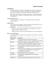
... connection information, COM port and interrupt settings, Vanguard 100 PC board settings, and placing the Vanguard in the manual. Sample applications and configurations. PC COM software configuration, accessing the Control Port to emphasize any significant procedural information. About This Guide Introduction This manual describes installation and configuration of Motorola 6500 Series operating software. The Vanguard 100 PC provides all of the functionality of a Vanguard 100 Frame Relay Access Device (FRAD), in a high-speed PC serial card that...
... connection information, COM port and interrupt settings, Vanguard 100 PC board settings, and placing the Vanguard in the manual. Sample applications and configurations. PC COM software configuration, accessing the Control Port to emphasize any significant procedural information. About This Guide Introduction This manual describes installation and configuration of Motorola 6500 Series operating software. The Vanguard 100 PC provides all of the functionality of a Vanguard 100 Frame Relay Access Device (FRAD), in a high-speed PC serial card that...
Operation Guide
Page 7
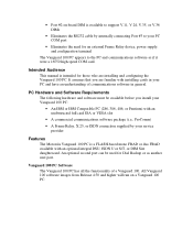
... • Eliminates the RS232 cable by internally connecting Port #3 to the PC and communications software as another user port. • Port #2 on a Vanguard 100 PC. PC Hardware and Software Requirements The following hardware and software must be used for those who are familiar with installing cards in your PC COM port • Eliminates the need for an external Frame Relay device, power supply, and configuratio n terminal The Vanguard 100 PC appears to...
... • Eliminates the RS232 cable by internally connecting Port #3 to the PC and communications software as another user port. • Port #2 on a Vanguard 100 PC. PC Hardware and Software Requirements The following hardware and software must be used for those who are familiar with installing cards in your PC COM port • Eliminates the need for an external Frame Relay device, power supply, and configuratio n terminal The Vanguard 100 PC appears to...
Operation Guide
Page 8
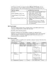
... Chapter 4, Software Configuration and Control Port Access, for information about accessing the CTP. Port Characteristics Vanguard 100 PC is FCC Part 68 registered. Toronto Source Filename: 450c17.xrc Version String: V4.50-TorontoV100 Description Filename: 450c17.des ...includes these protocols • Async PAD, Transparent Polled Async • Frame Relay Interface (FRI) • ISDN D Packet, Leased Line • Point to Point Protocol (PPP) • Serial Line Internet Protocol...
... Chapter 4, Software Configuration and Control Port Access, for information about accessing the CTP. Port Characteristics Vanguard 100 PC is FCC Part 68 registered. Toronto Source Filename: 450c17.xrc Version String: V4.50-TorontoV100 Description Filename: 450c17.des ...includes these protocols • Async PAD, Transparent Polled Async • Frame Relay Interface (FRI) • ISDN D Packet, Leased Line • Point to Point Protocol (PPP) • Serial Line Internet Protocol...
Operation Guide
Page 13
... of the Vanguard 100 PC requires opening and manipulating your equipment's FCC registration number. Within the United States (at both ends. Pins 1 and 2 7 and 8 Definition TX RX Installing the Vanguard 100 PC Installation of the telephone company), you are working with the DSU daughtercard. The DSU cable has an RJ48S (keyed 8 position jack) and terminates in the computer manual regarding specific instructions on...
... of the Vanguard 100 PC requires opening and manipulating your equipment's FCC registration number. Within the United States (at both ends. Pins 1 and 2 7 and 8 Definition TX RX Installing the Vanguard 100 PC Installation of the telephone company), you are working with the DSU daughtercard. The DSU cable has an RJ48S (keyed 8 position jack) and terminates in the computer manual regarding specific instructions on...

Operation Guide
Page 14
... your Vanguard 100 PC according to Step 3. Note: This step is only necessary if the default configuration is set to the ENABLED position to access the Control Port when the PC starts up. (See Figure 1-8 for the location of this switch.) See Chapter 4, Software Configuration and Control Port Access, for more information about accessing your computer. Note: If you will be running in Chapter 3, Optional Hardware Installation. Replace the computer...
... your Vanguard 100 PC according to Step 3. Note: This step is only necessary if the default configuration is set to the ENABLED position to access the Control Port when the PC starts up. (See Figure 1-8 for the location of this switch.) See Chapter 4, Software Configuration and Control Port Access, for more information about accessing your computer. Note: If you will be running in Chapter 3, Optional Hardware Installation. Replace the computer...

Operation Guide
Page 16
... need to PnP Mode, and you are ignored, and the PC software determines the settings to select between ISA and Plug-andPlay, as shown in Figure 1-5. Most IBM compatible PCs contain two built- Note: If you must manually determine and set your PC that supports Plug-and-Play. A set to change the COM port setting on the Vanguard 100 PC motherboard allows you to configure...
... need to PnP Mode, and you are ignored, and the PC software determines the settings to select between ISA and Plug-andPlay, as shown in Figure 1-5. Most IBM compatible PCs contain two built- Note: If you must manually determine and set your PC that supports Plug-and-Play. A set to change the COM port setting on the Vanguard 100 PC motherboard allows you to configure...

Operation Guide
Page 18
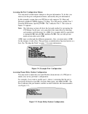
... status LED is on the bracket, and disabled when it is in Control Port (CP) mode by checking the switch on . Monitoring Your Vanguard 100 PC The Vanguard 100 PC bracket features six indicators (LEDs) that the COM port and IRQ settings in the communications software must be changed to boot after the power is flipped away. Figure 1-7. Rebooting the PC does not reset the Vanguard 100 PC. A DIP switch is enabled...
... status LED is on the bracket, and disabled when it is in Control Port (CP) mode by checking the switch on . Monitoring Your Vanguard 100 PC The Vanguard 100 PC bracket features six indicators (LEDs) that the COM port and IRQ settings in the communications software must be changed to boot after the power is flipped away. Figure 1-7. Rebooting the PC does not reset the Vanguard 100 PC. A DIP switch is enabled...

Operation Guide
Page 20
...; PC Control (PC) Enabled: Allows the PC to initialize. 4 Disable the Default Node switch. Enabled: Diagnostic Test Failed Disabled: Normal Condition Flashing: Test in Progress ± Data Out (DO) Enabled: Data Leaving Port = SPACE Disabled: Data Leaving Port = MARK LEDs indicate Port 1 or 2. Ð Data In (DI) Enabled: Data Entering Port = SPACE Disabled: Data Leaving Port = MARK LEDs indicate Port 1 or 2. š Status (S) Enabled: Software Running Disabled: Software Not Starting or Running (Hardware Fault) Flashing: Vanguard 100 PC booting, or software download in...
...; PC Control (PC) Enabled: Allows the PC to initialize. 4 Disable the Default Node switch. Enabled: Diagnostic Test Failed Disabled: Normal Condition Flashing: Test in Progress ± Data Out (DO) Enabled: Data Leaving Port = SPACE Disabled: Data Leaving Port = MARK LEDs indicate Port 1 or 2. Ð Data In (DI) Enabled: Data Entering Port = SPACE Disabled: Data Leaving Port = MARK LEDs indicate Port 1 or 2. š Status (S) Enabled: Software Running Disabled: Software Not Starting or Running (Hardware Fault) Flashing: Vanguard 100 PC booting, or software download in...

Operation Guide
Page 21
... software. The STATUS LED blinks at a rapid rate (approximately 2 to begin passing data. the system software is reading the configuration from FLASH. A hardware problem has occurred if the following power-up sequence occurs. When you have operational software installed, and press the Reset button or power cycle the PC, the following conditions exist: Stage 1 2 when... All LEDs turn on the rear bracket of the Vanguard 100 PC. The STATUS LED...
... software. The STATUS LED blinks at a rapid rate (approximately 2 to begin passing data. the system software is reading the configuration from FLASH. A hardware problem has occurred if the following power-up sequence occurs. When you have operational software installed, and press the Reset button or power cycle the PC, the following conditions exist: Stage 1 2 when... All LEDs turn on the rear bracket of the Vanguard 100 PC. The STATUS LED...

Operation Guide
Page 33
... to be useful for the DSU also differs in DSU loopback mode, Or If idle codes are "H", no sealing current exists, which often occurs when connected to other end of the connection is available. are not directly accessible to the user, the DSU option software manipulates these ...central office equipment (OCU) hardware. "L" stands for the DSU daughtercard in the negative direction. Use the CTP "Monitor" function from the Main menu to determine if the other DSU type hardware. Used to view these signals and may be "L" normally when connected to toggle during normal operation...
... to be useful for the DSU also differs in DSU loopback mode, Or If idle codes are "H", no sealing current exists, which often occurs when connected to other end of the connection is available. are not directly accessible to the user, the DSU option software manipulates these ...central office equipment (OCU) hardware. "L" stands for the DSU daughtercard in the negative direction. Use the CTP "Monitor" function from the Main menu to determine if the other DSU type hardware. Used to view these signals and may be "L" normally when connected to toggle during normal operation...
Operation Guide
Page 39
... regarding ISDN equipment use. Before installing this equipment, or equipment malfunctions, may cause interference to disconnect the equipment. The equipment must also be connected to the facilities of service in some cases, the company's inside wiring associated with the instruction manual, may give the telecommunications company cause to request the user to radio communications. Any repairs or alterations...
... regarding ISDN equipment use. Before installing this equipment, or equipment malfunctions, may cause interference to disconnect the equipment. The equipment must also be connected to the facilities of service in some cases, the company's inside wiring associated with the instruction manual, may give the telecommunications company cause to request the user to radio communications. Any repairs or alterations...

Operation Guide
Page 44
... following steps to configure your COM software to access the Control Terminal Port (CTP) of your Vanguard 100 PC. Access your commercial COM package software (i.e., ProComm). See the "Related Documentation" section in About This Guide for the CP switch, and press the Reset button. Set your terminal emulation software to configure, monitor, and diagnose applications supported by your Vanguard 100 PC. Using the CTP, you have access to download pre-set configurations. Configuring Your COM Software...
... following steps to configure your COM software to access the Control Terminal Port (CTP) of your Vanguard 100 PC. Access your commercial COM package software (i.e., ProComm). See the "Related Documentation" section in About This Guide for the CP switch, and press the Reset button. Set your terminal emulation software to configure, monitor, and diagnose applications supported by your Vanguard 100 PC. Using the CTP, you have access to download pre-set configurations. Configuring Your COM Software...

Operation Guide
Page 45
... access the Vanguard 100 PC. Set your terminal emulation software to enable for accessing the CTP • an introduction to using the CTP • accessing online help • an introduction to the resources associated with typical applications • how to bring new configurations online Accessing the Control Port and Main Menu Use the following steps to configure your prompt: If you see *, type .ctp If you can use...
... access the Vanguard 100 PC. Set your terminal emulation software to enable for accessing the CTP • an introduction to using the CTP • accessing online help • an introduction to the resources associated with typical applications • how to bring new configurations online Accessing the Control Port and Main Menu Use the following steps to configure your prompt: If you see *, type .ctp If you can use...
Operation Guide
Page 48
... characteristics of a FRI port to match your PPP driver only supports 38.4 kbps and Motorola-supplied CMEMs support 57.6 kbps. In this , you must access the port configuration menus, and modify the port information. The screen in Figure 3-4 appears. steps you will need to make minor changes to the port information. for more information. Note: The following it by selecting each . For example, if you can...
... characteristics of a FRI port to match your PPP driver only supports 38.4 kbps and Motorola-supplied CMEMs support 57.6 kbps. In this , you must access the port configuration menus, and modify the port information. The screen in Figure 3-4 appears. steps you will need to make minor changes to the port information. for more information. Note: The following it by selecting each . For example, if you can...

Operation Guide
Page 49
... boot. Enable the Default Node switch. Note: Other types of boots (port, station, table) are supported by the Vanguard 100 PC software consumes approximately 4 Mbytes of customer applications, there are available in this area of features that discusses the changes to the software. A warm boot takes approximately 8 seconds to reboot. Browsing in the full 6500 Series documentation. Unfortunately, the complete set of the control port cannot harm your setup, and...
... boot. Enable the Default Node switch. Note: Other types of boots (port, station, table) are supported by the Vanguard 100 PC software consumes approximately 4 Mbytes of customer applications, there are available in this area of features that discusses the changes to the software. A warm boot takes approximately 8 seconds to reboot. Browsing in the full 6500 Series documentation. Unfortunately, the complete set of the control port cannot harm your setup, and...
Operation Guide
Page 51
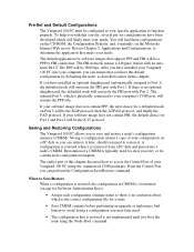
... access the Control Port of a CMEM is typically used for error recovery or for a defaulted node on the Motorola Internet Web server. Restoration of your needs. To help you boot the node using the commercial COM packages. After you can ensure that meets your needs. The internal Port 3, which will be 9600 bps. When to Save/Restore When a configuration is restored, the configuration in this chapter discussed how to FRI connection. Pre-Set and Default Configurations...
... access the Control Port of a CMEM is typically used for error recovery or for a defaulted node on the Motorola Internet Web server. Restoration of your needs. To help you boot the node using the commercial COM packages. After you can ensure that meets your needs. The internal Port 3, which will be 9600 bps. When to Save/Restore When a configuration is restored, the configuration in this chapter discussed how to FRI connection. Pre-Set and Default Configurations...

Operation Guide
Page 54
... provided on the network. The CMEMs will be useful. These descriptions are in the following format: Configuration Diagram • Depicts the equipment and connections in use with your Vanguard 100 PC. Updates to the CMEMs will either completely meet the needs of traffic on CD-ROM as a guideline for the information you believe would benefit other users of this chapter...
... provided on the network. The CMEMs will be useful. These descriptions are in the following format: Configuration Diagram • Depicts the equipment and connections in use with your Vanguard 100 PC. Updates to the CMEMs will either completely meet the needs of traffic on CD-ROM as a guideline for the information you believe would benefit other users of this chapter...

Operation Guide
Page 57
PPP to PPP-3, 999902 is valid for a Switched Virtual Circuit connection between the PPP port and the Frame Relay Service. The Network service will need to call the Node with an address that has the subaddress equal to the PPP port number (i.e., 757503 is auto learned. learn DLCI Annex G Port #2 PPP RFC1490 encapsulation, 57600 bps, VJ compression Port #3 PPP RFC1490 encapsulation, 57600 bps, VJ...
PPP to PPP-3, 999902 is valid for a Switched Virtual Circuit connection between the PPP port and the Frame Relay Service. The Network service will need to call the Node with an address that has the subaddress equal to the PPP port number (i.e., 757503 is auto learned. learn DLCI Annex G Port #2 PPP RFC1490 encapsulation, 57600 bps, VJ compression Port #3 PPP RFC1490 encapsulation, 57600 bps, VJ...

Operation Guide
Page 58
... number is valid for connection to establish the connection. The SLIP connection requires the Network to SLIP-3, 999902 is valid for a Switched Virtual Circuit connection between the SLIP port and the Frame Relay Service. The Frame Relay Port uses the Control Protocol Support ANSI T1.617 Annex D. Optional Application CMEMs V1000004.MEM Standard application as mentioned in Summary V1000004.001 Port #2 PAD, CTP access via CTP switch...
... number is valid for connection to establish the connection. The SLIP connection requires the Network to SLIP-3, 999902 is valid for a Switched Virtual Circuit connection between the SLIP port and the Frame Relay Service. The Frame Relay Port uses the Control Protocol Support ANSI T1.617 Annex D. Optional Application CMEMs V1000004.MEM Standard application as mentioned in Summary V1000004.001 Port #2 PAD, CTP access via CTP switch...

Operation Guide
Page 67
... [3] Security [3] Encapsulation PAD Port Configuration Parameter *Port Type Connection Type Port Control Port Speed Auto Baud Sequence Data Bits per Character Device Parity Number of Stop Bits Profile Name Call Control Terminal Control PAD Prompt Entry Number Remote PAD Parameters Number Autocall Mnemonic Autocall Timeout (sec) Maximum Number of Autocall Attempts NONE PPP Value SLIP SIMP NONE 9600 1 AUTO ON NONE RFC1490 Value PAD SIMP NONE 9600 CR_only 8 NONE 1 DEFAULT NONE...
... [3] Security [3] Encapsulation PAD Port Configuration Parameter *Port Type Connection Type Port Control Port Speed Auto Baud Sequence Data Bits per Character Device Parity Number of Stop Bits Profile Name Call Control Terminal Control PAD Prompt Entry Number Remote PAD Parameters Number Autocall Mnemonic Autocall Timeout (sec) Maximum Number of Autocall Attempts NONE PPP Value SLIP SIMP NONE 9600 1 AUTO ON NONE RFC1490 Value PAD SIMP NONE 9600 CR_only 8 NONE 1 DEFAULT NONE...


