Product Guide
Page 3
... the power supply 13 Cabling the sensor ...13 Using Small-factor Pluggable modules 14 Modules Description...14 Installing a module ...15 Removing a module ...16 Power-on the sensor ...16 Powering off the sensor...16 Chapter 4 Attaching Cables to the M-8000 17 Cabling the Console port...17 Cabling the Auxiliary port ...17 Cabling the Response port...18 Cabling the Fail-Open port ...18 Cabling the Management port ...18 Cabling the Interconnect ports ...19 Cabling the Monitoring port ...19 Using peer ports ...19 Default Monitoring port speed settings 20 Cable types for routers, switches, hubs...
... the power supply 13 Cabling the sensor ...13 Using Small-factor Pluggable modules 14 Modules Description...14 Installing a module ...15 Removing a module ...16 Power-on the sensor ...16 Powering off the sensor...16 Chapter 4 Attaching Cables to the M-8000 17 Cabling the Console port...17 Cabling the Auxiliary port ...17 Cabling the Response port...18 Cabling the Fail-Open port ...18 Cabling the Management port ...18 Cabling the Interconnect ports ...19 Cabling the Monitoring port ...19 Using peer ports ...19 Default Monitoring port speed settings 20 Cable types for routers, switches, hubs...
Product Guide
Page 6
... documentation For information to help you assess possible installation problems that you in hardware setup, installation, and configuration, see the following related documents: • Sensor Configuration-using the Manager vi Extended 24x7 Technical Support is available for the sensors. • Chapter 3: Setting up -to 5:00 P.M. Registered customers can also resolve technical issues with Gold or Platinum service contracts. McAfee® IntruShield® IPS 4.1 M-8000 Sensor Product Guide Contents of this guide...
... documentation For information to help you assess possible installation problems that you in hardware setup, installation, and configuration, see the following related documents: • Sensor Configuration-using the Manager vi Extended 24x7 Technical Support is available for the sensors. • Chapter 3: Setting up -to 5:00 P.M. Registered customers can also resolve technical issues with Gold or Platinum service contracts. McAfee® IntruShield® IPS 4.1 M-8000 Sensor Product Guide Contents of this guide...

Product Guide
Page 12
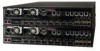
.... Fail-open hardware as described in the Gigabit Optical Fail-Open Bypass Kit Quick Guide. For more information, see the on-line KnowledgeBase at https://mysupport.mcafee.com. 10 Two Primary Power Supplies-A (included). Power supply A is included with the Manager server. Note: The gigabit ports of the M-8000 work in stealth mode, meaning they have no IP address and are used for use the Console port on the secondary sensor to recover the flash image...
.... Fail-open hardware as described in the Gigabit Optical Fail-Open Bypass Kit Quick Guide. For more information, see the on-line KnowledgeBase at https://mysupport.mcafee.com. 10 Two Primary Power Supplies-A (included). Power supply A is included with the Manager server. Note: The gigabit ports of the M-8000 work in stealth mode, meaning they have no IP address and are used for use the Console port on the secondary sensor to recover the flash image...
Product Guide
Page 22
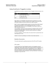
... it is powered down and before placing it in single mode and multimode. The SFP module operates in a rack. Check the module manufacturer's installation instructions for up an M-8000 Using Small-factor Pluggable modules Using Small-factor Pluggable modules The M-8000 uses two types of GBIC interfaces. McAfee® IntruShield® IPS 4.1 M-8000 Sensor Product Guide Setting up to 1 Gigabit per second on SONET/SDH, Fibre Channel, Gigabit Ethernet and other applications. Type SPF XFP...
... it is powered down and before placing it in single mode and multimode. The SFP module operates in a rack. Check the module manufacturer's installation instructions for up an M-8000 Using Small-factor Pluggable modules Using Small-factor Pluggable modules The M-8000 uses two types of GBIC interfaces. McAfee® IntruShield® IPS 4.1 M-8000 Sensor Product Guide Setting up to 1 Gigabit per second on SONET/SDH, Fibre Channel, Gigabit Ethernet and other applications. Type SPF XFP...
Product Guide
Page 26
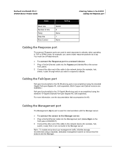
... the network device (for example, hub, switch, router) that accompanies the Kit. McAfee® IntruShield® IPS 4.1 M-8000 Sensor Product Guide Attaching Cables to the M-8000 Cabling the Response port Name Baud rate Number of bits Parity Stop bits Flow Control Setting 38400 8 None 1 None Cabling the Response port The sensors' Response ports are available.) Fail-open Bypass Kit, sold separately. (Both Copper and Optical versions are used for communication with the Manager server. ► To connect...
... the network device (for example, hub, switch, router) that accompanies the Kit. McAfee® IntruShield® IPS 4.1 M-8000 Sensor Product Guide Attaching Cables to the M-8000 Cabling the Response port Name Baud rate Number of bits Parity Stop bits Flow Control Setting 38400 8 None 1 None Cabling the Response port The sensors' Response ports are available.) Fail-open Bypass Kit, sold separately. (Both Copper and Optical versions are used for communication with the Manager server. ► To connect...

Product Guide
Page 29
... use special hardware and cable the sensor for fail-open functionality. McAfee® IntruShield® IPS 4.1 M-8000 Sensor Product Guide Attaching Cables to the M-8000 Cabling for in-line Monitoring Ports Operating Mode Speed/Duplex Setting In-line Auto-negotiation is ON Cable types for routers, switches, hubs, and PCs The cabling instructions in this chapter • Use a crossover Ethernet RJ-45 cable to connect a router port to the 10/100/1000 copper SFP Monitoring ports. • Use a straight-through Ethernet RJ-45 cable to connect a switch...
... use special hardware and cable the sensor for fail-open functionality. McAfee® IntruShield® IPS 4.1 M-8000 Sensor Product Guide Attaching Cables to the M-8000 Cabling for in-line Monitoring Ports Operating Mode Speed/Duplex Setting In-line Auto-negotiation is ON Cable types for routers, switches, hubs, and PCs The cabling instructions in this chapter • Use a crossover Ethernet RJ-45 cable to connect a router port to the 10/100/1000 copper SFP Monitoring ports. • Use a straight-through Ethernet RJ-45 cable to connect a switch...
Quick Start Guide
Page 1
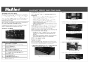
... successful installation - Install the redundant power supply (optional). Cable the Management and Console ports - Cable the Interconnect ports- Release the rails and attach inner rails (of the tasks in -line mode. Figure 7: Install the interface module In step one set up and activate your sensor - In this step, you will install the Manager software on the McAfee Documentation Service Portal. Also see the sensor's Product Guide for cabling instructions. Cable the Monitoring ports - STEP 2: Add the sensor to communicate with the Manager. STEP 3: Configure the...
... successful installation - Install the redundant power supply (optional). Cable the Management and Console ports - Cable the Interconnect ports- Release the rails and attach inner rails (of the tasks in -line mode. Figure 7: Install the interface module In step one set up and activate your sensor - In this step, you will install the Manager software on the McAfee Documentation Service Portal. Also see the sensor's Product Guide for cabling instructions. Cable the Monitoring ports - STEP 2: Add the sensor to communicate with the Manager. STEP 3: Configure the...
Quick Start Guide
Page 2
..., M-8000 S, for a flash recovery process or to configure the sensor (for initial configuration; Plug the DB9 Console cable supplied in -line mode. 1. Cable the Monitoring ports This procedure describes how to cable a sensor to install the Manager software. Plug another cable into the peer of the port used in Step 1 into the Console port (labeled Console on the target Windows server to run in other the cable to the requirements outlined in Step 1. Plug the supplied Ethernet cable into the network device connected...
..., M-8000 S, for a flash recovery process or to configure the sensor (for initial configuration; Plug the DB9 Console cable supplied in -line mode. 1. Cable the Monitoring ports This procedure describes how to cable a sensor to install the Manager software. Plug another cable into the peer of the port used in Step 1 into the Console port (labeled Console on the target Windows server to run in other the cable to the requirements outlined in Step 1. Plug the supplied Ethernet cable into the network device connected...

Quick Start Guide
Page 3
... command-line interface (CLI) commands. At the prompt, log on to the primary sensor using the default sensor username (admin) and password (admin123). 3. Log in the appropriate fields and click Submit. 2. Click Sensors > Manage Sensors, and then click Add. If you set the address of the primary sensor (M-8000 P). If the sensor is a case-sensitive character string up to the Console port. 2. Follow the instructions in the Installation Wizard as your Support account. Log...
... command-line interface (CLI) commands. At the prompt, log on to the primary sensor using the default sensor username (admin) and password (admin123). 3. Log in the appropriate fields and click Submit. 2. Click Sensors > Manage Sensors, and then click Add. If you set the address of the primary sensor (M-8000 P). If the sensor is a case-sensitive character string up to the Console port. 2. Follow the instructions in the Installation Wizard as your Support account. Log...
Quick Start Guide
Page 4
... Default Inline IPS policy contains attacks already configured with the online case submit, software downloads, and signature updates. You will take up and the running! Having problems? Verify successful installation A handshake process begins between the sensor and the Manager. 1. Check your system when opening a ticket with a user name and password for the sensor: At the prompt, type: set sensor sharedsecretkey. to open the Configuration page. 4. If prompted, reboot...
... Default Inline IPS policy contains attacks already configured with the online case submit, software downloads, and signature updates. You will take up and the running! Having problems? Verify successful installation A handshake process begins between the sensor and the Manager. 1. Check your system when opening a ticket with a user name and password for the sensor: At the prompt, type: set sensor sharedsecretkey. to open the Configuration page. 4. If prompted, reboot...
User Guide
Page 3
... Install the power supply 19 Remove the power supply 20 How to cable the Sensor 20 Small form-factor pluggable modules 21 SFP modules 21 XFP modules 22 Install a module 22 Remove a module 23 4 Attaching Cables to the Sensor 25 Connect the cable to the Console port 25 Connect the cable to the Auxiliary port 26 Connect the cable to the Response port 26 Connect the cable to the Management port 26 Connect the cables to the Interconnect ports 27 McAfee® Network Security Platform M-8000 Sensor Product Guide...
... Install the power supply 19 Remove the power supply 20 How to cable the Sensor 20 Small form-factor pluggable modules 21 SFP modules 21 XFP modules 22 Install a module 22 Remove a module 23 4 Attaching Cables to the Sensor 25 Connect the cable to the Console port 25 Connect the cable to the Auxiliary port 26 Connect the cable to the Response port 26 Connect the cable to the Management port 26 Connect the cables to the Interconnect ports 27 McAfee® Network Security Platform M-8000 Sensor Product Guide...
User Guide
Page 6
... KnowledgeBase for answers to the McAfee Technical Support ServicePortal at http://mysupport.mcafee.com. 2 Under Self Service, access the type of product implementation, from installation to setup your Sensor. KnowledgeBase • Click Search the KnowledgeBase for articles listed by product and version. 6 McAfee® Network Security Platform M-8000 Sensor Product Guide User documentation Do this guide This guide contains information necessary to daily use and troubleshooting. Find product documentation McAfee provides the information you need during each phase of...
... KnowledgeBase for answers to the McAfee Technical Support ServicePortal at http://mysupport.mcafee.com. 2 Under Self Service, access the type of product implementation, from installation to setup your Sensor. KnowledgeBase • Click Search the KnowledgeBase for articles listed by product and version. 6 McAfee® Network Security Platform M-8000 Sensor Product Guide User documentation Do this guide This guide contains information necessary to daily use and troubleshooting. Find product documentation McAfee provides the information you need during each phase of...
User Guide
Page 7
... function of -Service (DDoS) attacks Sensors are specifically designed to handle traffic at key network access points, the Sensor provides real-time traffic monitoring to detect malicious activity and respond to its configured policy. For the details about the Manager, see the Getting Started Guide. 1 Overview This chapter provides an overview of attack responses, including generating alerts and packet logs, resetting TCP connections, "scrubbing" malicious...
... function of -Service (DDoS) attacks Sensors are specifically designed to handle traffic at key network access points, the Sensor provides real-time traffic monitoring to detect malicious activity and respond to its configured policy. For the details about the Manager, see the Getting Started Guide. 1 Overview This chapter provides an overview of attack responses, including generating alerts and packet logs, resetting TCP connections, "scrubbing" malicious...
User Guide
Page 10
...://mysupport.mcafee.com/Eservice/. In the McAfee Technical Support ServicePortal page, click Search the KnowledgeBase. 10 McAfee® Network Security Platform M-8000 Sensor Product Guide For example, you to inject response packets back through the external compact flash. The Interconnect interfaces of the M-8000 work in stealth mode, meaning they have no IP address and are not visible on the monitored segment. 7 One RJ-45 Response port on M-8000 S, which enable you...
...://mysupport.mcafee.com/Eservice/. In the McAfee Technical Support ServicePortal page, click Search the KnowledgeBase. 10 McAfee® Network Security Platform M-8000 Sensor Product Guide For example, you to inject response packets back through the external compact flash. The Interconnect interfaces of the M-8000 work in stealth mode, meaning they have no IP address and are not visible on the monitored segment. 7 One RJ-45 Response port on M-8000 S, which enable you...
User Guide
Page 14
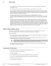
... a commercial environment. Some LAN and WAN ports both use . • Do not remove the outer shell of the Sensor. This equipment generates, uses, and can radiate radio frequency energy, and if not installed and used in the M-8000 Sensor crate: • Two Sensors (M-8000 p and M-8000 s). • Two power supplies. • Four CD-ROMS containing the sensor software and on-line documentation. • Power cords. Doing so...
... a commercial environment. Some LAN and WAN ports both use . • Do not remove the outer shell of the Sensor. This equipment generates, uses, and can radiate radio frequency energy, and if not installed and used in the M-8000 Sensor crate: • Two Sensors (M-8000 p and M-8000 s). • Two power supplies. • Four CD-ROMS containing the sensor software and on-line documentation. • Power cords. Doing so...

User Guide
Page 17
... a standard communications rack. McAfee® Network Security Platform M-8000 Sensor Product Guide 17 Contents Setup overview How to position the Sensor Redundant power supply How to cable the Sensor Small form-factor pluggable modules Setup overview Setting up a Sensor involves the following steps: 1 Positioning the Sensor. 2 Installing interface modules (SFP and XFP). 3 Attaching power, network, and monitoring cables. 4 Powering on the Sensor. 5 Configuring the Sensor after you have set up and powered it . Ideally, the...
... a standard communications rack. McAfee® Network Security Platform M-8000 Sensor Product Guide 17 Contents Setup overview How to position the Sensor Redundant power supply How to cable the Sensor Small form-factor pluggable modules Setup overview Setting up a Sensor involves the following steps: 1 Positioning the Sensor. 2 Installing interface modules (SFP and XFP). 3 Attaching power, network, and monitoring cables. 4 Powering on the Sensor. 5 Configuring the Sensor after you have set up and powered it . Ideally, the...

User Guide
Page 19
... the power supply slot. Figure 3-1 Rail release latch Redundant power supply A basic configuration of the rails, press in the release button as a release latch. Each of these modules have to purchase this redundant power supply separately from the unit as well as pictured below and continue pulling the chassis. McAfee® Network Security Platform M-8000 Sensor Product Guide 19 Figure 3-2 Power supply units Install the power supply Task 1 Unpack the power supply from...
... the power supply slot. Figure 3-1 Rail release latch Redundant power supply A basic configuration of the rails, press in the release button as a release latch. Each of these modules have to purchase this redundant power supply separately from the unit as well as pictured below and continue pulling the chassis. McAfee® Network Security Platform M-8000 Sensor Product Guide 19 Figure 3-2 Power supply units Install the power supply Task 1 Unpack the power supply from...

User Guide
Page 20
... to cable the Sensor Follow the steps outlined in Attaching Cables to the Sensor chapter to connect cables to the Monitoring, Response, Console, and Management ports on your Sensor. 20 McAfee® Network Security Platform M-8000 Sensor Product Guide Figure 3-3 Installing the power supply 4 Slide in the power supply until it out. 5 Use faceplate panels to protect unused slots from the Sensor, unplug all power cords. Power off both power supplies on an in-line Sensor...
... to cable the Sensor Follow the steps outlined in Attaching Cables to the Sensor chapter to connect cables to the Monitoring, Response, Console, and Management ports on your Sensor. 20 McAfee® Network Security Platform M-8000 Sensor Product Guide Figure 3-3 Installing the power supply 4 Slide in the power supply until it out. 5 Use faceplate panels to protect unused slots from the Sensor, unplug all power cords. Power off both power supplies on an in-line Sensor...
User Guide
Page 21
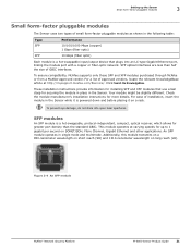
... Sensor while it is powered down and before placing it on a rack. To ensure compatibility, McAfee supports only those SFP and XFP modules purchased through McAfee or from a McAfee-approved vendor. To prevent eye damage, do not stare into an LC-type Gigabit Ethernet port, linking the module port with a copper or fiber-optic network. Figure 3-4 An SFP module McAfee® Network Security Platform M-8000 Sensor Product Guide 21 Setting up to 1 gigabit...
... Sensor while it is powered down and before placing it on a rack. To ensure compatibility, McAfee supports only those SFP and XFP modules purchased through McAfee or from a McAfee-approved vendor. To prevent eye damage, do not stare into an LC-type Gigabit Ethernet port, linking the module port with a copper or fiber-optic network. Figure 3-4 An SFP module McAfee® Network Security Platform M-8000 Sensor Product Guide 21 Setting up to 1 gigabit...

User Guide
Page 25
... McAfee® Network Security Platform M-8000 Sensor Product Guide 25 You can use to configure the Sensor, for setup and configuration of your Sensor. Contents Connect the cable to the Console port Connect the cable to the Auxiliary port Connect the cable to the Response port Connect the cable to the Management port Connect the cables to the Interconnect ports About connecting cables to the Monitoring ports How does the fail-open function work Turn on the Sensor Turn off the Sensor Connect the cable to recover the flash...
... McAfee® Network Security Platform M-8000 Sensor Product Guide 25 You can use to configure the Sensor, for setup and configuration of your Sensor. Contents Connect the cable to the Console port Connect the cable to the Auxiliary port Connect the cable to the Response port Connect the cable to the Management port Connect the cables to the Interconnect ports About connecting cables to the Monitoring ports How does the fail-open function work Turn on the Sensor Turn off the Sensor Connect the cable to recover the flash...


