
Product Guide
Page 3
... Remove a Sensor from the rack 18 Redundant power supply 19 Install the power supply 19 Remove the power supply 20 Cable the Sensor 20 Small form-factor pluggable modules 21 SFP modules 21 XFP modules 22 Install a module 22 Remove a module 23 Power on the Sensor 24 Power off the Sensor 24 4 Attaching Cables to the Sensor 25 Cable the Console port 25 Cable the Auxiliary port 26 Connect the cable to the Response port 26 McAfee® Network Security Platform M-6050 Sensor Product Guide...
... Remove a Sensor from the rack 18 Redundant power supply 19 Install the power supply 19 Remove the power supply 20 Cable the Sensor 20 Small form-factor pluggable modules 21 SFP modules 21 XFP modules 22 Install a module 22 Remove a module 23 Power on the Sensor 24 Power off the Sensor 24 4 Attaching Cables to the Sensor 25 Cable the Console port 25 Cable the Auxiliary port 26 Connect the cable to the Response port 26 McAfee® Network Security Platform M-6050 Sensor Product Guide...

Product Guide
Page 4
... How to use peer ports 27 Default Monitoring port speed settings 28 Cable types for routers, switches, hubs, and PCs 28 Connect the cables for in-line mode 28 Connect the cables for tap mode 29 Connect the cables for SPAN or hub mode 29 Cable the failover interconnection ports 29 How does the fail-open function work 30 5 Troubleshooting the Sensor 31 6 Sensor technical specifications 33 A Regulatory, compliance, and safety information 35 Index 37 4 McAfee® Network Security Platform M-6050 Sensor Product Guide
... How to use peer ports 27 Default Monitoring port speed settings 28 Cable types for routers, switches, hubs, and PCs 28 Connect the cables for in-line mode 28 Connect the cables for tap mode 29 Connect the cables for SPAN or hub mode 29 Cable the failover interconnection ports 29 How does the fail-open function work 30 5 Troubleshooting the Sensor 31 6 Sensor technical specifications 33 A Regulatory, compliance, and safety information 35 Index 37 4 McAfee® Network Security Platform M-6050 Sensor Product Guide

Product Guide
Page 8
... configured policy. High port-density and virtualization provides a highly scalable solution, while Network Security Platform protects against Web and eCommerce mail server exploits. You also need to determine the number of McAfee® ePolicy Orchestrator (McAfee ePO) /McAfee NAC servers required to protect your network to outsourced servers. Sensor can perform many types of attack responses, including generating alerts and packet logs, resetting TCP connections, "scrubbing" malicious packets, and even blocking...
... configured policy. High port-density and virtualization provides a highly scalable solution, while Network Security Platform protects against Web and eCommerce mail server exploits. You also need to determine the number of McAfee® ePolicy Orchestrator (McAfee ePO) /McAfee NAC servers required to protect your network to outsourced servers. Sensor can perform many types of attack responses, including generating alerts and packet logs, resetting TCP connections, "scrubbing" malicious packets, and even blocking...

Product Guide
Page 9
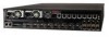
..., it supports four 1 Gigabit full-duplex Ethernet segments or eight 1 Gigabit SPAN ports transmitting aggregated traffic. McAfee® Network Security Platform M-6050 Sensor Product Guide 9 Overview M-6050 key features 1 M-6050 key features The M-6050 Sensor includes the following components: Figure 1-2 M-6050 Sensor Name 1 2 3 4 5 6 7 8 9 10 Description Management port Console port Auxiliary port SFP Gigabit Ethernet Monitoring ports XFP Gigabit Ethernet Monitoring ports Response port Fail-Open Control ports External Compact Flash port Power Supply A Power Supply B 1 One...
..., it supports four 1 Gigabit full-duplex Ethernet segments or eight 1 Gigabit SPAN ports transmitting aggregated traffic. McAfee® Network Security Platform M-6050 Sensor Product Guide 9 Overview M-6050 key features 1 M-6050 key features The M-6050 Sensor includes the following components: Figure 1-2 M-6050 Sensor Name 1 2 3 4 5 6 7 8 9 10 Description Management port Console port Auxiliary port SFP Gigabit Ethernet Monitoring ports XFP Gigabit Ethernet Monitoring ports Response port Fail-Open Control ports External Compact Flash port Power Supply A Power Supply B 1 One...

Product Guide
Page 10
... M-6050 work in stealth mode, meaning they have no IP address and are not visible on the monitored segment. This port is included with each Sensor. Power supply A is used only for flash recovery purposes. This power supply also uses a standard IEC320-C13 port, and you can use it with the Optical Fail-Open Bypass kit. The following table describes the M-6050 front panel LEDs. These Monitoring interfaces of the M-6050 work in -line...
... M-6050 work in stealth mode, meaning they have no IP address and are not visible on the monitored segment. This port is included with each Sensor. Power supply A is used only for flash recovery purposes. This power supply also uses a standard IEC320-C13 port, and you can use it with the Optical Fail-Open Bypass kit. The following table describes the M-6050 front panel LEDs. These Monitoring interfaces of the M-6050 work in -line...

Product Guide
Page 14
...; One Sensor. • One power supply. • Two CD-ROMs containing the Sensor software and on regulatory, compliance, and other equipment and direct the flow of cooling air through the chassis. • To avoid electric shock, do not stare into the aperture of rack mounting rails. 14 McAfee® Network Security Platform M-6050 Sensor Product Guide Note the following accessories are...
...; One Sensor. • One power supply. • Two CD-ROMs containing the Sensor software and on regulatory, compliance, and other equipment and direct the flow of cooling air through the chassis. • To avoid electric shock, do not stare into the aperture of rack mounting rails. 14 McAfee® Network Security Platform M-6050 Sensor Product Guide Note the following accessories are...

Product Guide
Page 17
... of this guide. Remove the power cable and all network interface cables from the Sensor. Ideally, the Sensor should be monitoring. McAfee® Network Security Platform M-6050 Sensor Product Guide 17 To mount the Sensor on the chassis, make sure that the power is off the Sensor Setup overview Setting up a Sensor involves the following steps: 1 Positioning the Sensor. 2 Installing interface modules (SFP and XFP). 3 Attaching power, network, and monitoring cables. 4 Powering on the Sensor. 5 Configuring the Sensor...
... of this guide. Remove the power cable and all network interface cables from the Sensor. Ideally, the Sensor should be monitoring. McAfee® Network Security Platform M-6050 Sensor Product Guide 17 To mount the Sensor on the chassis, make sure that the power is off the Sensor Setup overview Setting up a Sensor involves the following steps: 1 Positioning the Sensor. 2 Installing interface modules (SFP and XFP). 3 Attaching power, network, and monitoring cables. 4 Powering on the Sensor. 5 Configuring the Sensor...

Product Guide
Page 20
... 3-3 Installing the power supply 4 Slide in Attaching Cables to the Sensor to connect cables to the monitoring, response, console, and management ports on your Sensor. 20 McAfee® Network Security Platform M-6050 Sensor Product Guide Remove the power supply Note that you are hot-swappable. Cable the Sensor Follow the steps outlined in the power supply until it out. 6 Use faceplate panels to mate the connectors solidly with the optional redundant power supply, McAfee recommends that the power supplies...
... 3-3 Installing the power supply 4 Slide in Attaching Cables to the Sensor to connect cables to the monitoring, response, console, and management ports on your Sensor. 20 McAfee® Network Security Platform M-6050 Sensor Product Guide Remove the power supply Note that you are hot-swappable. Cable the Sensor Follow the steps outlined in the power supply until it out. 6 Use faceplate panels to mate the connectors solidly with the optional redundant power supply, McAfee recommends that the power supplies...
Product Guide
Page 21
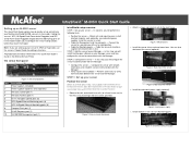
...). Setting up to 1 gigabit per second on SONET/SDH, Fibre Channel, Gigabit Ethernet and other applications. Click Search the KnowledgeBase. SFP modules An SFP module is a hot-swappable, protocol-independant, compact, optical receiver, which allows for more details. SFP optical interfaces are less than the standard GBIC. Figure 3-4 An SFP module McAfee® Network Security Platform M-6050 Sensor Product Guide 21 Check the module manufacturer's installation instructions for greater port...
...). Setting up to 1 gigabit per second on SONET/SDH, Fibre Channel, Gigabit Ethernet and other applications. Click Search the KnowledgeBase. SFP modules An SFP module is a hot-swappable, protocol-independant, compact, optical receiver, which allows for more details. SFP optical interfaces are less than the standard GBIC. Figure 3-4 An SFP module McAfee® Network Security Platform M-6050 Sensor Product Guide 21 Check the module manufacturer's installation instructions for greater port...

Product Guide
Page 25
... fail-open function work Cable the Console port The Console port is labeled Console on the Sensor. McAfee® Network Security Platform M-6050 Sensor Product Guide 25 This port is used to set up and configure the Sensor. Task 1 For console connections, plug the DB9 Console cable supplied by McAfee into the Console port. 4 Attaching Cables to the Sensor Follow the steps outlined in -line mode Connect the cables for tap mode Connect the cables for SPAN or hub mode Cable the failover interconnection ports How does the fail-open port Cable the Management port About connecting cables...
... fail-open function work Cable the Console port The Console port is labeled Console on the Sensor. McAfee® Network Security Platform M-6050 Sensor Product Guide 25 This port is used to set up and configure the Sensor. Task 1 For console connections, plug the DB9 Console cable supplied by McAfee into the Console port. 4 Attaching Cables to the Sensor Follow the steps outlined in -line mode Connect the cables for tap mode Connect the cables for SPAN or hub mode Cable the failover interconnection ports How does the fail-open port Cable the Management port About connecting cables...

Product Guide
Page 26
... panel. 2 Connect a modem to the Aux port. 3 Connect a telephone line to the Sensor for the 10 Gigabit Monitoring ports is accomplished using the standard Gigabit Fail-open Bypass Kit, which is sold separately. Task 1 Plug a Cat-5e Ethernet cable into the Auxiliary port. For more information, see the documentation that accompanies the Kit. Required settings for communication with the Manager server. 26 McAfee® Network Security Platform M-6050 Sensor Product Guide This port is...
... panel. 2 Connect a modem to the Aux port. 3 Connect a telephone line to the Sensor for the 10 Gigabit Monitoring ports is accomplished using the standard Gigabit Fail-open Bypass Kit, which is sold separately. Task 1 Plug a Cat-5e Ethernet cable into the Auxiliary port. For more information, see the documentation that accompanies the Kit. Required settings for communication with the Manager server. 26 McAfee® Network Security Platform M-6050 Sensor Product Guide This port is...

Product Guide
Page 28
... router. 4 Attaching Cables to the Sensor Connect the cables for in-line mode Default Monitoring port speed settings Make sure that you want to monitor. Cable types for routers, switches, hubs, and PCs This section lists the types of cables that you must use peer ports on the Sensor Monitoring ports to which they stop the flow of this chapter. See also Cable types for in Step 1. 3 Connect the other network devices: • Use a crossover Ethernet RJ-45 cable to connect a router port...
... router. 4 Attaching Cables to the Sensor Connect the cables for in-line mode Default Monitoring port speed settings Make sure that you want to monitor. Cable types for routers, switches, hubs, and PCs This section lists the types of cables that you must use peer ports on the Sensor Monitoring ports to which they stop the flow of this chapter. See also Cable types for in Step 1. 3 Connect the other network devices: • Use a crossover Ethernet RJ-45 cable to connect a router port...

Product Guide
Page 37
... 5 F front panel 10, 14, 15 H hot swappable power supply 20 K key features 9 M Management port 26 McAfee ServicePortal, accessing 6 module 22, 23 P peer 27, 29 Pluggable 21 ports 9 power supply 19 R rack 14, 17, 18 Response port 26 S Safety 35 sensor responsibilities 7 ServicePortal, finding product documentation 6 setting up 17, 25 SFP 21 SFP module 24 specifications 33 T Technical Support, finding product information 6 Troubleshooting 7, 8, 13, 17, 31 X XFP module 22 McAfee® Network Security Platform M-6050 Sensor Product Guide 37
... 5 F front panel 10, 14, 15 H hot swappable power supply 20 K key features 9 M Management port 26 McAfee ServicePortal, accessing 6 module 22, 23 P peer 27, 29 Pluggable 21 ports 9 power supply 19 R rack 14, 17, 18 Response port 26 S Safety 35 sensor responsibilities 7 ServicePortal, finding product documentation 6 setting up 17, 25 SFP 21 SFP module 24 specifications 33 T Technical Support, finding product information 6 Troubleshooting 7, 8, 13, 17, 31 X XFP module 22 McAfee® Network Security Platform M-6050 Sensor Product Guide 37

Product Manual
Page 3
... 12 Installing the power supply 12 Removing the power supply 13 Cabling the sensor ...13 Using Small Form-factor Pluggable modules 13 Modules Description...14 Installing a module ...15 Removing a module ...15 Power-on the sensor ...15 Powering off the sensor...16 Attaching Cables to the M-6050 17 Cabling the Console port...17 Cabling the Auxiliary port ...17 Cabling the Response port...18 Cabling the Fail-Open port ...18 Cabling the Management port ...18 Cabling the Monitoring port ...19 Using peer ports ...19 efault Monitoring port speed settings 20 Cable types for routers, switches...
... 12 Installing the power supply 12 Removing the power supply 13 Cabling the sensor ...13 Using Small Form-factor Pluggable modules 13 Modules Description...14 Installing a module ...15 Removing a module ...15 Power-on the sensor ...15 Powering off the sensor...16 Attaching Cables to the M-6050 17 Cabling the Console port...17 Cabling the Auxiliary port ...17 Cabling the Response port...18 Cabling the Fail-Open port ...18 Cabling the Management port ...18 Cabling the Monitoring port ...19 Using peer ports ...19 efault Monitoring port speed settings 20 Cable types for routers, switches...
Product Manual
Page 6
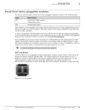
... preliminary steps you must follow prior to configuring the sensor. • Chapter 4: Attaching Cables to the M-6050 Sensor describes how to attach network, monitoring, configuration, and response cables to the sensor, and how to cable the sensor to operate in hardware setup, installation, and configuration, see the following related documents: • Sensor Configuration-using the Manager • Sensor Configuration Guide-using CLI • Sensor Configuration Guide-using the Wizard For information to -date documentation, technical...
... preliminary steps you must follow prior to configuring the sensor. • Chapter 4: Attaching Cables to the M-6050 Sensor describes how to attach network, monitoring, configuration, and response cables to the sensor, and how to cable the sensor to operate in hardware setup, installation, and configuration, see the following related documents: • Sensor Configuration-using the Manager • Sensor Configuration Guide-using CLI • Sensor Configuration Guide-using the Wizard For information to -date documentation, technical...

Product Manual
Page 26
... used for communication with the Manager server. ► To connect the sensor to the Manager server: 1 Plug a Cat-5e Ethernet cable into the Response port (labeled Rx on the sensor front panel). 18 when operating in TAP or SPAN mode, for example, you want to respond to attacks. McAfee® IntruShield® IPS 4.1 M-6050 Sensor Product Guide Name Baud rate Number of the cable to the network device (for example, hub, switch, router...
... used for communication with the Manager server. ► To connect the sensor to the Manager server: 1 Plug a Cat-5e Ethernet cable into the Response port (labeled Rx on the sensor front panel). 18 when operating in TAP or SPAN mode, for example, you want to respond to attacks. McAfee® IntruShield® IPS 4.1 M-6050 Sensor Product Guide Name Baud rate Number of the cable to the network device (for example, hub, switch, router...
Quick Start Guide
Page 1
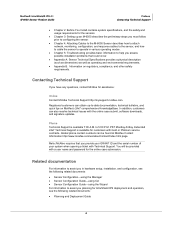
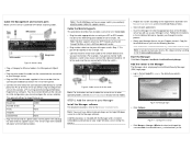
... Description Power supply A (included) Power supply B (optional; install the sensor in the sensor's Monitoring ports. Install the redundant power supply (optional). Install modules in a rack. Cable the sensor to monitor a segment of a three-in -line mode enables you will use for in -one , you will install the Manager software on the McAfee Service Portal. In this step, you are available in the IntruShield Sensor Configuration Guides and in -line. Connect the sensor to a console you will configure the...
... Description Power supply A (included) Power supply B (optional; install the sensor in the sensor's Monitoring ports. Install the redundant power supply (optional). Install modules in a rack. Cable the sensor to monitor a segment of a three-in -line mode enables you will use for in -one , you will install the Manager software on the McAfee Service Portal. In this step, you are available in the IntruShield Sensor Configuration Guides and in -line. Connect the sensor to a console you will configure the...
Quick Start Guide
Page 2
... network device connected to install the Manager software. Default Login ID is powered OFF before attaching cables. Figure 8: Sensor setup 1. Note: McAfee supports only those SFP modules purchased through the entire process. 4. Insert the Manager CD into the appropriate drive of the cable into the Console port (labeled Console on the target Windows server to your Manager server. 3. Start the Manager Click Start > Programs > IntruShield > IntruShield Security Manager. This port will be using to the switch.) Figure 9: Cable sensor for in -line mode...
... network device connected to install the Manager software. Default Login ID is powered OFF before attaching cables. Figure 8: Sensor setup 1. Note: McAfee supports only those SFP modules purchased through the entire process. 4. Insert the Manager CD into the appropriate drive of the cable into the Console port (labeled Console on the target Windows server to your Manager server. 3. Start the Manager Click Start > Programs > IntruShield > IntruShield Security Manager. This port will be using to the switch.) Figure 9: Cable sensor for in -line mode...

Quick Start Guide
Page 3
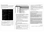
... the Manager server: At the prompt, type: set manager ip Example: set in items 4 through 7 and item 10. Log on 3. Figure 14: Sensor CLI log on to enter the new password and prompts you set manager ip 192.168.2.8 7. Change the sensor password: At the prompt, type: passwd The sensor prompts you to the sensor using the default sensor username (admin) and password (admin123). Note: A password must manually enter the complete command syntax as the Manager, set the address...
... the Manager server: At the prompt, type: set manager ip Example: set in items 4 through 7 and item 10. Log on 3. Figure 14: Sensor CLI log on to enter the new password and prompts you set manager ip 192.168.2.8 7. Change the sensor password: At the prompt, type: passwd The sensor prompts you to the sensor using the default sensor username (admin) and password (admin123). Note: A password must manually enter the complete command syntax as the Manager, set the address...
Quick Start Guide
Page 4
... port settings match the cabling (for alert statistics as described in STEP 1, Cable the Monitoring ports (on both devices to see the Intrushield Sensor Configuration Guide-using ISM, or click the Detailed Help buttons in the upper-right corner of each window in the System Health section. Phone Technical Support is triggered, the sensor automatically blocks the attack. In the sensor CLI, type: status. Manager status should be up, and sensor status...
... port settings match the cabling (for alert statistics as described in STEP 1, Cable the Monitoring ports (on both devices to see the Intrushield Sensor Configuration Guide-using ISM, or click the Detailed Help buttons in the upper-right corner of each window in the System Health section. Phone Technical Support is triggered, the sensor automatically blocks the attack. In the sensor CLI, type: status. Manager status should be up, and sensor status...


