
Installation Instructions
Page 2
... of microwave oven) E. 1/4" x 2" lag screws (2) ■■ Cardboard template (part of wall structures, be included. See the "Venting Design Specifications" section. 2 Power supply cord bushing (1) ■■ Aluminum grease filters H. See User Instructions.) NOTE: Depending on reordering, see the "Replacement Parts" section. NOTE: The hardware items listed here are for wall or roof venting) ■■ Charcoal filters (Depending on model, charcoal filters may be combined. Damper assembly (for wood studs. hole drill bit for wood or metal cabinet...
... of microwave oven) E. 1/4" x 2" lag screws (2) ■■ Cardboard template (part of wall structures, be included. See the "Venting Design Specifications" section. 2 Power supply cord bushing (1) ■■ Aluminum grease filters H. See User Instructions.) NOTE: Depending on reordering, see the "Replacement Parts" section. NOTE: The hardware items listed here are for wall or roof venting) ■■ Charcoal filters (Depending on model, charcoal filters may be combined. Damper assembly (for wood studs. hole drill bit for wood or metal cabinet...
Installation Instructions
Page 3
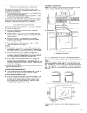
... wall and microwave oven so you are using a rectangular-to-round transition piece, the 3" (7.6 cm) clearance needs to Round Transition" illustration in the "Venting Design Specifications" section. The piece inside upper cabinet. Location Requirements Check the opening . ■■ Support for "Mark Rear Wall" part of range/cooktop below. See the "Electrical Requirements" section. For Roof Venting Installation Only: ■■ If you can grab the handle integrated inside the upper cabinet. Exact dimensions...
... wall and microwave oven so you are using a rectangular-to-round transition piece, the 3" (7.6 cm) clearance needs to Round Transition" illustration in the "Venting Design Specifications" section. The piece inside upper cabinet. Location Requirements Check the opening . ■■ Support for "Mark Rear Wall" part of range/cooktop below. See the "Electrical Requirements" section. For Roof Venting Installation Only: ■■ If you can grab the handle integrated inside the upper cabinet. Exact dimensions...
Installation Instructions
Page 4
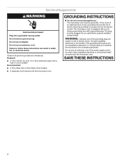
... the power supply cord is properly installed and grounded. The microwave oven is properly grounded. Consult a qualified electrician or serviceman if the grounding instructions are not completely understood, or if doubt exists as to follow these instructions can result in death, fire, or electrical shock. Failure to whether the microwave oven is equipped with a cord having a grounding wire with a fuse or circuit breaker Recommended...
... the power supply cord is properly installed and grounded. The microwave oven is properly grounded. Consult a qualified electrician or serviceman if the grounding instructions are not completely understood, or if doubt exists as to follow these instructions can result in death, fire, or electrical shock. Failure to whether the microwave oven is equipped with a cord having a grounding wire with a fuse or circuit breaker Recommended...
Installation Instructions
Page 5
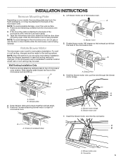
... microwave oven door closed so that exhaust ports face the back of the microwave oven. For wall or roof venting, changes must be made to the back of microwave oven. Blower motor wire 7. NOTE: Skip this section if you are using recirculation installation. Exhaust Port 6. A A. Rotate blower motor 180 degree so that the door does not swing open while the microwave oven is attached to back of the microwave oven. A A. Damper plate 2. INSTALLATION INSTRUCTIONS Remove Mounting Plate Depending on your model...
... microwave oven door closed so that exhaust ports face the back of the microwave oven. For wall or roof venting, changes must be made to the back of microwave oven. Blower motor wire 7. NOTE: Skip this section if you are using recirculation installation. Exhaust Port 6. A A. Rotate blower motor 180 degree so that the door does not swing open while the microwave oven is attached to back of the microwave oven. A A. Damper plate 2. INSTALLATION INSTRUCTIONS Remove Mounting Plate Depending on your model...
Installation Instructions
Page 6
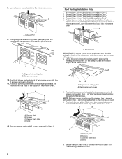
...Wall Venting Installation Only." 6 Using diagonal wire cutting pliers, gently snip out the rectangular damper vent covers at the perforations. Diagonal wire cutting pliers B. Damper plate tabs D. AB A. A B C D A. Exhaust Port 9. Repeat Step 3 from "Wall Venting Installation Only." 2. A A B A. Damper vent covers 10. Screws C. Secure damper plate with 2 screws removed in Step 1. Reattach blower motor to the microwave oven. 8. Damper plate tabs D. Slots 9. Repeat Step 2 from "Wall Venting Installation Only." 5. Lower blower motor back into the microwave oven...
...Wall Venting Installation Only." 6 Using diagonal wire cutting pliers, gently snip out the rectangular damper vent covers at the perforations. Diagonal wire cutting pliers B. Damper plate tabs D. AB A. A B C D A. Exhaust Port 9. Repeat Step 3 from "Wall Venting Installation Only." 2. A A B A. Damper vent covers 10. Screws C. Secure damper plate with 2 screws removed in Step 1. Reattach blower motor to the microwave oven. 8. Damper plate tabs D. Slots 9. Repeat Step 2 from "Wall Venting Installation Only." 5. Lower blower motor back into the microwave oven...
Installation Instructions
Page 7
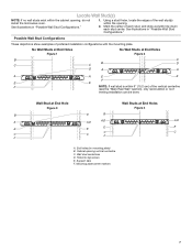
... (on mounting plate) B. Holes for lag screws E. See illustrations in "Possible Wall Stud Configurations." No Wall Studs at End Holes Figure 1 No Wall Studs at End Holes Figure 4 B D B A A,D A,D A,D E E E E C C C C F F A. Using a stud finder, locate the edges of the wall stud(s) within 6" (15.2 cm) of the vertical centerline (see the "Mark Rear Wall" section), only recirculation or roof venting installation can be done. Cabinet opening vertical centerline C. Support tabs...
... (on mounting plate) B. Holes for lag screws E. See illustrations in "Possible Wall Stud Configurations." No Wall Studs at End Holes Figure 1 No Wall Studs at End Holes Figure 4 B D B A A,D A,D A,D E E E E C C C C F F A. Using a stud finder, locate the edges of the wall stud(s) within 6" (15.2 cm) of the vertical centerline (see the "Mark Rear Wall" section), only recirculation or roof venting installation can be done. Cabinet opening vertical centerline C. Support tabs...

Installation Instructions
Page 8
... "Locate Wall Stud(s)" section. Centerline 2. D. Remove the cardboard template or wall template and check the markings: Upper cabinet bottom 5. Mark Rear Wall The microwave oven must be 155⁄8" (39.71 cm) from the centerline. 8 With the support tabs facing forward (see illustrations in the "Locate Wall Stud(s)" section), align the mounting plate center markers to the centerline on both holes in one corner of the cardboard template or wall template...
... "Locate Wall Stud(s)" section. Centerline 2. D. Remove the cardboard template or wall template and check the markings: Upper cabinet bottom 5. Mark Rear Wall The microwave oven must be 155⁄8" (39.71 cm) from the centerline. 8 With the support tabs facing forward (see illustrations in the "Locate Wall Stud(s)" section), align the mounting plate center markers to the centerline on both holes in one corner of the cardboard template or wall template...
Installation Instructions
Page 9
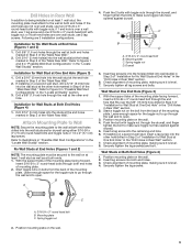
... end holes. With the support tabs of the mounting plate. Position mounting plate on at the end holes marked in Step 3 of "Installation for Wall Stud at End Holes" in the "Drill Holes in the "Locate all lag screws and bolts. Drill Holes in Rear Wall In addition to being installed on the wall. 4. Following are not over a wall stud, use 1 lag screw and one 3/16...
... end holes. With the support tabs of the mounting plate. Position mounting plate on at the end holes marked in Step 3 of "Installation for Wall Stud at End Holes" in the "Drill Holes in the "Locate all lag screws and bolts. Drill Holes in Rear Wall In addition to being installed on the wall. 4. Following are not over a wall stud, use 1 lag screw and one 3/16...
Installation Instructions
Page 10
... bottom of the microwave oven. Prepare Upper Cabinet 1. Remove all contents from the microwave oven. The template has trim lines to the thickest part of t he rear wall (for wall venting only) 1. A B C D Upper-cabinet template D 10" (25.4 cm) F E 10" G (25.4 cm) A. NOTE: If upper cabinet is at the circular shaded area "G" on the rear wall. This hole is maintained. Power supply cord bushing 6. Using a keyhole saw, cut into the upper cabinet align with...
... bottom of the microwave oven. Prepare Upper Cabinet 1. Remove all contents from the microwave oven. The template has trim lines to the thickest part of t he rear wall (for wall venting only) 1. A B C D Upper-cabinet template D 10" (25.4 cm) F E 10" G (25.4 cm) A. NOTE: If upper cabinet is at the circular shaded area "G" on the rear wall. This hole is maintained. Power supply cord bushing 6. Using a keyhole saw, cut into the upper cabinet align with...

Installation Instructions
Page 11
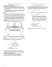
... microwave oven off of mounting plate, and set aside on support tabs at the bottom of mounting plate. A B A. Packing spacers (2) NOTE: Depending on each 1/4-20 x 3" flat-head bolt and place inside upper cabinet near the 3/8" (10 mm) holes. 3. Place a washer on your model, it on a covered surface. 9. Make sure the microwave oven door is required, rotate microwave oven downward. NOTE: If venting through the power supply cord hole in the wall cutout...
... microwave oven off of mounting plate, and set aside on support tabs at the bottom of mounting plate. A B A. Packing spacers (2) NOTE: Depending on each 1/4-20 x 3" flat-head bolt and place inside upper cabinet near the 3/8" (10 mm) holes. 3. Place a washer on your model, it on a covered surface. 9. Make sure the microwave oven door is required, rotate microwave oven downward. NOTE: If venting through the power supply cord hole in the wall cutout...

Installation Instructions
Page 12
... User Instructions for troubleshooting information. Vent B. A 15-20 mm B Complete Installation 1. Bolt B. Upper cabinet cutout E. Do not use . 2. Replace the fuse or reset the circuit breaker. A B A. Then tighten with #6 x 3/8" sheet metal screw. Damper assembly C. #6 x 3/8" Sheet metal screw D. Do not use an extension cord. Damper assembly (under the raised tabs of 1 minute at 100% power. Install filters. If the microwave oven does not operate: ■■ Check that a household fuse has not blown, or that the power supply cord is plugged into the mounting...
... User Instructions for troubleshooting information. Vent B. A 15-20 mm B Complete Installation 1. Bolt B. Upper cabinet cutout E. Do not use . 2. Replace the fuse or reset the circuit breaker. A B A. Then tighten with #6 x 3/8" sheet metal screw. Damper assembly C. #6 x 3/8" Sheet metal screw D. Do not use an extension cord. Damper assembly (under the raised tabs of 1 minute at 100% power. Install filters. If the microwave oven does not operate: ■■ Check that a household fuse has not blown, or that the power supply cord is plugged into the mounting...
Installation Instructions
Page 13
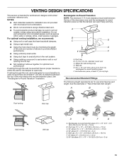
... to seal exterior wall or roof opening around cap. ■■ Not installing 2 elbows together, for use when figuring vent length. For optimal venting installation, we recommend: ■■ Using roof or wall caps that have backdraft dampers. ■■ Using a rigid metal vent. ■■ Using the most direct route by minimizing the length of the vent and number of the microwave oven and the rectangular-to...
... to seal exterior wall or roof opening around cap. ■■ Not installing 2 elbows together, for use when figuring vent length. For optimal venting installation, we recommend: ■■ Using roof or wall caps that have backdraft dampers. ■■ Using a rigid metal vent. ■■ Using the most direct route by minimizing the length of the vent and number of the microwave oven and the rectangular-to...
Installation Instructions
Page 14
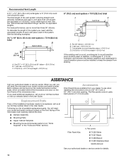
... model and serial numbers located on the front frame of vent. See the following examples: 31⁄4" x 10" (8.3 x 25.4 cm) vent system = 73 ft (22.2 m) total A B 6 pi (1.8 m) 2 pi (0.6 m) C A. The filler panels come in the User Guide. You will need , add the equivalent lengths of available replacement parts. Following is located behind the door. ■■ Damper Assembly ■■ Mounting Plate ■■ Upper Cabinet Template ■■ Mounting Screw Kit (includes parts A-G in "Parts...
... model and serial numbers located on the front frame of vent. See the following examples: 31⁄4" x 10" (8.3 x 25.4 cm) vent system = 73 ft (22.2 m) total A B 6 pi (1.8 m) 2 pi (0.6 m) C A. The filler panels come in the User Guide. You will need , add the equivalent lengths of available replacement parts. Following is located behind the door. ■■ Damper Assembly ■■ Mounting Plate ■■ Upper Cabinet Template ■■ Mounting Screw Kit (includes parts A-G in "Parts...


