Installation Guide
Page 1
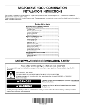
...) wide. These installation instructions cover different models. Table of Contents MICROWAVE HOOD COMBINATION SAFETY 1 INSTALLATION REQUIREMENTS 2 Tools and Parts 2 Remove Cardboard Template 2 Location Requirements 2 Product Dimensions 3 Electrical Requirements 3 INSTALLATION INSTRUCTIONS 4 Remove Mounting Plate 4 Rotate Blower Motor 4 Locate Wall Stud(s 6 Mark Rear Wall 7 Drill Holes in Rear Wall 7 Attach Mounting Plate to...
...) wide. These installation instructions cover different models. Table of Contents MICROWAVE HOOD COMBINATION SAFETY 1 INSTALLATION REQUIREMENTS 2 Tools and Parts 2 Remove Cardboard Template 2 Location Requirements 2 Product Dimensions 3 Electrical Requirements 3 INSTALLATION INSTRUCTIONS 4 Remove Mounting Plate 4 Rotate Blower Motor 4 Locate Wall Stud(s 6 Mark Rear Wall 7 Drill Holes in Rear Wall 7 Attach Mounting Plate to...
Installation Guide
Page 2
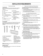
... piece, the 3" (7.6 cm) clearance needs to use as a rear wall template. 1. The piece inside upper cabinet. See "Installation Dimensions" illustration. ■ Minimum one 2" x 4" (50.8 x 101.6 mm) wood wall stud and minimum 3/8" (10 mm) thickness...other damages. Sheet metal screws (2) G. Power supply cord bushing (1) H. Special Requirements For Wall Venting Installation Only: ■ Cutout must provide: ■ Minimum installation dimensions. A B C D E FG H A 1/4-20 x 3" round-head bolts (2) B. 1/4-20 x 3" flat-head bolts (2) C. The location must be combined....
... piece, the 3" (7.6 cm) clearance needs to use as a rear wall template. 1. The piece inside upper cabinet. See "Installation Dimensions" illustration. ■ Minimum one 2" x 4" (50.8 x 101.6 mm) wood wall stud and minimum 3/8" (10 mm) thickness...other damages. Sheet metal screws (2) G. Power supply cord bushing (1) H. Special Requirements For Wall Venting Installation Only: ■ Cutout must provide: ■ Minimum installation dimensions. A B C D E FG H A 1/4-20 x 3" round-head bolts (2) B. 1/4-20 x 3" flat-head bolts (2) C. The location must be combined....

Installation Guide
Page 3
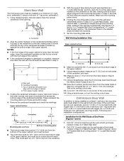
Exact dimensions may vary depending on type of electric shock by providing an escape wire for 66" (167.6 cm) installation height. Do not remove ground prong. Do ... in death, fire, or electrical shock. Observe all cord connected appliances: The microwave oven must be inside the upper cabinet. Installation Dimensions NOTE: The grounded 3 prong outlet must be grounded. Product Dimensions 17¹⁄₈" (43.5 cm) 16¹⁄₄" (41.3 cm) (1(+.40/1-1c.³06m⁄₈¹c")⁄...
Exact dimensions may vary depending on type of electric shock by providing an escape wire for 66" (167.6 cm) installation height. Do not remove ground prong. Do ... in death, fire, or electrical shock. Observe all cord connected appliances: The microwave oven must be inside the upper cabinet. Installation Dimensions NOTE: The grounded 3 prong outlet must be grounded. Product Dimensions 17¹⁄₈" (43.5 cm) 16¹⁄₄" (41.3 cm) (1(+.40/1-1c.³06m⁄₈¹c")⁄...
Installation Guide
Page 7
... 8, and mark. 11. These represent the mounting plate's end holes and bottom edge. 4. Cut a 3/4" (19 mm) hole in one 1/4-20 x 3" round-head bolt with the dimensions described in Step 4. Measure down from the mark made in Step 9 to complete the 12" x 4" (30.5 x 10.2 cm) rectangle. Remove the cardboard template and check...
... 8, and mark. 11. These represent the mounting plate's end holes and bottom edge. 4. Cut a 3/4" (19 mm) hole in one 1/4-20 x 3" round-head bolt with the dimensions described in Step 4. Measure down from the mark made in Step 9 to complete the 12" x 4" (30.5 x 10.2 cm) rectangle. Remove the cardboard template and check...

Installation Guide
Page 8
... outlet. 2. Installation for Wall Studs at Both End Holes (Figure 4) 1. Drill 3/16" (5 mm) holes into the remaining end hole. 6. Make sure the 10" (25.4 cm) dimension from upper cabinet. 3.
... outlet. 2. Installation for Wall Studs at Both End Holes (Figure 4) 1. Drill 3/16" (5 mm) holes into the remaining end hole. 6. Make sure the 10" (25.4 cm) dimension from upper cabinet. 3.
