
Service Manual
Page 1
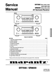
... INPUT A/D S-DIRECT MULTI SLEEP DISPLAY OFF MUTE TV LD DVD VCR1 DSS/VCR2 AUX CDR/MD TAPE CD TUNER S-VIDEO AUX INPUT VIDEO L AUDIO R SR8000 AV SURROUND RECEIVER SR8000 SURROUND CLEAR MEMORY TUNING/PRESET DIGITAL DOLBY DIGITAL SURROUND VOLUME L C R LFE LS S RS PEAK DOWN UP F/P MODE STANDBY POWER ON/STANDBY PHONES 6ch... ...56 9. BLOCK DIAGRAM ...5 4. ELECTRICAL ADJUSTMENTS ...58 10. ELECTRICAL PARTS LIST ...65 Please use this service manual with referring to the user guide ( D.F.U. ) without fail. TECHNICAL SPECIFICATIONS ...1 2.
... INPUT A/D S-DIRECT MULTI SLEEP DISPLAY OFF MUTE TV LD DVD VCR1 DSS/VCR2 AUX CDR/MD TAPE CD TUNER S-VIDEO AUX INPUT VIDEO L AUDIO R SR8000 AV SURROUND RECEIVER SR8000 SURROUND CLEAR MEMORY TUNING/PRESET DIGITAL DOLBY DIGITAL SURROUND VOLUME L C R LFE LS S RS PEAK DOWN UP F/P MODE STANDBY POWER ON/STANDBY PHONES 6ch... ...56 9. BLOCK DIAGRAM ...5 4. ELECTRICAL ADJUSTMENTS ...58 10. ELECTRICAL PARTS LIST ...65 Please use this service manual with referring to the user guide ( D.F.U. ) without fail. TECHNICAL SPECIFICATIONS ...1 2.
Service Manual
Page 2
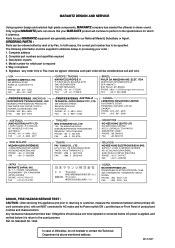
... 8.1, LEVEL 8, MENARA GENESIS, NO. 33, JALAN SULTAN ISMAIL, 50250 KUALA LUMPUR, MALAYSIA PHONE : +60 3 - 2457677 FAX : +60 3 - 2458180 JAPAN Technical MARANTZ JAPAN, INC. 35- 1, 7- UL Standard No. 1492. Complete part numbers and quantities required 3. P.O.BOX 80002, BUILDING SFF2 5600 JB EINDHOVEN THE NETHERLANDS PHONE : +31... Ref. In case of shipment 6. The following information must be signed, otherwise such part order will continue to perform to the specifications for your order : 1. Description of product and controls and chassis bottom. BOX 350 MT. YUING CO., LTD. 6 TH FL...
... 8.1, LEVEL 8, MENARA GENESIS, NO. 33, JALAN SULTAN ISMAIL, 50250 KUALA LUMPUR, MALAYSIA PHONE : +60 3 - 2457677 FAX : +60 3 - 2458180 JAPAN Technical MARANTZ JAPAN, INC. 35- 1, 7- UL Standard No. 1492. Complete part numbers and quantities required 3. P.O.BOX 80002, BUILDING SFF2 5600 JB EINDHOVEN THE NETHERLANDS PHONE : +31... Ref. In case of shipment 6. The following information must be signed, otherwise such part order will continue to perform to the specifications for your order : 1. Description of product and controls and chassis bottom. BOX 350 MT. YUING CO., LTD. 6 TH FL...
Service Manual
Page 3
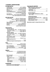
...L/R, CENTER, SURROUND L/R ( 1 KHz 0.01% or less SUBWOOFER ( 40 Hz 0.07% or less Signal to Noise Ratio ( IHF-A 96 dB Channel Separation ( 1 KHz 70 dB Specifications subject to 8 MHz ( - 1 dB) S/N 60 dB GENERAL Power Requirement AC 120V 60 Hz (U version) AC 220 50/60 Hz (K version) AC 230V 50 Hz (N, S ... FRONT (20 Hz - 20 kHz) ..... 8 ohms 100W / Ch (2ch driven) Center (40 Hz - 20 kHz 8 ohms 100W / Ch Surround 8 ohms 100W / Ch Rated Power (SR8000) Stereo Mode FRONT (20 Hz - 20 kHz) ..... 8 ohms 105W / Ch (2ch driven) Center (40 Hz - 20 kHz 8 ohms 105W / Ch Surround 8 ohms 105W / Ch...
...L/R, CENTER, SURROUND L/R ( 1 KHz 0.01% or less SUBWOOFER ( 40 Hz 0.07% or less Signal to Noise Ratio ( IHF-A 96 dB Channel Separation ( 1 KHz 70 dB Specifications subject to 8 MHz ( - 1 dB) S/N 60 dB GENERAL Power Requirement AC 120V 60 Hz (U version) AC 220 50/60 Hz (K version) AC 230V 50 Hz (N, S ... FRONT (20 Hz - 20 kHz) ..... 8 ohms 100W / Ch (2ch driven) Center (40 Hz - 20 kHz 8 ohms 100W / Ch Surround 8 ohms 100W / Ch Rated Power (SR8000) Stereo Mode FRONT (20 Hz - 20 kHz) ..... 8 ohms 105W / Ch (2ch driven) Center (40 Hz - 20 kHz 8 ohms 105W / Ch Surround 8 ohms 105W / Ch...

Service Manual
Page 27
... data input 69 SCK Is Microprocessor interface/Sub DSP clock input 70 RAMA2 O External SRAM Interface address 2 71 VDD1 - +5V power supply (for specifying channel specific attenuation and mute. This pin goes HI when Right Channel has no signal input for control data. This is used in normal use ) Test terminal...
... data input 69 SCK Is Microprocessor interface/Sub DSP clock input 70 RAMA2 O External SRAM Interface address 2 71 VDD1 - +5V power supply (for specifying channel specific attenuation and mute. This pin goes HI when Right Channel has no signal input for control data. This is used in normal use ) Test terminal...

Service Manual
Page 36
...Adjustment Turn the variable resistor R212 to FM antenna terminal. (75 Ω) 98 MHz Source Signal Output Level and Modulation same specification as R ch. Step Input Signal Source Connection Signal Frequency Source Signal Output Level and Modulation Reception Adjustment Adjustment Frequency Point Value ...END Distortion level Minimum at TAPE-OUT L channel Distortion level Simimlar Only Confirm as L channel at TAPE-OUT R channel same specification as Output level 2 98 MHz FM STEREO distortion adjustment. 98 MHz (P2) R211 Similar as FM STEREO distortion adjustment. Step...
...Adjustment Turn the variable resistor R212 to FM antenna terminal. (75 Ω) 98 MHz Source Signal Output Level and Modulation same specification as R ch. Step Input Signal Source Connection Signal Frequency Source Signal Output Level and Modulation Reception Adjustment Adjustment Frequency Point Value ...END Distortion level Minimum at TAPE-OUT L channel Distortion level Simimlar Only Confirm as L channel at TAPE-OUT R channel same specification as Output level 2 98 MHz FM STEREO distortion adjustment. 98 MHz (P2) R211 Similar as FM STEREO distortion adjustment. Step...