Owners Manual
Page 4
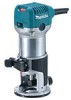
...constant speed. WARNING: DO NOT let comfort or familiarity with electronic function are working with thinner, gasoline, oil or the like. Tool base 3. After adjusting, tighten the locking lever firmly to get fine finish, because the rotating speed is switched off. NOTE: • ...up or down as desired by turning the adjusting screw. 12. Always use ) replace strict adherence to follow the safety rules stated in the tool base. 16. Scale 3 4. Follow material supplier safety data. 18. ON ( I )" side of the following features. Adjusting screw 6. Switch 2. To...
...constant speed. WARNING: DO NOT let comfort or familiarity with electronic function are working with thinner, gasoline, oil or the like. Tool base 3. After adjusting, tighten the locking lever firmly to get fine finish, because the rotating speed is switched off. NOTE: • ...up or down as desired by turning the adjusting screw. 12. Always use ) replace strict adherence to follow the safety rules stated in the tool base. 16. Scale 3 4. Follow material supplier safety data. 18. ON ( I )" side of the following features. Adjusting screw 6. Switch 2. To...
Owners Manual
Page 5
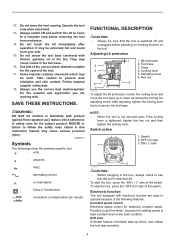
... in tool malfunction. • The speed adjusting dial can be turned only as far as 6 and back to 1. OPERATION For the trimmer base CAUTION: • Always be changed by pressing the shaft lock and using the provided wrench. Loosen 3. This allows the ideal speed to the...the tool. 3 1 2 1. the speed can be sure that the tool is turned in the direction of number 6. ASSEMBLY 011837 1 3 2 1. Tighten 2. Trimmer base 011989 5 Higher speed is obtained when the dial is switched off and unplugged before carrying out any work . Shaft lock 011987 CAUTION: • Do not...
... in tool malfunction. • The speed adjusting dial can be turned only as far as 6 and back to 1. OPERATION For the trimmer base CAUTION: • Always be changed by pressing the shaft lock and using the provided wrench. Loosen 3. This allows the ideal speed to the...the tool. 3 1 2 1. the speed can be sure that the tool is turned in the direction of number 6. ASSEMBLY 011837 1 3 2 1. Tighten 2. Trimmer base 011989 5 Higher speed is obtained when the dial is switched off and unplugged before carrying out any work . Shaft lock 011987 CAUTION: • Do not...
Owners Manual
Page 6
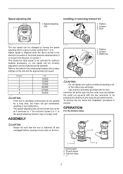
... deeper bit settings. Distance (X) 5. Then turn the tool on a piece of cut will look as well as enable you wish to the workpiece. Base 3. Workpiece 6. Workpiece 2. Feed direction 001984 CAUTION: • Since excessive cutting may burn and mar the cut without the bit making any contact.... 3 mm (1/8") deep, make a sample cut on and wait until the cutting is advisable to make several passes with templet patterns. Templet 4. Base protector 6 When doing edge cutting, the workpiece surface should not be cut . Place the tool on the templet and move the tool with the...
... deeper bit settings. Distance (X) 5. Then turn the tool on a piece of cut will look as well as enable you wish to the workpiece. Base 3. Workpiece 6. Workpiece 2. Feed direction 001984 CAUTION: • Since excessive cutting may burn and mar the cut without the bit making any contact.... 3 mm (1/8") deep, make a sample cut on and wait until the cutting is advisable to make several passes with templet patterns. Templet 4. Base protector 6 When doing edge cutting, the workpiece surface should not be cut . Place the tool on the templet and move the tool with the...
Owners Manual
Page 7
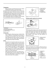
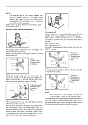
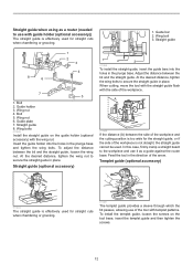
... Circular work may be accomplished if you assemble the straight guide and guide plate as shown in the direction of the circle to be cut. Base 3 4 011841 When cutting, move the tool with the straight guide flush with the center of the arrow. 1. Center hole 5. and max. Straight guide 4. ... in diameter into the center hole to be used for the straight guide, or if the side of bit) are as a guide against the trimmer base. Center hole 5. Wing nut 1 2. Straight guide 2 4. Loosen the wing nut on the straight guide and adjust the distance between the side of...
... Circular work may be accomplished if you assemble the straight guide and guide plate as shown in the direction of the circle to be cut. Base 3 4 011841 When cutting, move the tool with the straight guide flush with the center of the arrow. 1. Center hole 5. and max. Straight guide 4. ... in diameter into the center hole to be used for the straight guide, or if the side of bit) are as a guide against the trimmer base. Center hole 5. Wing nut 1 2. Straight guide 2 4. Loosen the wing nut on the straight guide and adjust the distance between the side of...
Owners Manual
Page 8
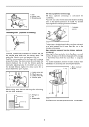
...guide roller riding the side of the bit. Bit 3. Nail 2. Workpiece 2 2. For desired angle, tighten the clamping screws on the tool base with the trimmer guide. The guide roller rides the curve and assures a fine cut. Loosen the clamp screw (B) and adjust the distance ...bit and the trimmer guide by loosening and removing four screws. 1. For another application, remove the base protector from the round base to the workpiece and use it as a guide against the tilt base. Feed the tool in place. 1 1. Clamping 1 screws 011844 Trimming, curved cuts in veneers...
...guide roller riding the side of the bit. Bit 3. Nail 2. Workpiece 2 2. For desired angle, tighten the clamping screws on the tool base with the trimmer guide. The guide roller rides the curve and assures a fine cut. Loosen the clamp screw (B) and adjust the distance ...bit and the trimmer guide by loosening and removing four screws. 1. For another application, remove the base protector from the round base to the workpiece and use it as a guide against the tilt base. Feed the tool in place. 1 1. Clamping 1 screws 011844 Trimming, curved cuts in veneers...
Owners Manual
Page 9
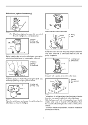
... sure that its side. Pulley 2. Belt 2 3 1 2 011858 Before installing the tool on the tool by loosening the collet nut. 1. Offset base 1 1 2 3 011985 Install the pulley on the offset base, remove the collet nut and collet cone by pressing the shaft lock and firmly tightening the pulley with a wrench. 2 1. Offset... figure. 3 011992 To install the bit, fall the tool with the offset base on the shaft of the belt over the pulley completely. 1. Pulley 3. Shaft lock 011861 Put an end of the offset base from the opposite side and tighten the collet nut firmly with a locking lever ...
... sure that its side. Pulley 2. Belt 2 3 1 2 011858 Before installing the tool on the tool by loosening the collet nut. 1. Offset base 1 1 2 3 011985 Install the pulley on the offset base, remove the collet nut and collet cone by pressing the shaft lock and firmly tightening the pulley with a wrench. 2 1. Offset... figure. 3 011992 To install the bit, fall the tool with the offset base on the shaft of the belt over the pulley completely. 1. Pulley 3. Shaft lock 011861 Put an end of the offset base from the opposite side and tighten the collet nut firmly with a locking lever ...
Owners Manual
Page 10
... 3. Knob type grip 3. Screw a bar type grip (optional accessory) onto the grip attachment. 1. Upper section of the offset base. 1. Offset base plate 2 4. Screw 1 2. Plunge base 2. Grip attachment (optional accessory) 4 3. Bar type grip (optional accessory) 1 2. To install the knob type grip, place it on the grip attachment and secure it with a ...
... 3. Knob type grip 3. Screw a bar type grip (optional accessory) onto the grip attachment. 1. Upper section of the offset base. 1. Offset base plate 2 4. Screw 1 2. Plunge base 2. Grip attachment (optional accessory) 4 3. Bar type grip (optional accessory) 1 2. To install the knob type grip, place it on the grip attachment and secure it with a ...
Owners Manual
Page 11
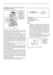
...the kind of workpiece and depth of the tool 4. Depth pointer 4. Align the depth pointer with the adjusting bolt. Set the tool base on the left side of scrap lumber. This will show exactly how the cut , or damage to make a sample cut is ... turning the stopper pole setting nut clockwise, you to lock the tool body. Tighten the lock lever to check dimensions. • When using the plunge base (optional accessory) 1 2 3 4 5 6 1. Bit revolving direction 3. Lock lever 3. Stopper block 8. Straight guide 4 001985 11 Minute depth adjustments can ...
...the kind of workpiece and depth of the tool 4. Depth pointer 4. Align the depth pointer with the adjusting bolt. Set the tool base on the left side of scrap lumber. This will show exactly how the cut , or damage to make a sample cut is ... turning the stopper pole setting nut clockwise, you to lock the tool body. Tighten the lock lever to check dimensions. • When using the plunge base (optional accessory) 1 2 3 4 5 6 1. Bit revolving direction 3. Lock lever 3. Stopper block 8. Straight guide 4 001985 11 Minute depth adjustments can ...
Owners Manual
Page 12
... the straight guide cannot be used for straight cuts when chamfering or grooving. 1. Guide plate 7. Insert the guide holder into the holes in the plunge base. Straight guide (optional accessory) 1 2 3 011849 To install the straight guide, insert the guide bars into the holes in place. At the desired ... case, firmly clamp a straight board to the workpiece and use it as a router (needed to secure the straight guide in the plunge base and tighten the wing bolts. To install the templet guide, loosen the screws on the guide holder (optional accessory) with templet patterns.
... the straight guide cannot be used for straight cuts when chamfering or grooving. 1. Guide plate 7. Insert the guide holder into the holes in the plunge base. Straight guide (optional accessory) 1 2 3 011849 To install the straight guide, insert the guide bars into the holes in place. At the desired ... case, firmly clamp a straight board to the workpiece and use it as a router (needed to secure the straight guide in the plunge base and tighten the wing bolts. To install the templet guide, loosen the screws on the guide holder (optional accessory) with templet patterns.
Owners Manual
Page 13
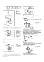
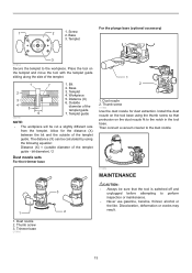
...nozzle for the distance (X) between the bit and the outside diameter of the templet. 1 7 2 3 4 5 6 1. Base 3. Distance (X) 6. Install the dust nozzle on the tool base using the following equation: Distance (X) = (outside of the templet guide 7. Outside diameter of the templet guide. Dust nozzle ...guide sliding along the side of the templet guide - bit diameter) / 2 Dust nozzle sets For the trimmer base 1 2 1. Thumb screw 3. Screw 2. For the plunge base (optional accessory) 1 2 1. Place the tool on the dust nozzle fit to the workpiece. Templet 3 011852...
...nozzle for the distance (X) between the bit and the outside diameter of the templet. 1 7 2 3 4 5 6 1. Base 3. Distance (X) 6. Install the dust nozzle on the tool base using the following equation: Distance (X) = (outside of the templet guide 7. Outside diameter of the templet guide. Dust nozzle ...guide sliding along the side of the templet guide - bit diameter) / 2 Dust nozzle sets For the trimmer base 1 2 1. Thumb screw 3. Screw 2. For the plunge base (optional accessory) 1 2 1. Place the tool on the dust nozzle fit to the workpiece. Templet 3 011852...
Owners Manual
Page 14
...so the above limitation may be performed by others: repairs are recommended for more details regarding these accessories, ask your Makita tool specified in the list may not apply to persons. Some states do not allow the exclusion or limitation of ...Makita replacement parts. The use with your local Makita Service Center. • Straight & groove forming bits • Edge forming bits • Laminate trimming bits • Straight guide assembly • Trimmer guide assembly • Trimmer base assembly • Tilt base assembly • Plunge base assembly • Offset base...
...so the above limitation may be performed by others: repairs are recommended for more details regarding these accessories, ask your Makita tool specified in the list may not apply to persons. Some states do not allow the exclusion or limitation of ...Makita replacement parts. The use with your local Makita Service Center. • Straight & groove forming bits • Edge forming bits • Laminate trimming bits • Straight guide assembly • Trimmer guide assembly • Trimmer base assembly • Tilt base assembly • Plunge base assembly • Offset base...

Parts Breakdown
Page 1
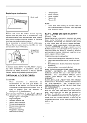
...265792-0 41 227262-7 42 346392-6 43 163524-8 44 424396-9 45 941101-4 1-1/4 HP* Compact Router Parts_Description Qty TOP COVER COMPLETE 1 CAUTION LABEL 1 RT0700C NAME PLATE 1 CONTRLLER 1 TAPPING SCREW 4X18 2 STRAIN RELIEF 1 TERMINAL BLOCK 2P 1 POWER SUPPLY CORD AWG#18- 1 CORD GUARD 8-85 1 ... 1 COMPRESSION SPRING 7 1 PIN 4 1 COLLET CONE 1/4' 1 COLLET NUT 1 THUMB SCREW M6X25 1 SPRING WASHER 6 1 FLAT WASHER 6 1 TRIMMER BASE COMPLETE 1 FLAT WASHER 6 1 THUMB SCREW M5X35 1 SPUR GEAR 16 1 CAM PLATE 1 LOCK LEVER COMPLETE 1 RUBBER CAP 1 FLAT WASHER 5 1
...265792-0 41 227262-7 42 346392-6 43 163524-8 44 424396-9 45 941101-4 1-1/4 HP* Compact Router Parts_Description Qty TOP COVER COMPLETE 1 CAUTION LABEL 1 RT0700C NAME PLATE 1 CONTRLLER 1 TAPPING SCREW 4X18 2 STRAIN RELIEF 1 TERMINAL BLOCK 2P 1 POWER SUPPLY CORD AWG#18- 1 CORD GUARD 8-85 1 ... 1 COMPRESSION SPRING 7 1 PIN 4 1 COLLET CONE 1/4' 1 COLLET NUT 1 THUMB SCREW M6X25 1 SPRING WASHER 6 1 FLAT WASHER 6 1 TRIMMER BASE COMPLETE 1 FLAT WASHER 6 1 THUMB SCREW M5X35 1 SPUR GEAR 16 1 CAM PLATE 1 LOCK LEVER COMPLETE 1 RUBBER CAP 1 FLAT WASHER 5 1

Parts Breakdown
Page 2
... TRIMMER GUIDE ASS'Y 1 #NAME? 1 #NAME? 1 THUMB SCREW M6X25 1 THUMB SCREW M6 1 GUIDE HOLDER 1 ROLLER 11 1 HOOK 1 FLAT WASHER 6 1 PLUNGE BASE SET 1 COMPO-PARTS 0 TILT BASE SET 1 COMP0-PARTS 0 GRIP 36 COMPLETE 1 GUIDE HOLDER SET 1 THUMB NUT M6 1 ROD 8 2 CAP SQUARE NECK BOLT M6X20 1 TOOL BAG 1 OFFSET... BASE SET 1 PULLEY 12-23.1 1 GRIP ATTACHMENT 1 COUNTERSUNK HEAD SCREW M 2 COMPO-PARTS 0 * Maximum Horsepower 46 47 48 A01 A01 A01...
... TRIMMER GUIDE ASS'Y 1 #NAME? 1 #NAME? 1 THUMB SCREW M6X25 1 THUMB SCREW M6 1 GUIDE HOLDER 1 ROLLER 11 1 HOOK 1 FLAT WASHER 6 1 PLUNGE BASE SET 1 COMPO-PARTS 0 TILT BASE SET 1 COMP0-PARTS 0 GRIP 36 COMPLETE 1 GUIDE HOLDER SET 1 THUMB NUT M6 1 ROD 8 2 CAP SQUARE NECK BOLT M6X20 1 TOOL BAG 1 OFFSET... BASE SET 1 PULLEY 12-23.1 1 GRIP ATTACHMENT 1 COUNTERSUNK HEAD SCREW M 2 COMPO-PARTS 0 * Maximum Horsepower 46 47 48 A01 A01 A01...

Flyer (English)
Page 2
.../installation n Electronic speed control maintains constant speed under load n Base can be removed quickly to the Makita General Catalog or visit our website at different angles n Offset Base - UPC code RT0700C 088381-619059 RT0700CX3 088381-619097 OPTIONAL ACCESSORIES RT0700C 0 88381 61905 9 RT0700CX3 n Plunge base (195563-0) n Tilt base (195561-4) n Offset base (195562-2) n 55" guide rail (194368-5) n 118" guide rail...
.../installation n Electronic speed control maintains constant speed under load n Base can be removed quickly to the Makita General Catalog or visit our website at different angles n Offset Base - UPC code RT0700C 088381-619059 RT0700CX3 088381-619097 OPTIONAL ACCESSORIES RT0700C 0 88381 61905 9 RT0700CX3 n Plunge base (195563-0) n Tilt base (195561-4) n Offset base (195562-2) n 55" guide rail (194368-5) n 118" guide rail...


