

Owners Manual
Page 2
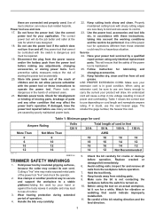
..., oil, sharp edges or moving parts. 16. Do not use any way. Do not expose power tools to lose control. Use of a cord suitable for the connection of electric shock. 7. ENGLISH (Original instructions) SPECIFICATIONS Model RT0700C Collet chuck capacity 1/4", 3/8" No load speed (RPM) 10,000 - 30,000/min. Use of an GFCI reduces the risk of electric shock. 8. Failure to a rotating part of electric shock if your mains-operated (corded) power tool or battery-operated (cordless) power tool. Damaged...
..., oil, sharp edges or moving parts. 16. Do not use any way. Do not expose power tools to lose control. Use of a cord suitable for the connection of electric shock. 7. ENGLISH (Original instructions) SPECIFICATIONS Model RT0700C Collet chuck capacity 1/4", 3/8" No load speed (RPM) 10,000 - 30,000/min. Use of an GFCI reduces the risk of electric shock. 8. Failure to a rotating part of electric shock if your mains-operated (corded) power tool or battery-operated (cordless) power tool. Damaged...
Owners Manual
Page 3
... the bit rotating direction and the feed direction. 3 If in doubt, use and care 17. Cutting a "live" wire may contact its own cord. Hold the tool firmly. 8. Before using only identical replacement parts. these are dangerous in the hands of untrained users. 21. The correct power tool will draw. Any power tool that the safety of the power tool is dangerous and must be controlled with these instructions to loss of operation...
... the bit rotating direction and the feed direction. 3 If in doubt, use and care 17. Cutting a "live" wire may contact its own cord. Hold the tool firmly. 8. Before using only identical replacement parts. these are dangerous in the hands of untrained users. 21. The correct power tool will draw. Any power tool that the safety of the power tool is dangerous and must be controlled with these instructions to loss of operation...
Owners Manual
Page 4
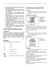
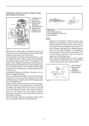
... turning the adjusting screw. Follow material supplier safety data. 18. Locking lever 5. NOTE: • When the tool is not secured even if the locking lever is kept constant even under load condition. SAVE THESE INSTRUCTIONS. Possible to a complete stop the tool, press the "OFF (O)" side of the tool. 17. Hex nut 4 5 6 011834 To adjust the bit protrusion, loosen the locking lever and move the tool base up shock, and makes the tool start...
... turning the adjusting screw. Follow material supplier safety data. 18. Locking lever 5. NOTE: • When the tool is not secured even if the locking lever is kept constant even under load condition. SAVE THESE INSTRUCTIONS. Possible to a complete stop the tool, press the "OFF (O)" side of the tool. 17. Hex nut 4 5 6 011834 To adjust the bit protrusion, loosen the locking lever and move the tool base up shock, and makes the tool start...
Owners Manual
Page 5
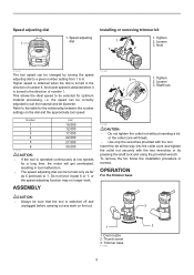
... longer work on the dial and the approximate tool speed. This allows the ideal speed to the table for a long time, the motor will break. • Use only the wrenches provided with the two wrenches or by turning the speed adjusting dial to a given number setting from 1 to suit the material and bit diameter. ASSEMBLY 011837 1 3 2 1. To remove the bit, follow the installation procedure in the direction of number 6. Dust nozzle 2. Thumb screw 3.
... longer work on the dial and the approximate tool speed. This allows the ideal speed to the table for a long time, the motor will break. • Use only the wrenches provided with the two wrenches or by turning the speed adjusting dial to a given number setting from 1 to suit the material and bit diameter. ASSEMBLY 011837 1 3 2 1. To remove the bit, follow the installation procedure in the direction of number 6. Dust nozzle 2. Thumb screw 3.
Owners Manual
Page 6
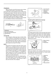
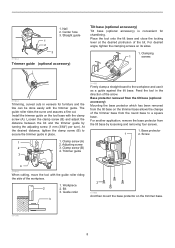
... direction. 1 4 2 3 2 4 2 1 1. Screws 3 3. Templet 4. Workpiece 6. Templet guide 10 7. When doing edge cutting, the workpiece surface should not be more than 3 mm (1/8") at a pass when cutting grooves. Workpiece 2. When you to check dimensions. • When using the tool with the trimmer base, always install the dust nozzle on the bit size, the kind of workpiece and depth of cut should be on the base and replace the base protector. Moving the tool...
... direction. 1 4 2 3 2 4 2 1 1. Screws 3 3. Templet 4. Workpiece 6. Templet guide 10 7. When doing edge cutting, the workpiece surface should not be more than 3 mm (1/8") at a pass when cutting grooves. Workpiece 2. When you to check dimensions. • When using the tool with the trimmer base, always install the dust nozzle on the bit size, the kind of workpiece and depth of cut should be on the base and replace the base protector. Moving the tool...
Owners Manual
Page 7
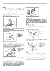
... hole to the straight guide with the clamp screw (A). Drive a nail less than 6 mm (1/4") in the straight guide with the side of bit) are as a guide against the trimmer base. Pivot the tool around the nail in radius cannot be used for the straight guide, or if the side of the arrow. 1. The distance (X) can be calculated by using this case, firmly clamp a straight board to...
... hole to the straight guide with the clamp screw (A). Drive a nail less than 6 mm (1/4") in the straight guide with the side of bit) are as a guide against the trimmer base. Pivot the tool around the nail in radius cannot be used for the straight guide, or if the side of the arrow. 1. The distance (X) can be calculated by using this case, firmly clamp a straight board to...
Owners Manual
Page 8
... the clamp screw (A). Place the tool onto the tilt base and close the locking lever at the desired protrusion of the workpiece. 1. Guide roller 3 1 2 011994 And then mount the base protector on its sides. 1. 1. Center hole 3. Adjusting screw 2 3. Screw 4 011845 When cutting, move the tool with the guide roller riding the side of the bit. Nail 2. For desired angle, tighten the clamping screws on the trimmer base. 001998 8 Clamping 1 screws 011844 Trimming, curved cuts in...
... the clamp screw (A). Place the tool onto the tilt base and close the locking lever at the desired protrusion of the workpiece. 1. Guide roller 3 1 2 011994 And then mount the base protector on its sides. 1. 1. Center hole 3. Adjusting screw 2 3. Screw 4 011845 When cutting, move the tool with the guide roller riding the side of the bit. Nail 2. For desired angle, tighten the clamping screws on the trimmer base. 001998 8 Clamping 1 screws 011844 Trimming, curved cuts in...
Owners Manual
Page 9
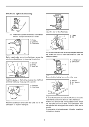
... the pulley using a screwdriver and make sure that position, insert the bit into the hole in reverse. 9 Offset base 1 1 2 3 011985 Install the pulley on the offset base, remove the collet nut and collet cone by pressing the shaft lock and firmly tightening the pulley with a wrench. Pulley 2. Belt 2 3 1 2 011858 Before installing the tool on the tool by loosening the collet nut. 1. To remove the bit at replacement, follow the installation procedure...
... the pulley using a screwdriver and make sure that position, insert the bit into the hole in reverse. 9 Offset base 1 1 2 3 011985 Install the pulley on the offset base, remove the collet nut and collet cone by pressing the shaft lock and firmly tightening the pulley with a wrench. Pulley 2. Belt 2 3 1 2 011858 Before installing the tool on the tool by loosening the collet nut. 1. To remove the bit at replacement, follow the installation procedure...
Owners Manual
Page 10
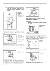
... the offset base plate. Knob type grip 3. Offset base plate 3. Knob 1 2 011856 To use the tool as a router, hold the tool firmly with a plunge base (optional accessory) CAUTION: • When using as a router, install the tool on a plunge base (optional accessory) by pressing it with two screws on the grip attachment and secure it down fully. Screw a bar type grip (optional accessory) onto the grip attachment. 1. Offset base plate 2 011986 When using as a router only with both hands. 1.
... the offset base plate. Knob type grip 3. Offset base plate 3. Knob 1 2 011856 To use the tool as a router, hold the tool firmly with a plunge base (optional accessory) CAUTION: • When using as a router, install the tool on a plunge base (optional accessory) by pressing it with two screws on the grip attachment and secure it down fully. Screw a bar type grip (optional accessory) onto the grip attachment. 1. Offset base plate 2 011986 When using as a router only with both hands. 1.
Owners Manual
Page 11
Lock lever 3. Stopper pole setting nut 5. Fast-feed button 6. Always firmly hold the tool by turning the adjusting knob (1 mm per turn the tool on the workpiece to check dimensions. • When using the plunge base (optional accessory) 1 2 3 4 5 6 1. When doing edge cutting, the workpiece surface should be on the right side in the feed direction. 1 4 2 3 2 4 1. View from the top of cut is advisable to lock the tool body. This will show exactly...
Lock lever 3. Stopper pole setting nut 5. Fast-feed button 6. Always firmly hold the tool by turning the adjusting knob (1 mm per turn the tool on the workpiece to check dimensions. • When using the plunge base (optional accessory) 1 2 3 4 5 6 1. When doing edge cutting, the workpiece surface should be on the right side in the feed direction. 1 4 2 3 2 4 1. View from the top of cut is advisable to lock the tool body. This will show exactly...
Owners Manual
Page 12
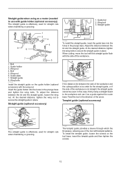
... this case, firmly clamp a straight board to the workpiece and use it as a router (needed to secure the straight guide in place. Wing bolts 011988 Install the straight guide on the tool base, insert the templet guide and then tighten the screws. 12 Insert the guide holder into the holes in the direction of the workpiece. A 011850 If the distance (A) between the bit and the straight guide. Wing nut 4. Bolt 5. To adjust...
... this case, firmly clamp a straight board to the workpiece and use it as a router (needed to secure the straight guide in place. Wing bolts 011988 Install the straight guide on the tool base, insert the templet guide and then tighten the screws. 12 Insert the guide holder into the holes in the direction of the workpiece. A 011850 If the distance (A) between the bit and the straight guide. Wing nut 4. Bolt 5. To adjust...
Owners Manual
Page 13
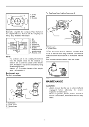
... the dust nozzle. 011854 MAINTENANCE 1 1. Base 3. Trimmer base 011989 3 2 CAUTION: • Always be cut a slightly different size from the templet. For the plunge base (optional accessory) 1 2 1. Base 3. Templet 4. Outside diameter of the templet guide - The distance (X) can be calculated by using the thumb screw so that the tool is switched off and unplugged before attempting to the notch in the tool base. Thumb screw 011853 Use the dust nozzle...
... the dust nozzle. 011854 MAINTENANCE 1 1. Base 3. Trimmer base 011989 3 2 CAUTION: • Always be cut a slightly different size from the templet. For the plunge base (optional accessory) 1 2 1. Base 3. Templet 4. Outside diameter of the templet guide - The distance (X) can be calculated by using the thumb screw so that the tool is switched off and unplugged before attempting to the notch in the tool base. Thumb screw 011853 Use the dust nozzle...
Owners Manual
Page 14
.... Screwdriver 2. MAKITA LIMITED ONE YEAR WARRANTY Warranty Policy Every Makita tool is caused by Makita Authorized or Factory Service Centers, always using Makita replacement parts. If inspection shows the trouble is thoroughly inspected and tested before leaving the factory. Replace when they wear down to slip in the holders. Keep the carbon brushes clean and free to the limit mark. Brush holder cap 1 2 011846 To maintain product SAFETY and RELIABILITY, repairs, any...
.... Screwdriver 2. MAKITA LIMITED ONE YEAR WARRANTY Warranty Policy Every Makita tool is caused by Makita Authorized or Factory Service Centers, always using Makita replacement parts. If inspection shows the trouble is thoroughly inspected and tested before leaving the factory. Replace when they wear down to slip in the holders. Keep the carbon brushes clean and free to the limit mark. Brush holder cap 1 2 011846 To maintain product SAFETY and RELIABILITY, repairs, any...

Parts Breakdown
Page 1
... 1 POWER SUPPLY CORD AWG#18- 1 CORD GUARD 8-85 1 BRUSH HOLDER CAP 5-8 2 CARBON BRUSH CB-408 1 BRACKET COMPLETE 1 BRUSH HOLDER 6X9 2 SWITCH 1 FIELD 115V 1 TAPPING SCREW 4X65 2 SELF LOCK 6 1 MAGNET SLEEVE 1 THIN WASHER 6 1 WAVE WASHER 6 1 BALL BEARING 627DDW 1 RESIN WASHER 1 ARMATURE ASS'Y 115V 1 INC. 17-2224-26 0 FAN 55 1 RETAINING RING S-17 1 BALL BEARING 6003DDW 1 WAVE WASHER 26 1 OUTER HOUSING COMPLETE 1 TAPPING SCREW 4X40 4 PUSH BUTTON 1 COMPRESSION SPRING 7 1 PIN 4 1 COLLET CONE 1/4' 1 COLLET NUT...
... 1 POWER SUPPLY CORD AWG#18- 1 CORD GUARD 8-85 1 BRUSH HOLDER CAP 5-8 2 CARBON BRUSH CB-408 1 BRACKET COMPLETE 1 BRUSH HOLDER 6X9 2 SWITCH 1 FIELD 115V 1 TAPPING SCREW 4X65 2 SELF LOCK 6 1 MAGNET SLEEVE 1 THIN WASHER 6 1 WAVE WASHER 6 1 BALL BEARING 627DDW 1 RESIN WASHER 1 ARMATURE ASS'Y 115V 1 INC. 17-2224-26 0 FAN 55 1 RETAINING RING S-17 1 BALL BEARING 6003DDW 1 WAVE WASHER 26 1 OUTER HOUSING COMPLETE 1 TAPPING SCREW 4X40 4 PUSH BUTTON 1 COMPRESSION SPRING 7 1 PIN 4 1 COLLET CONE 1/4' 1 COLLET NUT...

Parts Breakdown
Page 2
... HEAD SCREW M 4 STRAIGHT GUIDE ASSEMBLY 1 THUMB NUT M6 1 CAP SQUARE NECK BOLT M6X20 1 GUIDE PLATE 1 DUST NOZZLE SET 1 DUST NOZZLE SET 1 O RING 3 2 THUMB SCREW M4X19 1 THUMB SCREW M4X19 1 DUST NOZZLE SET 1 TEMPLET GUIDE 10 1 THUMB SCREW M4X19 1 TEMPLET GUIDE 10 1 COLLET CONE 3/8' 1 COLLET CONE 3/8' 1 WRENCH 22 1 WRENCH 13 1 WRENCH 22 1 WRENCH 13 1 TEMPLET GUIDE 16 1 TRIMMER GUIDE ASS'Y 1 #NAME? 1 #NAME? 1 THUMB SCREW M6X25 1 THUMB SCREW M6 1 GUIDE HOLDER 1 ROLLER 11 1 HOOK 1 FLAT WASHER 6 1 PLUNGE BASE SET 1 COMPO-PARTS 0 TILT BASE...
... HEAD SCREW M 4 STRAIGHT GUIDE ASSEMBLY 1 THUMB NUT M6 1 CAP SQUARE NECK BOLT M6X20 1 GUIDE PLATE 1 DUST NOZZLE SET 1 DUST NOZZLE SET 1 O RING 3 2 THUMB SCREW M4X19 1 THUMB SCREW M4X19 1 DUST NOZZLE SET 1 TEMPLET GUIDE 10 1 THUMB SCREW M4X19 1 TEMPLET GUIDE 10 1 COLLET CONE 3/8' 1 COLLET CONE 3/8' 1 WRENCH 22 1 WRENCH 13 1 WRENCH 22 1 WRENCH 13 1 TEMPLET GUIDE 16 1 TRIMMER GUIDE ASS'Y 1 #NAME? 1 #NAME? 1 THUMB SCREW M6X25 1 THUMB SCREW M6 1 GUIDE HOLDER 1 ROLLER 11 1 HOOK 1 FLAT WASHER 6 1 PLUNGE BASE SET 1 COMPO-PARTS 0 TILT BASE...

Flyer (English)
Page 1
... ROUTER/ KIT POWER POWERFUL 1-1/4 HP* MOTOR DELIVERS 6.5 AMP FOR IMPROVED PERFORMANCE • Variable Speed Control Dial (10,000 - 30,000 RPM) Enables User to Match the Speed to the Application • Smooth Rack-and-Pinion Fine Depth Adjustment System for More Precise Settings • Slim and Ergonomically Designed Body for Increased Comfort and Control • Quick Release Cam Lock System for Convenient Depth Adjustments • Electronic Speed...
... ROUTER/ KIT POWER POWERFUL 1-1/4 HP* MOTOR DELIVERS 6.5 AMP FOR IMPROVED PERFORMANCE • Variable Speed Control Dial (10,000 - 30,000 RPM) Enables User to Match the Speed to the Application • Smooth Rack-and-Pinion Fine Depth Adjustment System for More Precise Settings • Slim and Ergonomically Designed Body for Increased Comfort and Control • Quick Release Cam Lock System for Convenient Depth Adjustments • Electronic Speed...

Flyer (English)
Page 2
...-7) n Guide rail adapter (194579-2) n Guide rail clamp set (194385-5) Makita offers a wide variety of Makita Corporation." All models and accessories subject to install other bases (plunge, tilt and offset) RT0700CX3 - 1-1/4 HP* COMPACT ROUTER/ KIT RT0700C/ RT0700CX3 FEATURES & BENEFITS n Powerful 1-1/4 HP* motor delivers 6.5 AMP for improved performance n Variable speed control dial (10,000 - 30,000 RPM) enables user to match the speed to the application n Smooth rack-and-pinion fine depth adjustment system...
...-7) n Guide rail adapter (194579-2) n Guide rail clamp set (194385-5) Makita offers a wide variety of Makita Corporation." All models and accessories subject to install other bases (plunge, tilt and offset) RT0700CX3 - 1-1/4 HP* COMPACT ROUTER/ KIT RT0700C/ RT0700CX3 FEATURES & BENEFITS n Powerful 1-1/4 HP* motor delivers 6.5 AMP for improved performance n Variable speed control dial (10,000 - 30,000 RPM) enables user to match the speed to the application n Smooth rack-and-pinion fine depth adjustment system...


