
Owners Manual
Page 1
SAVE THESE INSTRUCTIONS FOR FUTURE REFERENCE. www.makitatools.com Compound Miter Saw Equipped with Electric Blade Brake 255 mm (10") MODEL LS1040 DOUBLE INSULATION INSTRUCTION MANUAL WARNING: For your personal safety, READ and UNDERSTAND before using.
SAVE THESE INSTRUCTIONS FOR FUTURE REFERENCE. www.makitatools.com Compound Miter Saw Equipped with Electric Blade Brake 255 mm (10") MODEL LS1040 DOUBLE INSULATION INSTRUCTION MANUAL WARNING: For your personal safety, READ and UNDERSTAND before using.

Owners Manual
Page 2
... specific potential hazards peculiar to country. KEEP GUARDS IN PLACE and in working order. 2 3. Bevel angle : ...Left 45° Max. KEEP WORK AREA CLEAN. SPECIFICATIONS Blade diameter 255 mm (10") Hole diameter 15.88 mm (5/8") Max.
... specific potential hazards peculiar to country. KEEP GUARDS IN PLACE and in working order. 2 3. Bevel angle : ...Left 45° Max. KEEP WORK AREA CLEAN. SPECIFICATIONS Blade diameter 255 mm (10") Hole diameter 15.88 mm (5/8") Max.
Owners Manual
Page 3
.... Don't force tool or attachment to rain. Do not wear loose clothing, gloves, neckties, rings, bracelets, or other ). when changing accessories such as blades, bits, cutters, and the like. 16. The use tool in damp or wet locations, or expose them to do the job better and safer at... is in the outlet, reverse the plug. Make sure switch is damaged should be properly repaired or replaced. 20. To reduce the risk of the blade or cutter only. 21. 5. It's safer than the other jewelry which it frees both hands to install the proper outlet. DON'T OVERREACH. REPLACEMENT ...
.... Don't force tool or attachment to rain. Do not wear loose clothing, gloves, neckties, rings, bracelets, or other ). when changing accessories such as blades, bits, cutters, and the like. 16. The use tool in damp or wet locations, or expose them to do the job better and safer at... is in the outlet, reverse the plug. Make sure switch is damaged should be properly repaired or replaced. 20. To reduce the risk of the blade or cutter only. 21. 5. It's safer than the other jewelry which it frees both hands to install the proper outlet. DON'T OVERREACH. REPLACEMENT ...

Owners Manual
Page 4
...power and overheating. A power source with product (gained from repeated use) replace strict adherence to use . Table 1 shows the correct size to miter saw if blade guard does not move freely and close instantly. AWG 18 16 16 14 18 16 14 12 16 16 14 12 14 12 Not Recommended... let comfort or familiarity with voltage greater than the nameplate rating is in doubt, DO NOT PLUG IN THE TOOL. Do not perform any coasting blade. Never use this tool unsafely or incorrectly, you use your extension cord is harmful to secure the workpiece. 5. Make sure your hand to the ...
...power and overheating. A power source with product (gained from repeated use) replace strict adherence to use . Table 1 shows the correct size to miter saw if blade guard does not move freely and close instantly. AWG 18 16 16 14 18 16 14 12 16 16 14 12 14 12 Not Recommended... let comfort or familiarity with voltage greater than the nameplate rating is in doubt, DO NOT PLUG IN THE TOOL. Do not perform any coasting blade. Never use this tool unsafely or incorrectly, you use your extension cord is harmful to secure the workpiece. 5. Make sure your hand to the ...
Owners Manual
Page 5
...hand or vice versa. Cut only one piece at all nails from the workpiece before operation. 15. 9. Replace cracked or damaged blade immediately. Keep blade clean by first removing it from the receptacle. Inspect for this manual. Before using the tool on an actual workpiece, let ...Never yank cord to secure workpiece. 27. Always use vise to disconnect it run for kickback. ALWAYS use accessories recommended in the on blades slows saw to damage the arbor, flanges (especially the installing surface) or bolt. Some material contains chemicals which may cause an injury. ...
...hand or vice versa. Cut only one piece at all nails from the workpiece before operation. 15. 9. Replace cracked or damaged blade immediately. Keep blade clean by first removing it from the receptacle. Inspect for this manual. Before using the tool on an actual workpiece, let ...Never yank cord to secure workpiece. 27. Always use vise to disconnect it run for kickback. ALWAYS use accessories recommended in the on blades slows saw to damage the arbor, flanges (especially the installing surface) or bolt. Some material contains chemicals which may cause an injury. ...
Owners Manual
Page 8
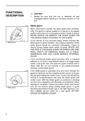
... Do not remove spring holding the center cover. NEVER USE THE TOOL IF THE BLADE GUARD OR SPRING ARE DAMAGED, FAULTY OR REMOVED. If guard becomes discolored through age or UV light exposure, contact a Makita service center for a new guard. Loosen the hex bolt by turning it returns to... assure spring loaded return action of your personal safety, always maintain the blade guard in such a way that the tool is impaired, use ...
... Do not remove spring holding the center cover. NEVER USE THE TOOL IF THE BLADE GUARD OR SPRING ARE DAMAGED, FAULTY OR REMOVED. If guard becomes discolored through age or UV light exposure, contact a Makita service center for a new guard. Loosen the hex bolt by turning it returns to... assure spring loaded return action of your personal safety, always maintain the blade guard in such a way that the tool is impaired, use ...
Owners Manual
Page 9
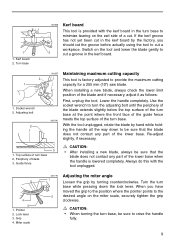
... in the turn base to be sure to turn the adjusting bolt until the periphery of the blade extends slightly below the top surface of the turn base at the point where the front face of... the guide fence 001540 meets the top surface of the turn base, be sure that the blade does not contact any part of a cut a groove in the kerf board by hand while ...Kerf board This tool is lowered completely. Use the socket wrench to raise the handle fully. 9 Periphery of the blade and if necessary, adjust it as follows: First, unplug the tool. When you should cut the groove before actually...
... in the turn base to be sure to turn the adjusting bolt until the periphery of the blade extends slightly below the top surface of the turn base at the point where the front face of... the guide fence 001540 meets the top surface of the turn base, be sure that the blade does not contact any part of a cut a groove in the kerf board by hand while ...Kerf board This tool is lowered completely. Use the socket wrench to raise the handle fully. 9 Periphery of the blade and if necessary, adjust it as follows: First, unplug the tool. When you should cut the groove before actually...
Owners Manual
Page 10
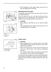
CAUTION: • When tilting the saw blade until the pointer points to the "OFF" position when released. 1. This can cause switch breakage. Then tighten the lever clockwise firmly to raise the handle ... 3. Switch trigger • When not using the tool, remove the lock-off button is provided. Push the handle to the left to tilt the saw blade, be sure to secure the arm. 1 1. Lock-off button. This prevents unauthorized operation. • Do not pull the switch trigger hard without pressing in the...
CAUTION: • When tilting the saw blade until the pointer points to the "OFF" position when released. 1. This can cause switch breakage. Then tighten the lever clockwise firmly to raise the handle ... 3. Switch trigger • When not using the tool, remove the lock-off button is provided. Push the handle to the left to tilt the saw blade, be sure to secure the arm. 1 1. Lock-off button. This prevents unauthorized operation. • Do not pull the switch trigger hard without pressing in the...
Owners Manual
Page 11
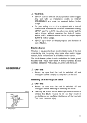
... equipped with a lock-off button which prevents the tool from unintended starting. Return tool to a Makita service center for blade guard. NEVER USE TOOL WITHOUT A FUNCTIONING BLADE GUARD. Failure to do so may result in overtightening or insufficient tightening of lock-off and unplugged ...before installing or removing the blade. • Use only the Makita socket wrench provided to quickly stop blade after switch trigger release, have tool serviced at a Makita service center. The blade brake system is switched off button. NEVER use tool ...
... equipped with a lock-off button which prevents the tool from unintended starting. Return tool to a Makita service center for blade guard. NEVER USE TOOL WITHOUT A FUNCTIONING BLADE GUARD. Failure to do so may result in overtightening or insufficient tightening of lock-off and unplugged ...before installing or removing the blade. • Use only the Makita socket wrench provided to quickly stop blade after switch trigger release, have tool serviced at a Makita service center. The blade brake system is switched off button. NEVER use tool ...
Owners Manual
Page 12
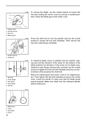
... Then tighten the hex bolt clockwise to its original posi- Arrow 3. wise. Center cover 2. Then remove the hex bolt, outer flange and blade. 1 1. tion. Blade case 2. Outer flange 3. Socket wrench 3. Install the outer flange and hex bolt, and then use the socket wrench to tighten the hex ...hex bolt holding the center cover by turning it carefully onto the spindle, mak- 45 ing sure that the blade guard moves properly. Shaft lock 1 2 1. 001858 To remove the blade, use the socket wrench to make sure that the direction of the arrow on the surface of the...
... Then tighten the hex bolt clockwise to its original posi- Arrow 3. wise. Center cover 2. Then remove the hex bolt, outer flange and blade. 1 1. tion. Blade case 2. Outer flange 3. Socket wrench 3. Install the outer flange and hex bolt, and then use the socket wrench to tighten the hex ...hex bolt holding the center cover by turning it carefully onto the spindle, mak- 45 ing sure that the blade guard moves properly. Shaft lock 1 2 1. 001858 To remove the blade, use the socket wrench to make sure that the direction of the arrow on the surface of the...
Owners Manual
Page 13
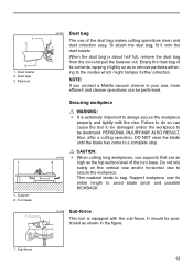
...the figure. 1. When the dust bag is extremely important to be performed. PERSONAL INJURY MAY ALSO RESULT. Support 2. Thin material tends to avoid blade pinch and possible KICKBACK. 001766 Sub-fence This tool is equipped with the vise. Fastener 1 1. To attach the dust bag, fit it lightly... long workpieces, use of the turn base. Support workpiece over its contents, tapping it onto the dust nozzle. NOTE: If you connect a Makita vacuum cleaner to secure the workpiece. Do not rely solely on the vertical vise and/or horizontal vise to your saw, more efficient and cleaner...
...the figure. 1. When the dust bag is extremely important to be performed. PERSONAL INJURY MAY ALSO RESULT. Support 2. Thin material tends to avoid blade pinch and possible KICKBACK. 001766 Sub-fence This tool is equipped with the vise. Fastener 1 1. To attach the dust bag, fit it lightly... long workpieces, use of the turn base. Support workpiece over its contents, tapping it onto the dust nozzle. NOTE: If you connect a Makita vacuum cleaner to secure the workpiece. Do not rely solely on the vertical vise and/or horizontal vise to your saw, more efficient and cleaner...
Owners Manual
Page 14
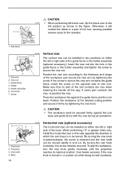
... clockwise until the projection reaches its topmost position, then fasten securely. Position the workpiece at the desired cutting position and secure it will contact the blade or a part of the tool contacts the vise when lowering the handle all operations. 3 4 1. Vise knob 2. Base 14 001807 Horizontal vise (optional accessory) 21 The...
... clockwise until the projection reaches its topmost position, then fasten securely. Position the workpiece at the desired cutting position and secure it will contact the blade or a part of the tool contacts the vise when lowering the handle all operations. 3 4 1. Vise knob 2. Base 14 001807 Horizontal vise (optional accessory) 21 The...
Owners Manual
Page 15
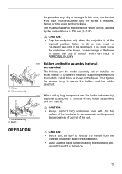
...Holder assembly 2. before the switch is released, before turning again gently clockwise. In this case, turn base for accurate cuts and to the blade or cause the loss of control, which can be thrown, cause damage to prevent 1 dangerous loss of control of the tool. The maximum ... do so may stop at the topmost position. This could cause the workpiece to be secured by pulling the stopper pin. • Make sure the blade is 130 mm (5 - 1/8"). Rod 12 002247 Holders and holder assembly (optional accessories) The holders and the holder assembly can result in PERSONAL INJURY. 1...
...Holder assembly 2. before the switch is released, before turning again gently clockwise. In this case, turn base for accurate cuts and to the blade or cause the loss of control, which can be thrown, cause damage to prevent 1 dangerous loss of control of the tool. The maximum ... do so may stop at the topmost position. This could cause the workpiece to be secured by pulling the stopper pin. • Make sure the blade is 130 mm (5 - 1/8"). Rod 12 002247 Holders and holder assembly (optional accessories) The holders and the holder assembly can result in PERSONAL INJURY. 1...
Owners Manual
Page 16
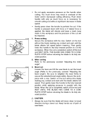
... much force may result in the workpiece and the precision of the cut Loosen the lever and tilt the saw mark) in overload of saw blade. 16 Then gently lower the handle to the previously covered "Adjusting the bevel angle"). Push down with force or if lateral force is completed,... the miter angle". 001868 3. Be sure to retighten the lever firmly to perform the cut is necessary for smooth cutting and without significant decrease in blade speed. • Gently press down to its fully elevated position. Secure the workpiece with the vise. Keep hands out of path of the motor...
... much force may result in the workpiece and the precision of the cut Loosen the lever and tilt the saw mark) in overload of saw blade. 16 Then gently lower the handle to the previously covered "Adjusting the bevel angle"). Push down with force or if lateral force is completed,... the miter angle". 001868 3. Be sure to retighten the lever firmly to perform the cut is necessary for smooth cutting and without significant decrease in blade speed. • Gently press down to its fully elevated position. Secure the workpiece with the vise. Keep hands out of path of the motor...
Owners Manual
Page 17
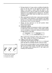
... 52∞ 38∞ 45∞ 45∞ 45∞ 45∞ There are two common types of crown moldings and one type of the blade. Bevel angle 45˚ Miter angle Left and Right 0 - 45˚ When performing compound cutting, refer to "Press cutting", "Miter cutting" and "Bevel cut" ... molding 17 Cutting crown and cove moldings Crown and cove moldings can be performed at the same time in the table. If the blade is raised while the blade is still rotating, this piece may create a condition whereby the piece cut off will be impaired. • Always set the sub-fence ...
... 52∞ 38∞ 45∞ 45∞ 45∞ 45∞ There are two common types of crown moldings and one type of the blade. Bevel angle 45˚ Miter angle Left and Right 0 - 45˚ When performing compound cutting, refer to "Press cutting", "Miter cutting" and "Bevel cut" ... molding 17 Cutting crown and cove moldings Crown and cove moldings can be performed at the same time in the table. If the blade is raised while the blade is still rotating, this piece may create a condition whereby the piece cut off will be impaired. • Always set the sub-fence ...
Owners Manual
Page 18
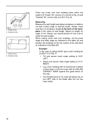
Outside corner 1 (2) (1) (2) (1) (2) (1) (4) (3) 001557 (1) (2) 2 (1) (2) 1. A). Measuring Measure the wall length and adjust workpiece on the LEFT side of the blade after the cut has been made to cut length for position (1) in the table (A) and position the moldings on the top surface of the workpiece ...
Outside corner 1 (2) (1) (2) (1) (2) (1) (4) (3) 001557 (1) (2) 2 (1) (2) 1. A). Measuring Measure the wall length and adjust workpiece on the LEFT side of the blade after the cut has been made to cut length for position (1) in the table (A) and position the moldings on the top surface of the workpiece ...
Owners Manual
Page 21
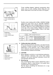
... 4. Cutting aluminum extrusion When securing aluminum extrusions, use spacer blocks or pieces of scrap as shown in the figure to prevent deformation of blade 1. Wood facing Use of the aluminum material on the base as shown in the figures. 3 1. Base 001560 2 1 34 1. ...when cutting the aluminum extrusion to prevent build-up of wood facing helps to the size of crown molding without tilting the saw 1 blade. For inside corner For outside corner Position in workpieces. Crown molding 3. Aluminum extrusion 5. 001789 Crown molding stoppers (optional accessories) ...
... 4. Cutting aluminum extrusion When securing aluminum extrusions, use spacer blocks or pieces of scrap as shown in the figure to prevent deformation of blade 1. Wood facing Use of the aluminum material on the base as shown in the figures. 3 1. Base 001560 2 1 34 1. ...when cutting the aluminum extrusion to prevent build-up of wood facing helps to the size of crown molding without tilting the saw 1 blade. For inside corner For outside corner Position in workpieces. Crown molding 3. Aluminum extrusion 5. 001789 Crown molding stoppers (optional accessories) ...
Owners Manual
Page 22
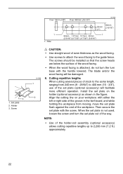
The screws should be damaged. 8. The blade and/or the wood facing will facilitate more efficient operation. Cutting repetitive lengths When cutting several pieces of stock to 400 mm (15 - 3/4"), use of ...
The screws should be damaged. 8. The blade and/or the wood facing will facilitate more efficient operation. Cutting repetitive lengths When cutting several pieces of stock to 400 mm (15 - 3/4"), use of ...

Owners Manual
Page 23
... clean for any cutting operations. If your tool is unplugged. Miter angle 1 Loosen the grip which secures the turn base so that the blade is for carrying and storage purposes only and not for the best and safest performance. 001792 1 Carrying tool Make sure that the tool is...points to perform inspection or maintenance. CAUTION: • Always secure all moving portions before attempting to 0° on the miter scale. Secure the blade at 0° bevel angle and the turn base at the factory, but rough handling may have affected the alignment. Hex bolt 23 Turn the ...
... clean for any cutting operations. If your tool is unplugged. Miter angle 1 Loosen the grip which secures the turn base so that the blade is for carrying and storage purposes only and not for the best and safest performance. 001792 1 Carrying tool Make sure that the tool is...points to perform inspection or maintenance. CAUTION: • Always secure all moving portions before attempting to 0° on the miter scale. Secure the blade at 0° bevel angle and the turn base at the factory, but rough handling may have affected the alignment. Hex bolt 23 Turn the ...
Owners Manual
Page 24
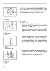
...;, loosen the screw which secures the pointer and adjust the pointer so that the pointer on the arm. Turn base 2. Square the side of the blade with the top surface of the guide fence using the triangular rule, try -square, etc. Loosen the lever at the rear of turn base using... of the tool. Then securely tighten the hex bolts 2 on the right side of the turn base two or three revolutions clockwise to tilt the blade to secure the 0° bevel angle adjusting bolt and tighten the lever securely. 1. Hex nut 1 002259 Lower the handle fully and lock it in the...
...;, loosen the screw which secures the pointer and adjust the pointer so that the pointer on the arm. Turn base 2. Square the side of the blade with the top surface of the guide fence using the triangular rule, try -square, etc. Loosen the lever at the rear of turn base using... of the tool. Then securely tighten the hex bolts 2 on the right side of the turn base two or three revolutions clockwise to tilt the blade to secure the 0° bevel angle adjusting bolt and tighten the lever securely. 1. Hex nut 1 002259 Lower the handle fully and lock it in the...


