
User Guide
Page 2
...of its contents. Netware® is the intellectual property of M ICRO-STAR INTERNATIONAL. AMI® is a registered trademark of Phoenix Technologies Ltd. Trademarks All trademarks are registered trademarks of International Business Machines Corporation. PS/2 and OS®/2 are the properties of their ...distributor. Copyright Notice The material in the preparation of this document is a registered trademark of American Megatrends Inc. Visit the MSI website for further guidance. W indows® 95/98/2000/NT/XP are registered trademarks or trademarks of NVIDIA Corporation ...
...of its contents. Netware® is the intellectual property of M ICRO-STAR INTERNATIONAL. AMI® is a registered trademark of Phoenix Technologies Ltd. Trademarks All trademarks are registered trademarks of International Business Machines Corporation. PS/2 and OS®/2 are the properties of their ...distributor. Copyright Notice The material in the preparation of this document is a registered trademark of American Megatrends Inc. Visit the MSI website for further guidance. W indows® 95/98/2000/NT/XP are registered trademarks or trademarks of NVIDIA Corporation ...
User Guide
Page 4
... is encouraged to try to correct the interference by the party responsible for compliance could void the user's authority to operate the equipment. Micro-Star International MS-7173 This device complies with the limits for help. These limits are designed to provide reasonable protection against harmful interference in a particular installation. VOIR...
... is encouraged to try to correct the interference by the party responsible for compliance could void the user's authority to operate the equipment. Micro-Star International MS-7173 This device complies with the limits for help. These limits are designed to provide reasonable protection against harmful interference in a particular installation. VOIR...
User Guide
Page 38
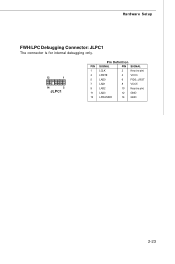
Hardware Setup FWH/LPC Debugging Connector: JLPC1 The connector is for internal debugging only. 13 1 14 2 JLPC1 Pin Definition PIN SIGNAL PIN SIGNAL 1 LCLK 2 Key (no pin) 3 LRST# 4 VCC3 5 LAD0 6 FID0_LRST 7 LAD1 8 VCC5 9 LAD2 10 Key(no pin) 11 LAD3 12 GND 13 LFRAME# 14 GND 2-23
Hardware Setup FWH/LPC Debugging Connector: JLPC1 The connector is for internal debugging only. 13 1 14 2 JLPC1 Pin Definition PIN SIGNAL PIN SIGNAL 1 LCLK 2 Key (no pin) 3 LRST# 4 VCC3 5 LAD0 6 FID0_LRST 7 LAD1 8 VCC5 9 LAD2 10 Key(no pin) 11 LAD3 12 GND 13 LFRAME# 14 GND 2-23
User Guide
Page 91
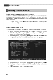
... the graphics card in addition to the CMOS Setup screen. Use the arrow keys to navigate to UM A. 4. Use the arrow keys to navigate to Internal Video M ode and set it to Advanced Chipset Features, and then press Enter. B-6 CMOS is enabled (using the BIOS setup utility) in the PCIe™...
... the graphics card in addition to the CMOS Setup screen. Use the arrow keys to navigate to UM A. 4. Use the arrow keys to navigate to Internal Video M ode and set it to Advanced Chipset Features, and then press Enter. B-6 CMOS is enabled (using the BIOS setup utility) in the PCIe™...
