
User Guide
Page 2
...our technical staff at: http://support.msi.com.tw ii AMD, Athlon™, Athlon™ XP, Thoroughbred™, and Duron™ are under continual improvement and we reserve the right to the correctness of M ICRO-STAR INTERNATIONAL. Our products are registered trademarks of...History PCB v2.X Date September 2006 Technical Support If a problem arises with your system and no guarantee is a registered trademark of International Business Machines Corporation. Alternatively, please try the following help resources for FAQ, technical guide, BIOS updates, driver updates, and other...
...our technical staff at: http://support.msi.com.tw ii AMD, Athlon™, Athlon™ XP, Thoroughbred™, and Duron™ are under continual improvement and we reserve the right to the correctness of M ICRO-STAR INTERNATIONAL. Our products are registered trademarks of...History PCB v2.X Date September 2006 Technical Support If a problem arises with your system and no guarantee is a registered trademark of International Business Machines Corporation. Alternatively, please try the following help resources for FAQ, technical guide, BIOS updates, driver updates, and other...
User Guide
Page 4
... for help. power cord, if any interference received, including interference that to Part 15 of the FCC Rules. Notice 2 Shielded interface cables and A.C. Micro-Star International MS-7173 This device complies with the instructions, may cause undesired operation.
... for help. power cord, if any interference received, including interference that to Part 15 of the FCC Rules. Notice 2 Shielded interface cables and A.C. Micro-Star International MS-7173 This device complies with the instructions, may cause undesired operation.
User Guide
Page 38
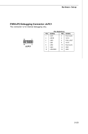
Hardware Setup FWH/LPC Debugging Connector: JLPC1 The connector is for internal debugging only. 13 1 14 2 JLPC1 Pin Definition PIN SIGNAL PIN SIGNAL 1 LCLK 2 Key (no pin) 3 LRST# 4 VCC3 5 LAD0 6 FID0_LRST 7 LAD1 8 VCC5 9 LAD2 10 Key(no pin) 11 LAD3 12 GND 13 LFRAME# 14 GND 2-23
Hardware Setup FWH/LPC Debugging Connector: JLPC1 The connector is for internal debugging only. 13 1 14 2 JLPC1 Pin Definition PIN SIGNAL PIN SIGNAL 1 LCLK 2 Key (no pin) 3 LRST# 4 VCC3 5 LAD0 6 FID0_LRST 7 LAD1 8 VCC5 9 LAD2 10 Key(no pin) 11 LAD3 12 GND 13 LFRAME# 14 GND 2-23
User Guide
Page 91
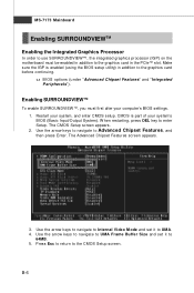
... sure the IGP is part of your system's BIOS (Basic Input/Output System). The CMOS Setup screen appears. 2. Use the arrow keys to navigate to Internal Video M ode and set it to the graphics card before continuing. W hen restarting, press DEL key to Advanced Chipset Features, and then press Enter. B-6 Use...
... sure the IGP is part of your system's BIOS (Basic Input/Output System). The CMOS Setup screen appears. 2. Use the arrow keys to navigate to Internal Video M ode and set it to the graphics card before continuing. W hen restarting, press DEL key to Advanced Chipset Features, and then press Enter. B-6 Use...
