User Guide
Page 2
... intellectual property of MICRO-STAR INTERNATIONAL. Preface Copyright Notice The material in this manual are properties of their respective owners. ■ MSI® is registered trademark of Micro-Star Int'l Co.,Ltd. ■ NVIDIA® is registered trademark of NVIDIA Corporation. &#... help resources for further guidance. ◙ Visit the MSI website for technical guide, BIOS updates, driver updates, and other information: http://www.msi.com/service/download ◙ Contact our technical staff at: http://support.msi.com ii Trademarks All trademarks in the preparation of this...
... intellectual property of MICRO-STAR INTERNATIONAL. Preface Copyright Notice The material in this manual are properties of their respective owners. ■ MSI® is registered trademark of Micro-Star Int'l Co.,Ltd. ■ NVIDIA® is registered trademark of NVIDIA Corporation. &#... help resources for further guidance. ◙ Visit the MSI website for technical guide, BIOS updates, driver updates, and other information: http://www.msi.com/service/download ◙ Contact our technical staff at: http://support.msi.com ii Trademarks All trademarks in the preparation of this...
User Guide
Page 8
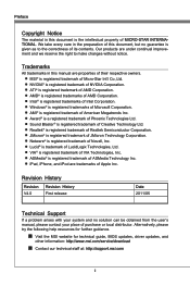
... Processing Unit 2-4 Memory 2-7 Power Supply 2-9 Back Panel 2-10 Connectors 2-12 Buttons 2-18 Voltage Check Point 2-19 LED Status Indicators 2-20 Jumper 2-21 Slots 2-22 Chapter 3 BIOS Setup 3-1 Entering Setup 3-2 The Main Menu 3-4 Green Power 3-5 Utilities 3-6 Overclocking 3-7 Games 3-14 Settings 3-15 viii
... Processing Unit 2-4 Memory 2-7 Power Supply 2-9 Back Panel 2-10 Connectors 2-12 Buttons 2-18 Voltage Check Point 2-19 LED Status Indicators 2-20 Jumper 2-21 Slots 2-22 Chapter 3 BIOS Setup 3-1 Entering Setup 3-2 The Main Menu 3-4 Green Power 3-5 Utilities 3-6 Overclocking 3-7 Games 3-14 Settings 3-15 viii
User Guide
Page 12
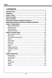
... /CoreTM i3/ Pentium®/ Celeron® processor in the LGA1155 package (For the latest information about CPU, please visit http://www.msi.com/service/cpu-support) Chipset ■ Intel® Z68 (B3) chipset Memory Support ■ 4 DDR3 DIMMs support DDR3 2133(... 1 mode by Marvell® SE9128 USB 3.0 ■ 2 USB 3.0 ports and 1 USB 3.0 onboard connector by NEC D720200 BIOS ■ Supports Dual BIOS (Z68A-GD65) ■ Supports Single BIOS (Z68A-GD55) Multi-GPU ■ Supports ATI® CrossFireX™ Technology ■ Supports NVIDIA® SLITM Technology ■ Supports Lucid&#...
... /CoreTM i3/ Pentium®/ Celeron® processor in the LGA1155 package (For the latest information about CPU, please visit http://www.msi.com/service/cpu-support) Chipset ■ Intel® Z68 (B3) chipset Memory Support ■ 4 DDR3 DIMMs support DDR3 2133(... 1 mode by Marvell® SE9128 USB 3.0 ■ 2 USB 3.0 ports and 1 USB 3.0 onboard connector by NEC D720200 BIOS ■ Supports Dual BIOS (Z68A-GD65) ■ Supports Single BIOS (Z68A-GD55) Multi-GPU ■ Supports ATI® CrossFireX™ Technology ■ Supports NVIDIA® SLITM Technology ■ Supports Lucid&#...

User Guide
Page 22
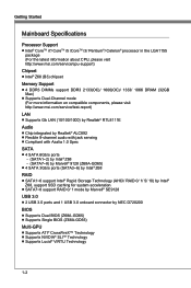
... over the mainboard to the CPU fan connector on the mainboard. Finally, attach the CPU Fan cable to confirm that the clip-ends are in BIOS. 2-6 Hardware Setup 5. Important • Confirm if your CPU socket pin with the cooler. Align the holes on your system. • Do not touch the CPU...
... over the mainboard to the CPU fan connector on the mainboard. Finally, attach the CPU Fan cable to confirm that the clip-ends are in BIOS. 2-6 Hardware Setup 5. Important • Confirm if your CPU socket pin with the cooler. Align the holes on your system. • Do not touch the CPU...

User Guide
Page 33
... front panel switches and LEDs. Chapter 2 1.C2.IGNTroRuUnd Front Panel Connectors: JFP1, JFP2 These connectors are for connecting the MSI future control card. 2.C4o.Cn6ot.rGn8otr.1lrCoo0puol1.inNnn2pdt1o.riC4noP.olCinnpotirnnotlropl in1p.i5n3V.C5So.BC7no.tCr9noo.tl1Grno1prtl.1roiCno3pulo.innGnpdtrirnooul npdin 2-17 The...mechanism will record this status and show a warning message on the screen. To clear the warning, you must enter the BIOS utility and clear the record. The JFP1 is reserved for electrical connection to the chassis intrusion switch cable. PowPoewr LeEr DSwi2tc...
... front panel switches and LEDs. Chapter 2 1.C2.IGNTroRuUnd Front Panel Connectors: JFP1, JFP2 These connectors are for connecting the MSI future control card. 2.C4o.Cn6ot.rGn8otr.1lrCoo0puol1.inNnn2pdt1o.riC4noP.olCinnpotirnnotlropl in1p.i5n3V.C5So.BC7no.tCr9noo.tl1Grno1prtl.1roiCno3pulo.innGnpdtrirnooul npdin 2-17 The...mechanism will record this status and show a warning message on the screen. To clear the warning, you must enter the BIOS utility and clear the record. The JFP1 is reserved for electrical connection to the chassis intrusion switch cable. PowPoewr LeEr DSwi2tc...
User Guide
Page 34
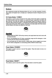
... values to change your mainboard's function through the use of button. And we suggest you to save the OC Genie configuration to overclocking profile in BIOS setup. Reset Button: RESET1 This button is in power off the system. Power Button: POWER1 This button is used to reset the system. 2-18 Important... OC Genie overclocking range and the damages or risks caused by the OC Genie overclocking behavior. • You can disable the OC Genie function in BIOS for you to turn-on or turn -off and unlock, and the system will light and lock. This section will off the system. Press the...
... values to change your mainboard's function through the use of button. And we suggest you to save the OC Genie configuration to overclocking profile in BIOS setup. Reset Button: RESET1 This button is in power off the system. Power Button: POWER1 This button is used to reset the system. 2-18 Important... OC Genie overclocking range and the damages or risks caused by the OC Genie overclocking behavior. • You can disable the OC Genie function in BIOS for you to turn-on or turn -off and unlock, and the system will light and lock. This section will off the system. Press the...

User Guide
Page 36
... Normal. Lights Off CPU is in 1 phase power mode. Follow the instructions below to read . Dual BIOS LED The Dual BIOS LED indicates the BIOS status during system power on. Solid: Both primary and secondary BIOS failed. 2-20 Follow the instructions below to read . CPU is in 2 phase power mode. CPU is ...in 6 phase power mode. Hardware Setup LED Status Indicators CPU Phase LEDs Dual BIOS LED CPU Phase LEDs These LEDs indicate the current CPU power phase mode. CPU is in 5 phase power mode. CPU is in 3 phase power ...
... Normal. Lights Off CPU is in 1 phase power mode. Follow the instructions below to read . Dual BIOS LED The Dual BIOS LED indicates the BIOS status during system power on. Solid: Both primary and secondary BIOS failed. 2-20 Follow the instructions below to read . CPU is in 2 phase power mode. CPU is ...in 6 phase power mode. Hardware Setup LED Status Indicators CPU Phase LEDs Dual BIOS LED CPU Phase LEDs These LEDs indicate the current CPU power phase mode. CPU is in 5 phase power mode. CPU is in 3 phase power ...
User Guide
Page 38
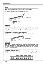
... Meanwhile, read the documentation for the expansion card to configure any necessary hardware or software settings for the expansion card, such as jumpers, switches or BIOS configuration. Hardware Setup Slots PCIE (Peripheral Component Interconnect Express) Slot The PCIE slot supports the PCIE interface expansion card. PCI Interrupt Request Routing The IRQ... the microprocessor. The PCI IRQ pins are hardware lines over which devices can send interrupt signals to the PCI bus pins as jumpers, switches or BIOS configuration.
... Meanwhile, read the documentation for the expansion card to configure any necessary hardware or software settings for the expansion card, such as jumpers, switches or BIOS configuration. Hardware Setup Slots PCIE (Peripheral Component Interconnect Express) Slot The PCIE slot supports the PCIE interface expansion card. PCI Interrupt Request Routing The IRQ... the microprocessor. The PCI IRQ pins are hardware lines over which devices can send interrupt signals to the PCI bus pins as jumpers, switches or BIOS configuration.

User Guide
Page 39
You may need to run the Setup program when: ■ An error message appears on the BIOS Setup program and allows you to run SETUP. ■ You want to configure the system for customized features. Chapter 3 BIOS Setup This chapter provides information on the screen during the system booting up, and requests you to change the default settings for optimum use.
You may need to run the Setup program when: ■ An error message appears on the BIOS Setup program and allows you to run SETUP. ■ You want to configure the system for customized features. Chapter 3 BIOS Setup This chapter provides information on the screen during the system booting up, and requests you to change the default settings for optimum use.

User Guide
Page 40
...as I = Intel, N = nVidia, A = AMD and V = VIA. 7th - 8th digit refers to the customer as MS = all standard customers. xxx refers to the BIOS version. 051211 refers to the date this chapter are under continuous update for reference only. • Upon boot-up, the 1st line appearing after the... memory count is usually in this BIOS was released. 3-2 You may be slightly different from the latest BIOS and should be held for better system performance. Therefore, the description may also restart the system by turning ...
...as I = Intel, N = nVidia, A = AMD and V = VIA. 7th - 8th digit refers to the customer as MS = all standard customers. xxx refers to the BIOS version. 051211 refers to the date this chapter are under continuous update for reference only. • Upon boot-up, the 1st line appearing after the... memory count is usually in this BIOS was released. 3-2 You may be slightly different from the latest BIOS and should be held for better system performance. Therefore, the description may also restart the system by turning ...

User Guide
Page 41
... press or double-click the left of certain fields that means a sub-menu can use and the possible selections for a field parameter. General Help The BIOS setup program provides a General Help screen. Press to the previous menu, just press the or click the right mouse button. Then you want to return...
... press or double-click the left of certain fields that means a sub-menu can use and the possible selections for a field parameter. General Help The BIOS setup program provides a General Help screen. Press to the previous menu, just press the or click the right mouse button. Then you want to return...

User Guide
Page 42
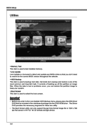
Use this menu to specify your settings for you to live update bios and hard disk backup. ▶ Overclocking Click "Overclocking" icon to enter the menu. This menu provides several games for frequency/voltage control and overclocking. ▶ ... "Utilities" icon to enter the menu. Use this menu to enter the menu. Please click it and select the language, at your desire, for the BIOS setting first. ▶ Green Power Click "Green Power" icon to specify your settings for you to play. ▶ Settings Click "Settings" icon to enter the...
Use this menu to specify your settings for you to live update bios and hard disk backup. ▶ Overclocking Click "Overclocking" icon to enter the menu. This menu provides several games for frequency/voltage control and overclocking. ▶ ... "Utilities" icon to enter the menu. Use this menu to enter the menu. Please click it and select the language, at your desire, for the BIOS setting first. ▶ Green Power Click "Green Power" icon to specify your settings for you to play. ▶ Settings Click "Settings" icon to enter the...
User Guide
Page 44
... up all the partition on image files. Important • Before you don't need to search for the correct BIOS version throughout the website. ▶ HDD Backup This item is used to select the boot screen. It consists ...necessary programs for these two utility. • The Boot Screen utility can restore the partition image to keep your BIOS online so that saved in the mainboard package into the DVD-ROM drive . When the data is lost or ... that you enter to the Live Update/ HDD Backup menu, please place the MSI Driver DVD that be included in FAT12/ 16/ 32 formats storage device. 3-6
... up all the partition on image files. Important • Before you don't need to search for the correct BIOS version throughout the website. ▶ HDD Backup This item is used to select the boot screen. It consists ...necessary programs for these two utility. • The Boot Screen utility can restore the partition image to keep your BIOS online so that saved in the mainboard package into the DVD-ROM drive . When the data is lost or ... that you enter to the Live Update/ HDD Backup menu, please place the MSI Driver DVD that be included in FAT12/ 16/ 32 formats storage device. 3-6
User Guide
Page 46
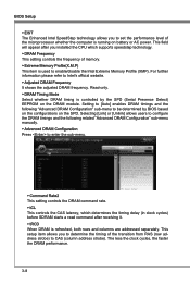
...item allows you to determine the timing of memory. ▶ Extreme Memory Profile(X.M.P) This item is running on battery or AC power. BIOS Setup ▶ EIST The Enhanced Intel SpeedStep technology allows you to set the performance level of the microprocessor whether the computer is used to...which determines the timing delay (in clock cycles) before SDRAM starts a read command after receiving it. ▶ tRCD When DRAM is controlled by BIOS based on the configurations on the DRAM module. Selecting [Link] or [Unlink] allows users to configure the DRAM timings and the following "Advanced ...
...item allows you to determine the timing of memory. ▶ Extreme Memory Profile(X.M.P) This item is running on battery or AC power. BIOS Setup ▶ EIST The Enhanced Intel SpeedStep technology allows you to set the performance level of the microprocessor whether the computer is used to...which determines the timing delay (in clock cycles) before SDRAM starts a read command after receiving it. ▶ tRCD When DRAM is controlled by BIOS based on the configurations on the DRAM module. Selecting [Link] or [Unlink] allows users to configure the DRAM timings and the following "Advanced ...
User Guide
Page 48
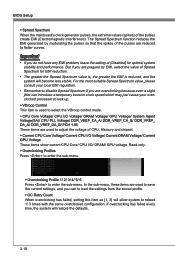
... clock speed which may just cause your local EMI regulation. • Remember to disable Spread Spectrum if you are reduced to enter the sub-menu. BIOS Setup ▶ Spread Spectrum When the mainboard's clock generator pulses, the extreme values (spikes) of CPU, Memory and chipset. ▶ Current CPU Core Voltage/ Current...
... clock speed which may just cause your local EMI regulation. • Remember to disable Spread Spectrum if you are reduced to enter the sub-menu. BIOS Setup ▶ Spread Spectrum When the mainboard's clock generator pulses, the extreme values (spikes) of CPU, Memory and chipset. ▶ Current CPU Core Voltage/ Current...
User Guide
Page 50
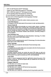
... prevent certain classes of malicious "buffer overflow" attacks when combined with HT Technology; • Chipset: An Intel® Chipset that supports HT Technology; • BIOS: A BIOS that supports HT Technology and has it cannot. When a malicious worm attempts to insert code in memory by where application code can monitor the current...execution, preventing damage or worm propagation. ▶ Intel Virtualization Tech This item is designed to limit the listed speed of the processor during idle. BIOS Setup • CPU: An Intel® Processor with a supporting operating system.
... prevent certain classes of malicious "buffer overflow" attacks when combined with HT Technology; • Chipset: An Intel® Chipset that supports HT Technology; • BIOS: A BIOS that supports HT Technology and has it cannot. When a malicious worm attempts to insert code in memory by where application code can monitor the current...execution, preventing damage or worm propagation. ▶ Intel Virtualization Tech This item is designed to limit the listed speed of the processor during idle. BIOS Setup • CPU: An Intel® Processor with a supporting operating system.

User Guide
Page 52
This DVD provides the necessary programs for you enter to play . Important Before you to play it and following the game rules to the Game menu, please place the MSI Driver DVD that be included in the mainboard package into the DVD-ROM drive . Simply click any icon to enter it . BIOS Setup Games This menu provides several games for the game utility. 3-14
This DVD provides the necessary programs for you enter to play . Important Before you to play it and following the game rules to the Game menu, please place the MSI Driver DVD that be included in the mainboard package into the DVD-ROM drive . Simply click any icon to enter it . BIOS Setup Games This menu provides several games for the game utility. 3-14

User Guide
Page 53
Settings MS-7681 Chapter 3 System Status ▶ System Date This allows you to set the system to Sat, determined by numeric function keys. date year The date from 1 to 31 can be keyed by BIOS. month The month from Sun to the date that you want (usually the current date). Read-only. The format is . day Day of the week, from Jan. through Dec. The year can be adjusted by users. 3-15
Settings MS-7681 Chapter 3 System Status ▶ System Date This allows you to set the system to Sat, determined by numeric function keys. date year The date from 1 to 31 can be keyed by BIOS. month The month from Sun to the date that you want (usually the current date). Read-only. The format is . day Day of the week, from Jan. through Dec. The year can be adjusted by users. 3-15
User Guide
Page 54
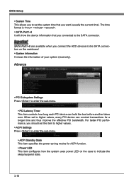
... mainboard. ▶ System Information It shows the information of your system (read only). Important SATA Port1~6 are available when you connected to the SATA connector. BIOS Setup ▶ System Time This allows you to set the system time that you connect the HDD devices to the SATA connectors on the case...
... mainboard. ▶ System Information It shows the information of your system (read only). Important SATA Port1~6 are available when you connected to the SATA connector. BIOS Setup ▶ System Time This allows you to set the system time that you connect the HDD devices to the SATA connectors on the case...

User Guide
Page 56
... Select an address and corresponding interrupt for Energy Using Products Lot 6 2013 (EuP) aka Energy Related Products (ErP). You can enable a fan target value here. BIOS Setup ▶ Onboard USB 3.0 Controller This item allows you to enable/ disable the USB 3.0 controller. ▶ USB3.0 Legacy Mode Support Select [Enabled] if you need...
... Select an address and corresponding interrupt for Energy Using Products Lot 6 2013 (EuP) aka Energy Related Products (ErP). You can enable a fan target value here. BIOS Setup ▶ Onboard USB 3.0 Controller This item allows you to enable/ disable the USB 3.0 controller. ▶ USB3.0 Legacy Mode Support Select [Enabled] if you need...


