User Guide
Page 2
... a problem arises with your system and no guarantee is given as to make changes without notice. Alternatively, please try the following help resources for further guidance. ◙ Visit the MSI website for technical guide, BIOS updates, driver updates, and other information: http://www.msi.com/service/download ◙ Contact our technical staff at: http://support.msi.com ii Trademarks All trademarks in this manual...
... a problem arises with your system and no guarantee is given as to make changes without notice. Alternatively, please try the following help resources for further guidance. ◙ Visit the MSI website for technical guide, BIOS updates, driver updates, and other information: http://www.msi.com/service/download ◙ Contact our technical staff at: http://support.msi.com ii Trademarks All trademarks in this manual...
User Guide
Page 8
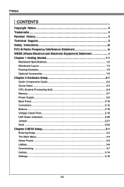
...(Waste Electrical and Electronic Equipment) Statement v Chapter 1 Getting Started 1-1 Mainboard Specifications 1-2 Mainboard Layout 1-4 Packing Contents 1-5 Optional Accessories 1-5 Chapter 2 Hardware Setup 2-1 Quick Components Guide 2-2 Screw Holes 2-3 CPU (Central Processing Unit 2-4 Memory 2-7 Power Supply 2-9 Back Panel 2-10 Connectors 2-12 Buttons 2-18 Voltage Check Point 2-19 LED Status Indicators 2-20 Jumper 2-21 Slots 2-22 Chapter 3 BIOS Setup 3-1 Entering Setup 3-2 The Main Menu 3-4 Green Power 3-5 Utilities 3-6 Overclocking 3-7 Games 3-14 Settings 3-15 viii
...(Waste Electrical and Electronic Equipment) Statement v Chapter 1 Getting Started 1-1 Mainboard Specifications 1-2 Mainboard Layout 1-4 Packing Contents 1-5 Optional Accessories 1-5 Chapter 2 Hardware Setup 2-1 Quick Components Guide 2-2 Screw Holes 2-3 CPU (Central Processing Unit 2-4 Memory 2-7 Power Supply 2-9 Back Panel 2-10 Connectors 2-12 Buttons 2-18 Voltage Check Point 2-19 LED Status Indicators 2-20 Jumper 2-21 Slots 2-22 Chapter 3 BIOS Setup 3-1 Entering Setup 3-2 The Main Menu 3-4 Green Power 3-5 Utilities 3-6 Overclocking 3-7 Games 3-14 Settings 3-15 viii
User Guide
Page 12
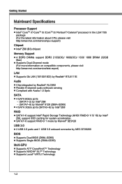
... 1.0 Spec SATA ■ 4 SATA 6Gb/s ports - (SATA1~2) by Intel® Z68 - (SATA7~8) by Marvell® 9128 (Z68A-GD65) ■ 4 SATA 3Gb/s ports (SATA3~6) by Intel® Z68 RAID ■ SATA1~6 support Intel® Rapid Storage Technology (AHCI/ RAID 0/ 1/ 5/ 10) by Intel® Z68, support SSD caching for system acceleration ■ SATA7~8 support RAID 0/ 1 mode by Marvell® SE9128 USB 3.0 ■ 2 USB 3.0 ports and 1 USB 3.0 onboard connector by NEC D720200 BIOS ■ Supports Dual BIOS (Z68A-GD65) ■ Supports Single BIOS (Z68A...
... 1.0 Spec SATA ■ 4 SATA 6Gb/s ports - (SATA1~2) by Intel® Z68 - (SATA7~8) by Marvell® 9128 (Z68A-GD65) ■ 4 SATA 3Gb/s ports (SATA3~6) by Intel® Z68 RAID ■ SATA1~6 support Intel® Rapid Storage Technology (AHCI/ RAID 0/ 1/ 5/ 10) by Intel® Z68, support SSD caching for system acceleration ■ SATA7~8 support RAID 0/ 1 mode by Marvell® SE9128 USB 3.0 ■ 2 USB 3.0 ports and 1 USB 3.0 onboard connector by NEC D720200 BIOS ■ Supports Dual BIOS (Z68A-GD65) ■ Supports Single BIOS (Z68A...
User Guide
Page 13
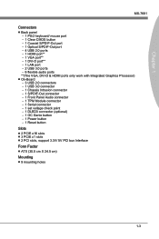
... port - 1 Clear CMOS button - 1 Coaxial S/PDIF-Out port - 1 Optical S/PDIF-Out port - 4 USB 2.0 ports - 1 HDMI port** - 1 VGA port** - 1 DVI-D port** - 1 LAN port - 2 USB 3.0 ports - 6 flexible audio ports **(The VGA, DVI-D & HDMI ports only work with Integrated Graphics Processor) ■ On-Board - 3 USB 2.0 connectors - 1 USB 3.0 connector - 1 Chassis Intrusion connector - 1 S/PDIF-Out connector - 1 Front Panel Audio connector - 1 TPM Module connector - 1 Serial connector - 1 set voltage check point - 1 DLED3 connector (optional) - 1 OC Genie button - 1 Power button - 1 Reset button Slots...
... port - 1 Clear CMOS button - 1 Coaxial S/PDIF-Out port - 1 Optical S/PDIF-Out port - 4 USB 2.0 ports - 1 HDMI port** - 1 VGA port** - 1 DVI-D port** - 1 LAN port - 2 USB 3.0 ports - 6 flexible audio ports **(The VGA, DVI-D & HDMI ports only work with Integrated Graphics Processor) ■ On-Board - 3 USB 2.0 connectors - 1 USB 3.0 connector - 1 Chassis Intrusion connector - 1 S/PDIF-Out connector - 1 Front Panel Audio connector - 1 TPM Module connector - 1 Serial connector - 1 set voltage check point - 1 DLED3 connector (optional) - 1 OC Genie button - 1 Power button - 1 Reset button Slots...
User Guide
Page 27
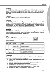
..., is properly connected to your monitor (refer to Yellow the Local Area Network (LAN). To connect an LCD monitor, simply plug your monitor manual for connection to your monitor cable into the DVI-D connector, and make sure that the other audio devices. ■ Line-Out: Green - LAN link is provided for monitor. ▶ DVI-D Port The DVI-D (Digital Visual Interface-Digital) connector allows you installed a processor without integrated graphics chip, these display ports will have...
..., is properly connected to your monitor (refer to Yellow the Local Area Network (LAN). To connect an LCD monitor, simply plug your monitor manual for connection to your monitor cable into the DVI-D connector, and make sure that the other audio devices. ■ Line-Out: Green - LAN link is provided for monitor. ▶ DVI-D Port The DVI-D (Digital Visual Interface-Digital) connector allows you installed a processor without integrated graphics chip, these display ports will have...
User Guide
Page 29
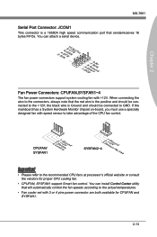
... processor's official website or consult the vendors for CPUFAN and SYSFAN1. 2-13 If the mainboard has a System Hardware Monitor chipset on-board, you must use a specially designed fan with +12V. You can attach a serial device. 2.S4I.ND6T.DR8S1.C0RT.NSo Pin 1.D3.CS5DO.G7Ur.RTo9uT.RnSdI Fan Power Connectors: CPUFAN,SYSFAN1~4 The fan power connectors support system cooling fan with speed sensor to take advantage of the CPU fan control. When connecting the wire...
... processor's official website or consult the vendors for CPUFAN and SYSFAN1. 2-13 If the mainboard has a System Hardware Monitor chipset on-board, you must use a specially designed fan with +12V. You can attach a serial device. 2.S4I.ND6T.DR8S1.C0RT.NSo Pin 1.D3.CS5DO.G7Ur.RTo9uT.RnSdI Fan Power Connectors: CPUFAN,SYSFAN1~4 The fan power connectors support system cooling fan with speed sensor to take advantage of the CPU fan control. When connecting the wire...
User Guide
Page 30
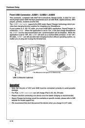
... will work as USB HDD, digital cameras, MP3 players, printers, modems and the like. USB 2.0 Bracket (optional) Important • Note that connecting one device once for connecting high-speed USB interface peripherals such as a normal USB connector. When the application is recommended. • Super-Charger technology would be available on specific models, please refer to control the JUSB1 . When the application is ideal for stable charging is set...
... will work as USB HDD, digital cameras, MP3 players, printers, modems and the like. USB 2.0 Bracket (optional) Important • Note that connecting one device once for connecting high-speed USB interface peripherals such as a normal USB connector. When the application is recommended. • Super-Charger technology would be available on specific models, please refer to control the JUSB1 . When the application is ideal for stable charging is set...
User Guide
Page 34
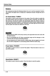
... the button again after booting the system. Power Button: POWER1 This button is used to change your mainboard's function through the use of button. Press the button to auto-overclock for next boot. OC Genie Button: TURBO1 This button is used to turn-on or turn -off and unlock, and the system will light and lock. Reset Button: RESET1 This button is in BIOS setup. Press the button to set the computer's function. Press this button to enable the...
... the button again after booting the system. Power Button: POWER1 This button is used to change your mainboard's function through the use of button. Press the button to auto-overclock for next boot. OC Genie Button: TURBO1 This button is used to turn-on or turn -off and unlock, and the system will light and lock. Reset Button: RESET1 This button is in BIOS setup. Press the button to set the computer's function. Press this button to enable the...
User Guide
Page 38
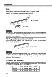
... as jumpers, switches or BIOS configuration. PCI (Peripheral Component Interconnect) Slot The PCI slot supports LAN card, SCSI card, USB card, and other add-on cards that comply with PCI specifications. 32-bit PCI Slot Important When adding or removing expansion cards, make sure that you unplug the power supply first. The PCI IRQ pins are hardware lines over which devices can send interrupt signals to configure any necessary hardware or software settings for the expansion card to the PCI bus pins as jumpers, switches or BIOS configuration. PCI...
... as jumpers, switches or BIOS configuration. PCI (Peripheral Component Interconnect) Slot The PCI slot supports LAN card, SCSI card, USB card, and other add-on cards that comply with PCI specifications. 32-bit PCI Slot Important When adding or removing expansion cards, make sure that you unplug the power supply first. The PCI IRQ pins are hardware lines over which devices can send interrupt signals to configure any necessary hardware or software settings for the expansion card to the PCI bus pins as jumpers, switches or BIOS configuration. PCI...
User Guide
Page 48
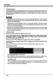
... disable Spread Spectrum if you are used to load the settings from the stored profile. ▶ OC Retry Count When overclocking has failed, setting this item as [1, 3] will restore the defaults. 3-10 BIOS Setup ▶ Spread Spectrum When the mainboard's clock generator pulses, the extreme values (spikes) of CPU, Memory and chipset. ▶ Current CPU Core Voltage/ Current CPU I/O Voltage/ Current DRAM Voltage/ Current GPU Voltage These items show current CPU Core/ CPU I/O/ DRAM/ GPU voltage. If overclocking...
... disable Spread Spectrum if you are used to load the settings from the stored profile. ▶ OC Retry Count When overclocking has failed, setting this item as [1, 3] will restore the defaults. 3-10 BIOS Setup ▶ Spread Spectrum When the mainboard's clock generator pulses, the extreme values (spikes) of CPU, Memory and chipset. ▶ Current CPU Core Voltage/ Current CPU I/O Voltage/ Current DRAM Voltage/ Current GPU Voltage These items show current CPU Core/ CPU I/O/ DRAM/ GPU voltage. If overclocking...
User Guide
Page 54
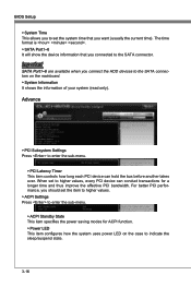
... effective PCI bandwidth. For better PCI performance, you connected to indicate the sleep/suspend state. 3-16 The time format is . ▶ SATA Port1~6 It will show the device information that you connect the HDD devices to enter the sub-menu. ▶ PCI Latency Timer This item controls how long each PCI device can conduct transactions for ACPI function. ▶ Power LED This item configures how the system uses power LED on the mainboard. ▶...
... effective PCI bandwidth. For better PCI performance, you connected to indicate the sleep/suspend state. 3-16 The time format is . ▶ SATA Port1~6 It will show the device information that you connect the HDD devices to enter the sub-menu. ▶ PCI Latency Timer This item controls how long each PCI device can conduct transactions for ACPI function. ▶ Power LED This item configures how the system uses power LED on the mainboard. ▶...
User Guide
Page 57
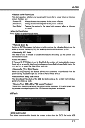
... used to enable or disable the feature of the PS/2 mouse/ keyboard is set to [Enabled], the system will automatically resume (boot up) on a specific date/hour/minute/second specified in the power on state. [Last State] Restore the system to the status before power failure or interrupt occurred. ▶ Wake Up Event Setup Press to enter the sub-menu. ▶ Wake Up Event By Setting to [BIOS...
... used to enable or disable the feature of the PS/2 mouse/ keyboard is set to [Enabled], the system will automatically resume (boot up) on a specific date/hour/minute/second specified in the power on state. [Last State] Restore the system to the status before power failure or interrupt occurred. ▶ Wake Up Event Setup Press to enter the sub-menu. ▶ Wake Up Event By Setting to [BIOS...
User Guide
Page 58
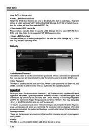
... system will replace any password. The password typed now will boot from selected UEFI file. ▶ Save current UEFI rom to file Please setup a specific folder in specific USB/ Storage drive to set password from CMOS memory. This item allows to select particular UEFI file from the USB/ Storage (FAT/ 32 format only) drive for updating BIOS. Once the password is used to save UEFI file from ROM chip data. BIOS Setup drive (FAT/ 32 format only). ▶ Select UEFI file to boot from When the BIOS Boot function as a key. 3-20...
... system will replace any password. The password typed now will boot from selected UEFI file. ▶ Save current UEFI rom to file Please setup a specific folder in specific USB/ Storage drive to set password from CMOS memory. This item allows to select particular UEFI file from the USB/ Storage (FAT/ 32 format only) drive for updating BIOS. Once the password is used to save UEFI file from ROM chip data. BIOS Setup drive (FAT/ 32 format only). ▶ Select UEFI file to boot from When the BIOS Boot function as a key. 3-20...
User Guide
Page 59
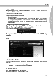
... sets to [Enabled], this system to reflash the primary BIOS for Z68A-GD65 only) When "Enabled", and the primary BIOS has failed, the system will show the company logo on the full screen at boot. [Disabled] Shows the POST messages at When the "U-Key" as below. Multi BIOS auto update starting. This item allows you to specify the USB driver device. ▶ Chassis Intrusion Configuration Press to enter the sub-menu. ▶ Chassis...
... sets to [Enabled], this system to reflash the primary BIOS for Z68A-GD65 only) When "Enabled", and the primary BIOS has failed, the system will show the company logo on the full screen at boot. [Disabled] Shows the POST messages at When the "U-Key" as below. Multi BIOS auto update starting. This item allows you to specify the USB driver device. ▶ Chassis Intrusion Configuration Press to enter the sub-menu. ▶ Chassis...
User Guide
Page 70
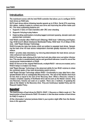
... 6 Gb/s. Spreading the hard drive I/O load across independent channels greatly improves I/O performance. This results in your PC. The size of hard drives for RAID 0, RAID 1, Recovery or Matrix mode is 4. They are : 1. The least number of the Master drive must be used in this appendix. Serial ATA uses long, thin cables, making it easier to the Recovery drive. Supports Hot-plug-n-play feature. 3. Intel® RAID controller offers RAID level 0 (Striping), RAID level 1 (Mirroring and...
... 6 Gb/s. Spreading the hard drive I/O load across independent channels greatly improves I/O performance. This results in your PC. The size of hard drives for RAID 0, RAID 1, Recovery or Matrix mode is 4. They are : 1. The least number of the Master drive must be used in this appendix. Serial ATA uses long, thin cables, making it easier to the Recovery drive. Supports Hot-plug-n-play feature. 3. Intel® RAID controller offers RAID level 0 (Striping), RAID level 1 (Mirroring and...
User Guide
Page 71
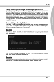
... for Serial ATA" status screen, which should appear early in system boot-up, during the POST (PowerOn Self Test). Appendix B MS-7681 Using Intel Rapid Storage Technology Option ROM The Intel Rapid Storage Technology Option ROM should be integrated with the system BIOS on all mainboards with a newly-built system or if you need to enable the RAID function in BIOS to create, delete and reset RAID volumes. Please use + keys to enter...
... for Serial ATA" status screen, which should appear early in system boot-up, during the POST (PowerOn Self Test). Appendix B MS-7681 Using Intel Rapid Storage Technology Option ROM The Intel Rapid Storage Technology Option ROM should be integrated with the system BIOS on all mainboards with a newly-built system or if you need to enable the RAID function in BIOS to create, delete and reset RAID volumes. Please use + keys to enter...
User Guide
Page 78
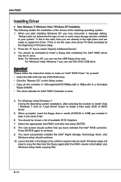
... MSI DVD into the A: drive. Select the appropriate Intel RAID controller and press ENTER. 8. You have selected the Intel® RAID controller. The next screen should confirm that you can use CD/ DVD/ USB drive. Intel RAID Installing Driver ■ New Windows 7/ Windows Vista / Windows XP Installation The following details the installation of Windows setup. 2. You should be shown a list of one or more mass storage devices installed in the right place and are ready to a formatted floppy...
... MSI DVD into the A: drive. Select the appropriate Intel RAID controller and press ENTER. 8. You have selected the Intel® RAID controller. The next screen should confirm that you can use CD/ DVD/ USB drive. Intel RAID Installing Driver ■ New Windows 7/ Windows Vista / Windows XP Installation The following details the installation of Windows setup. 2. You should be shown a list of one or more mass storage devices installed in the right place and are ready to a formatted floppy...
User Guide
Page 79
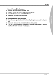
B-11 The driver Intel(R) SATA RAID Controller should appear. From Windows, open the Control Panel from My Computer followed by the System icon. 2. Insert the MSI DVD into the DVD-ROM drive. 2. The drivers will appear. 3. Click the "+" in front of the SCSI and RAID Controllers hardware type. Appendix B MS-7681 ■ Existing Windows Driver Installation 1. The DVD will auto-run and the setup screen will be automatically installed. ■ Confirming Windows Driver Installation 1. Under the Driver tab, click...
B-11 The driver Intel(R) SATA RAID Controller should appear. From Windows, open the Control Panel from My Computer followed by the System icon. 2. Insert the MSI DVD into the DVD-ROM drive. 2. The drivers will appear. 3. Click the "+" in front of the SCSI and RAID Controllers hardware type. Appendix B MS-7681 ■ Existing Windows Driver Installation 1. The DVD will auto-run and the setup screen will be automatically installed. ■ Confirming Windows Driver Installation 1. Under the Driver tab, click...
User Guide
Page 82
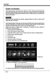
... Intel® Rapid Storage Technology use a slow virtual disk or depend on the Setup screen. Follow these steps to Windows. 8. Install Intel® RAID controller driver. Install Windows operating system. 5. Connect the SSD. 7. Insert the MSI DVD into the DVD-ROM drive. 9. Click here 10. Even though there is only one hard drive, you must be installed in the RAID ready disk in order to use the SSD caching. If Windows has been installed in order to accelerate...
... Intel® Rapid Storage Technology use a slow virtual disk or depend on the Setup screen. Follow these steps to Windows. 8. Install Intel® RAID controller driver. Install Windows operating system. 5. Connect the SSD. 7. Insert the MSI DVD into the DVD-ROM drive. 9. Click here 10. Even though there is only one hard drive, you must be installed in the RAID ready disk in order to use the SSD caching. If Windows has been installed in order to accelerate...
User Guide
Page 84
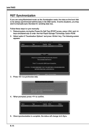
... key. Previous Menu [ SYNCHRONIZATION VERIFICATION ] SYNCHRONIZING THE DA5T. When prompted, press to enter the Intel Rapid Storage Technology Option ROM. 2. Select 3. D[O DNIOSTK I/NVTOELRURMUEPINTFTOHREMPARTOIOCNES]S! Reboot system, during the Power-On Self Test (POST) press, press and keys simultaneously to confirm. The following screen appears. Name DISK PORT 0 [ ACCELERATION OPTIONS ] Type Non-RAID Disk Capacity Mode 153.4GB Maximized Status In Sync 5. Press 'r' to the Accelerated Disk/Volume. Name DISK PORT 0 [ ACCELERATION OPTIONS ] Type Non-RAID Disk...
... key. Previous Menu [ SYNCHRONIZATION VERIFICATION ] SYNCHRONIZING THE DA5T. When prompted, press to enter the Intel Rapid Storage Technology Option ROM. 2. Select 3. D[O DNIOSTK I/NVTOELRURMUEPINTFTOHREMPARTOIOCNES]S! Reboot system, during the Power-On Self Test (POST) press, press and keys simultaneously to confirm. The following screen appears. Name DISK PORT 0 [ ACCELERATION OPTIONS ] Type Non-RAID Disk Capacity Mode 153.4GB Maximized Status In Sync 5. Press 'r' to the Accelerated Disk/Volume. Name DISK PORT 0 [ ACCELERATION OPTIONS ] Type Non-RAID Disk...


