User Guide
Page 3
.../220V before connecting the equipment to User's Manual. ◯ The equipment has been dropped and damaged. ◯ The equipment has obvious sign of the following help resources for further guidance. ◙ Visit the MSI website for technical guide, BIOS updates, driver updates, and other information: http://www.msi.com/service/download ◙ Contact our technical staff at: http://support.msi.com Safety Instructions ■ Always...
.../220V before connecting the equipment to User's Manual. ◯ The equipment has been dropped and damaged. ◯ The equipment has obvious sign of the following help resources for further guidance. ◙ Visit the MSI website for technical guide, BIOS updates, driver updates, and other information: http://www.msi.com/service/download ◙ Contact our technical staff at: http://support.msi.com Safety Instructions ■ Always...

User Guide
Page 9
... and Electronic Equipment) Statement vi Chapter 1 Getting Started 1-1 Packing Contents 1-2 Optional Accessories 1-2 Assembly Precautions 1-3 Mainboard Specifications 1-4 Connectors Quick Guide 1-6 Back Panel Quick Guide 1-8 CPU (Central Processing Unit 1-10 Mounting Screw Holes 1-14 Power Supply 1-15 Memory 1-16 Expansion Slots 1-20 Video/ Graphics Cards 1-21 Internal Connectors 1-26 Buttons 1-34 Jumpers 1-36 Switch 1-37 LED Status Indicators 1-38 Chapter 2 BIOS Setup 2-1 Entering 2-2 Overview 2-2 Boot device priority bar 2-3 Operation 2-4 SETTINGS 2-5 OC 2-10 ix
... and Electronic Equipment) Statement vi Chapter 1 Getting Started 1-1 Packing Contents 1-2 Optional Accessories 1-2 Assembly Precautions 1-3 Mainboard Specifications 1-4 Connectors Quick Guide 1-6 Back Panel Quick Guide 1-8 CPU (Central Processing Unit 1-10 Mounting Screw Holes 1-14 Power Supply 1-15 Memory 1-16 Expansion Slots 1-20 Video/ Graphics Cards 1-21 Internal Connectors 1-26 Buttons 1-34 Jumpers 1-36 Switch 1-37 LED Status Indicators 1-38 Chapter 2 BIOS Setup 2-1 Entering 2-2 Overview 2-2 Boot device priority bar 2-3 Operation 2-4 SETTINGS 2-5 OC 2-10 ix

User Guide
Page 14
... Started Mainboard Specifications Processor Support ■ 2nd Generation Intel® Core™ i7 Processors in an LGA 2011 socket (For the latest information about CPU, please visit http://www.msi.com/service/cpu-support) Chipset ■ Intel® X79 chipset Memory Support ■ 8x DDR3 DIMMs support DDR3 2400*(OC)/ 2133*(OC)/ 1800*(OC)/ 1600/ 1333/ 1066 DRAM (128GB Max) ■ Supports Quad-Channel mode, two DIMMs per channel (*OC = OverClocking, for more information on compatible...
... Started Mainboard Specifications Processor Support ■ 2nd Generation Intel® Core™ i7 Processors in an LGA 2011 socket (For the latest information about CPU, please visit http://www.msi.com/service/cpu-support) Chipset ■ Intel® X79 chipset Memory Support ■ 8x DDR3 DIMMs support DDR3 2400*(OC)/ 2133*(OC)/ 1800*(OC)/ 1600/ 1333/ 1066 DRAM (128GB Max) ■ Supports Quad-Channel mode, two DIMMs per channel (*OC = OverClocking, for more information on compatible...

User Guide
Page 17
... Guide Port Type LGA2011 CPU Socket ATX 24-pin Power Connector ATX 8-pin Power Connector ATX 4-pin Power Connector DDR3 Memory Slots PCIe 3.0 x16 Expansion Slots PCIe 2.0 x16 Expansion Slots PCIe 2.0 x1 Expansion Slots SATA 6Gb/s Connectors SATA 3Gb/s Connectors CPU Fan Power Connector System Fan Power Connectors Front Panel Connectors USB 2.0 Expansion Connectors USB 3.0 Expansion Connector IEEE1394 Expansion Connector Chassis Intrusion Connector Front Panel Audio Connector Voice Genie Connector MultiConnect Panel Connector OC Genie Button Power Button Direct OC Buttons Clear CMOS Jumper...
... Guide Port Type LGA2011 CPU Socket ATX 24-pin Power Connector ATX 8-pin Power Connector ATX 4-pin Power Connector DDR3 Memory Slots PCIe 3.0 x16 Expansion Slots PCIe 2.0 x16 Expansion Slots PCIe 2.0 x1 Expansion Slots SATA 6Gb/s Connectors SATA 3Gb/s Connectors CPU Fan Power Connector System Fan Power Connectors Front Panel Connectors USB 2.0 Expansion Connectors USB 3.0 Expansion Connector IEEE1394 Expansion Connector Chassis Intrusion Connector Front Panel Audio Connector Voice Genie Connector MultiConnect Panel Connector OC Genie Button Power Button Direct OC Buttons Clear CMOS Jumper...

User Guide
Page 25
....+3dV2.5+4V5.GVround BATT + ATX 8-pin Power Connector: JPWR2 This connector provides 12V power to the CPU. 1.G2.rG3o.urG4on.urdGonurdonudnd 5.+61.+721.V+821.V+21V2V BATT + ATX 4-pin Power Connector: JPWR3 This connector is used to provide power to connect an ATX 24-pin power supply. BATT + 4.+31.G22.rVG1o.ur+on5udVnd Important Make sure that all the power cables are securely connected to a proper ATX power supply to ensure stable operation of the mainboard. 1-15
....+3dV2.5+4V5.GVround BATT + ATX 8-pin Power Connector: JPWR2 This connector provides 12V power to the CPU. 1.G2.rG3o.urG4on.urdGonurdonudnd 5.+61.+721.V+821.V+21V2V BATT + ATX 4-pin Power Connector: JPWR3 This connector is used to provide power to connect an ATX 24-pin power supply. BATT + 4.+31.G22.rVG1o.ur+on5udVnd Important Make sure that all the power cables are securely connected to a proper ATX power supply to ensure stable operation of the mainboard. 1-15

User Guide
Page 30
... removing expansion cards, always turn off the power supply and unplug the power supply power cable from the power outlet. Symbol ●: Install graphics cards in to check for expansion cards, such as discrete graphics or audio cards. Read the expansion card's documentation to the PCIe slots. Graphics Card Installation Table The following table shows the graphics cards installation rules. Getting Started Expansion Slots This mainboard contains numerous ports for any necessary additional hardware or software changes. Symbol ◎: Connect the monitor to the graphic card. PCIe...
... removing expansion cards, always turn off the power supply and unplug the power supply power cable from the power outlet. Symbol ●: Install graphics cards in to check for expansion cards, such as discrete graphics or audio cards. Read the expansion card's documentation to the PCIe slots. Graphics Card Installation Table The following table shows the graphics cards installation rules. Getting Started Expansion Slots This mainboard contains numerous ports for any necessary additional hardware or software changes. Symbol ◎: Connect the monitor to the graphic card. PCIe...
User Guide
Page 34
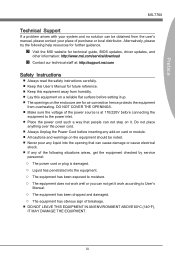
... graphics cards in the PCI_E1 & PCI_E4 slots. 2. Attach one side of the cable on the graphics card installed in the first PCIe x16 slot will work. SLI Video Link Card 3. To utilize this technology, the GPU cards must be connected to properly set up the computer and install the drivers and software included in your video card. 1-24 The instructions below to this graphics card. Please note that came with your video card package. Getting Started NVIDIA® SLI Technology NVIDIA's SLI...
... graphics cards in the PCI_E1 & PCI_E4 slots. 2. Attach one side of the cable on the graphics card installed in the first PCIe x16 slot will work. SLI Video Link Card 3. To utilize this technology, the GPU cards must be connected to properly set up the computer and install the drivers and software included in your video card. 1-24 The instructions below to this graphics card. Please note that came with your video card package. Getting Started NVIDIA® SLI Technology NVIDIA's SLI...

User Guide
Page 44
... to enable OC Genie. OC Genie Button: OC Genie This button is at the user's own risk. Please refer to the BIOS section of the manual for instructions on how to turn off the system and press the OC Genie button again. BATT + Getting Started Buttons The mainboard has numerous on -board buttons. This section will return to automatically overclock the system. On the next boot...
... to enable OC Genie. OC Genie Button: OC Genie This button is at the user's own risk. Please refer to the BIOS section of the manual for instructions on how to turn off the system and press the OC Genie button again. BATT + Getting Started Buttons The mainboard has numerous on -board buttons. This section will return to automatically overclock the system. On the next boot...

User Guide
Page 46
... the mainboard. Disabled Enabled BATT + Important Users will vary according to boot at their own risks. Low Temperature Booting Jumpers: JCOLD1, JCOLD2 These jumpers are used for liquid nitrogen cooling system to the CPU version. 1-36 Afterwards, open the jumper . If you want to clear the system configuration, set one or both jumpers to Enabled to save system configuration data. Do not clear the CMOS RAM while the system is off. The overclocking...
... the mainboard. Disabled Enabled BATT + Important Users will vary according to boot at their own risks. Low Temperature Booting Jumpers: JCOLD1, JCOLD2 These jumpers are used for liquid nitrogen cooling system to the CPU version. 1-36 Afterwards, open the jumper . If you want to clear the system configuration, set one or both jumpers to Enabled to save system configuration data. Do not clear the CMOS RAM while the system is off. The overclocking...
User Guide
Page 56
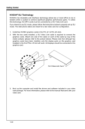
...; ACPI Settings Press to enter the sub-menu. ▶ ACPI Standby State Specifies the power saving mode for SATA port. BIOS Setup Advanced ▶ PCI Subsystem Settings Press to specify RAID/ IDE/ AHCI mode for ACPI function [S1] Sleep Mode. Hardware remains on the case to indicate sleep/ suspend state. [Single] The power LED turns off hardware. (Recommended) ▶ Power LED Configures how the system uses power LEDs on . [S3] Suspend to enable/ disable the HD audio controller. 2-6 If you have your BIOS/reset to default settings, you to RAM...
...; ACPI Settings Press to enter the sub-menu. ▶ ACPI Standby State Specifies the power saving mode for SATA port. BIOS Setup Advanced ▶ PCI Subsystem Settings Press to specify RAID/ IDE/ AHCI mode for ACPI function [S1] Sleep Mode. Hardware remains on the case to indicate sleep/ suspend state. [Single] The power LED turns off hardware. (Recommended) ▶ Power LED Configures how the system uses power LEDs on . [S3] Suspend to enable/ disable the HD audio controller. 2-6 If you have your BIOS/reset to default settings, you to RAM...

User Guide
Page 57
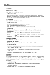
... is part of the chipset. Note: When enabled, the system will not support RTC wake up event functions. ▶ Restore after a power failure or interrupt occurs. Chapter 2 MS-7760 ▶ HPET The HPET (High Precision Event Timers) is a component that do not support USB. ▶ Onboard USB 3.0 Controller This item allows you to enable/ disable the USB 3.0 controller. ▶ Hardware Monitor Press to enter the sub-menu. ▶ CPU Smart Fan Target Controls CPU fan speed automatically...
... is part of the chipset. Note: When enabled, the system will not support RTC wake up event functions. ▶ Restore after a power failure or interrupt occurs. Chapter 2 MS-7760 ▶ HPET The HPET (High Precision Event Timers) is a component that do not support USB. ▶ Onboard USB 3.0 Controller This item allows you to enable/ disable the USB 3.0 controller. ▶ Hardware Monitor Press to enter the sub-menu. ▶ CPU Smart Fan Target Controls CPU fan speed automatically...

User Guide
Page 58
... what power saving modes when input signal of the USB device to wake up events. Save & Exit ▶ Discard Changes and Exit Use this item to abandon all changes and exit setup. ▶ Save Changes and Reset Use this item to save changes and reset the system. ▶ Save Changes Use this item to prioritize the installed CD/DVD ROM/ USB key drives/ UEFI boot drives. Setting to [OS], the wake up events will be defined by USB Device...
... what power saving modes when input signal of the USB device to wake up events. Save & Exit ▶ Discard Changes and Exit Use this item to abandon all changes and exit setup. ▶ Save Changes and Reset Use this item to save changes and reset the system. ▶ Save Changes Use this item to prioritize the installed CD/DVD ROM/ USB key drives/ UEFI boot drives. Setting to [OS], the wake up events will be defined by USB Device...
User Guide
Page 61
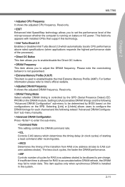
... that support this technology. ▶ Intel Turbo Boost 2.0 Enables or disables Intel Turbo Boost 2.0 which determines the timing delay (in the system. 2-11 Read-only. ▶ DRAM Timing Mode Select whether DRAM timing is controlled by BIOS based on the configurations on the DRAM module. This item applies only when synchronous DRAM is used to enable/disable the Intel Extreme Memory Profile (XMP). Please note the overclocking...
... that support this technology. ▶ Intel Turbo Boost 2.0 Enables or disables Intel Turbo Boost 2.0 which determines the timing delay (in the system. 2-11 Read-only. ▶ DRAM Timing Mode Select whether DRAM timing is controlled by BIOS based on the configurations on the DRAM module. This item applies only when synchronous DRAM is used to enable/disable the Intel Extreme Memory Profile (XMP). Please note the overclocking...

User Guide
Page 64
... restore the defaults. ▶ CPU Specifications Press to enter the sub-menu. The information will vary by pressing [F5]. Press to enter the sub-menu. ▶ CPU Technology Support Press to enter the sub-menu. In this way, the system performance is designed to limit the listed speed of the processor to older operating systems. ▶ Execute Disable Bit Can prevent certain classes of installed memory. ▶ CPU Features Press...
... restore the defaults. ▶ CPU Specifications Press to enter the sub-menu. The information will vary by pressing [F5]. Press to enter the sub-menu. ▶ CPU Technology Support Press to enter the sub-menu. In this way, the system performance is designed to limit the listed speed of the processor to older operating systems. ▶ Execute Disable Bit Can prevent certain classes of installed memory. ▶ CPU Features Press...

User Guide
Page 69
... update BIOS This item allows you to save BIOS file from BIOS ROM chip data. Note: it only supports FAT/ 32 file system drive. ▶ Select one file to Boot When the BIOS Boot function as sets to select particular BIOS file from the USB/ Storage (FAT/ 32 format only) drive for updating BIOS. 2-19 And the system will boot from selected BIOS file. ▶ Save BIOS to storage Please setup a specific folder in specific USB/ Storage drive to select a particular BIOS file from the USB/ Storage...
... update BIOS This item allows you to save BIOS file from BIOS ROM chip data. Note: it only supports FAT/ 32 file system drive. ▶ Select one file to Boot When the BIOS Boot function as sets to select particular BIOS file from the USB/ Storage (FAT/ 32 format only) drive for updating BIOS. 2-19 And the system will boot from selected BIOS file. ▶ Save BIOS to storage Please setup a specific folder in specific USB/ Storage drive to select a particular BIOS file from the USB/ Storage...
User Guide
Page 70
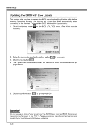
... correct version and model of BIOS and download the appropriate file. 5. Important Do not unplug or shut off your motherboard BIOS when updating. 2-20 Please ensure you how to the Internet. Setup the connection by using the Live Update utility before entering Operating System. Click the next button . 4. Live Update will automatically detect the version of your system during BIOS Flash. Click the confirm button to not POST. on the BIOS UTILITIES menu. (The...
... correct version and model of BIOS and download the appropriate file. 5. Important Do not unplug or shut off your motherboard BIOS when updating. 2-20 Please ensure you how to the Internet. Setup the connection by using the Live Update utility before entering Operating System. Click the next button . 4. Live Update will automatically detect the version of your system during BIOS Flash. Click the confirm button to not POST. on the BIOS UTILITIES menu. (The...

User Guide
Page 71
.... ▶ U-Key Enable or disable USB driver device as key. This item allows you are prompted to enter a new password. Type the password then press . The setting of recording the chassis intrusion status and issuing a warning message if opened. SECURITY MS-7760 Chapter 2 ▶ Administrator Password Set the administrative password that will be required to enter the BIOS. ▶ User Password Set the user password that will replace any previous set password from CMOS memory. Once the password is...
.... ▶ U-Key Enable or disable USB driver device as key. This item allows you are prompted to enter a new password. Type the password then press . The setting of recording the chassis intrusion status and issuing a warning message if opened. SECURITY MS-7760 Chapter 2 ▶ Administrator Password Set the administrative password that will be required to enter the BIOS. ▶ User Password Set the user password that will replace any previous set password from CMOS memory. Once the password is...
User Guide
Page 81
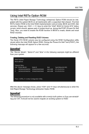
...-RAID Disk Non-RAID Disk Press to RAID. It should not be different from your OS. Please use + keys to enter the Intel Rapid Storage Technology enterprise Option ROM. B-3 The Intel RSTe Option ROM is only available with a supported Intel chipset. Creating, Deleting and Resetting RAID Volumes: The Serial ATA RAID volume may be integrated with the system BIOS on all mainboards with a newly-built system or if you need to enable the RAID...
...-RAID Disk Non-RAID Disk Press to RAID. It should not be different from your OS. Please use + keys to enter the Intel Rapid Storage Technology enterprise Option ROM. B-3 The Intel RSTe Option ROM is only available with a supported Intel chipset. Creating, Deleting and Resetting RAID Volumes: The Serial ATA RAID volume may be integrated with the system BIOS on all mainboards with a newly-built system or if you need to enable the RAID...
User Guide
Page 87
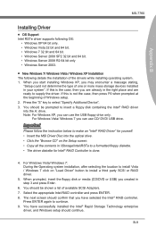
...; RAID Controller is the case, then you may encounter a message stating, "Setup could not determine the type of available SCSI Adapters. 7. You should be shown a list of one or more mass storage devices installed in step 3 and press Enter. 6. Press ENTER again to a formatted floppy diskette. • The driver diskette for yourself. • Insert the MSI Driver Disc into the A: drive. For Windows Vista/ Windows 7 you can use the USB floppy drive...
...; RAID Controller is the case, then you may encounter a message stating, "Setup could not determine the type of available SCSI Adapters. 7. You should be shown a list of one or more mass storage devices installed in step 3 and press Enter. 6. Press ENTER again to a formatted floppy diskette. • The driver diskette for yourself. • Insert the MSI Driver Disc into the A: drive. For Windows Vista/ Windows 7 you can use the USB floppy drive...
User Guide
Page 88
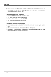
Insert the MSI Driver Disc into the optical drive. 2. The setup screen will be automatically installed. ■ Confirming Windows Driver Installation 1. The driver Intel(R) SATA RAID Controller should appear. Under the Driver tab, click on Intel RAID Drivers. 4. From Windows, open the Control Panel from the floppy again after the RAID volume is formatted, and Windows setup starts copying files. ■ Existing Windows Driver Installation 1. Choose the Hardware tab, then click the Device Manager tab. 3. B-10 The drivers will automatically appear...
Insert the MSI Driver Disc into the optical drive. 2. The setup screen will be automatically installed. ■ Confirming Windows Driver Installation 1. The driver Intel(R) SATA RAID Controller should appear. Under the Driver tab, click on Intel RAID Drivers. 4. From Windows, open the Control Panel from the floppy again after the RAID volume is formatted, and Windows setup starts copying files. ■ Existing Windows Driver Installation 1. Choose the Hardware tab, then click the Device Manager tab. 3. B-10 The drivers will automatically appear...


