User Manual
Page 1
PRO B660M-A WIFI DDR4 PRO B660M-A DDR4 Motherboard User Guide Manuel d'utilisation Benutzerhandbuch
PRO B660M-A WIFI DDR4 PRO B660M-A DDR4 Motherboard User Guide Manuel d'utilisation Benutzerhandbuch

User Manual
Page 2
Thank you for purchasing the MSI® motherboard. This User Guide gives information about board layout, component overview, BIOS setup and software installation. Contents Safety Information...3 Specifications...4 Special Features...8 Back Panel Connectors 9 LAN Port LED Status Table 10 Installing antennas (PRO B660M-A WIFI DDR4 11 Overview of Components 12 CPU Socket...13 DIMM Slots...14 PCI_E1~3: PCIe...
Thank you for purchasing the MSI® motherboard. This User Guide gives information about board layout, component overview, BIOS setup and software installation. Contents Safety Information...3 Specifications...4 Special Features...8 Back Panel Connectors 9 LAN Port LED Status Table 10 Installing antennas (PRO B660M-A WIFI DDR4 11 Overview of Components 12 CPU Socket...13 DIMM Slots...14 PCI_E1~3: PCIe...
User Manual
Page 4
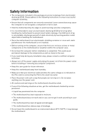
... avoid touching sensitive components. ∙∙It is recommended to wear an electrostatic discharge (ESD) wrist strap when handling the motherboard to ensure successful computer assembly. ∙∙Ensure that all components are no loose screws or metal components on it work ...is indicated on the PSU, before installing or removing any of the following instructions to prevent electrostatic damage. Loose connections may damage the motherboard. 3 Safety Information ∙∙The components included in this package are prone to the electrical outlet. ∙∙Place the ...
... avoid touching sensitive components. ∙∙It is recommended to wear an electrostatic discharge (ESD) wrist strap when handling the motherboard to ensure successful computer assembly. ∙∙Ensure that all components are no loose screws or metal components on it work ...is indicated on the PSU, before installing or removing any of the following instructions to prevent electrostatic damage. Loose connections may damage the motherboard. 3 Safety Information ∙∙The components included in this package are prone to the electrical outlet. ∙∙Place the ...
User Manual
Page 14
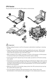
... work properly to protect the CPU from the power outlet before booting your system. ∙∙Overheating can seriously damage the CPU and motherboard. A CPU heatsink is not installed, always protect the CPU socket pins by covering the socket with the plastic cap. ∙∙...CPU, always remember to the documentation in the heatsink/ cooler package for more details about installation. 13 MSI will deal with Return Merchandise Authorization (RMA) requests if only the motherboard comes with the CPU before installing or removing the CPU. ∙∙Please retain the CPU protective...
... work properly to protect the CPU from the power outlet before booting your system. ∙∙Overheating can seriously damage the CPU and motherboard. A CPU heatsink is not installed, always protect the CPU socket pins by covering the socket with the plastic cap. ∙∙...CPU, always remember to the documentation in the heatsink/ cooler package for more details about installation. 13 MSI will deal with Return Merchandise Authorization (RMA) requests if only the motherboard comes with the CPU before installing or removing the CPU. ∙∙Please retain the CPU protective...
User Manual
Page 16
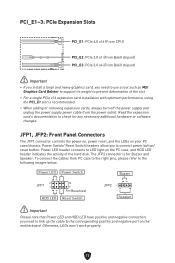
... JFP2 1 Speaker ⚠⚠Important Please note that Power LED and HDD LED have positive and negative connection, you need to use a tool such as MSI Graphics Card Bolster to support its weight to prevent deformation of the hard disk. JFP1, JFP2: Front Panel Connectors The JFP1 connector controls the power...;∙If you install a large and heavy graphics card, you need to link up the cable to the corresponding positive and negative port on the motherboard. Read the expansion card's documentation to check for Buzzer and Speaker. To connect the cables from the power outlet.
... JFP2 1 Speaker ⚠⚠Important Please note that Power LED and HDD LED have positive and negative connection, you need to use a tool such as MSI Graphics Card Bolster to support its weight to prevent deformation of the hard disk. JFP1, JFP2: Front Panel Connectors The JFP1 connector controls the power...;∙If you install a large and heavy graphics card, you need to link up the cable to the corresponding positive and negative port on the motherboard. Read the expansion card's documentation to check for Buzzer and Speaker. To connect the cables from the power outlet.
User Manual
Page 19
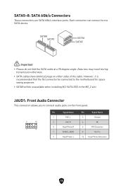
... cable at a 90-degree angle. However, it is recommended that the flat connector be connected to one SATA device. Each connector can connect to the motherboard for space saving purposes. ∙∙SATA8 will be unavailable when installing M.2 SATA SSD in the M2_2 slot. JAUD1: Front Audio Connector This connector allows...
... cable at a 90-degree angle. However, it is recommended that the flat connector be connected to one SATA device. Each connector can connect to the motherboard for space saving purposes. ∙∙SATA8 will be unavailable when installing M.2 SATA SSD in the M2_2 slot. JAUD1: Front Audio Connector This connector allows...
User Manual
Page 20
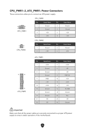
CPU_PWR1~2, ATX_PWR1: Power Connectors These connectors allow you to ensure stable operation of the motherboard. 19 CPU_PWR1 8 5 4 1 CPU_PWR1 Pin Signal Name Pin Signal Name 1 Ground 2 Ground 3 Ground 4 Ground 5 +12V 6 +12V 7 +12V 8 +12V 4 3 2 1 CPU_PWR2 CPU_PWR2 Pin Signal Name Pin Signal Name 1 ...
CPU_PWR1~2, ATX_PWR1: Power Connectors These connectors allow you to ensure stable operation of the motherboard. 19 CPU_PWR1 8 5 4 1 CPU_PWR1 Pin Signal Name Pin Signal Name 1 Ground 2 Ground 3 Ground 4 Ground 5 +12V 6 +12V 7 +12V 8 +12V 4 3 2 1 CPU_PWR2 CPU_PWR2 Pin Signal Name Pin Signal Name 1 ...
User Manual
Page 22
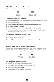
... 5-10 seconds. 3. Connect the JCI1 connector to select Yes. 6. JBAT1: Clear CMOS (Reset BIOS) Jumper There is CMOS memory onboard that is turned on the motherboard to save and exit and then press the Enter key to select Yes. JCI1: Chassis Intrusion Connector This connector allows you want to clear the...
... 5-10 seconds. 3. Connect the JCI1 connector to select Yes. 6. JBAT1: Clear CMOS (Reset BIOS) Jumper There is CMOS memory onboard that is turned on the motherboard to save and exit and then press the Enter key to select Yes. JCI1: Chassis Intrusion Connector This connector allows you want to clear the...

User Manual
Page 28
...8729;∙Supports unlimited number of partitions. ∙∙Supports full capabilities of the new chipset capabilities. ⚠⚠Important The term BIOS in this motherboard supports only Windows 10/ Windows 11 64-bit operating system. ∙∙ Older graphics card - Incompatible UEFI cases ∙∙ 32-bit ...process. 3. Press Delete key when the Press DEL key to enter Setup Menu, F11 to take full advantage of new devices - The MSI UEFI BIOS uses UEFI as the default boot mode to enter Boot Menu message appears on your graphics card. Power on the screen during...
...8729;∙Supports unlimited number of partitions. ∙∙Supports full capabilities of the new chipset capabilities. ⚠⚠Important The term BIOS in this motherboard supports only Windows 10/ Windows 11 64-bit operating system. ∙∙ Older graphics card - Incompatible UEFI cases ∙∙ 32-bit ...process. 3. Press Delete key when the Press DEL key to enter Setup Menu, F11 to take full advantage of new devices - The MSI UEFI BIOS uses UEFI as the default boot mode to enter Boot Menu message appears on your graphics card. Power on the screen during...
User Manual
Page 30
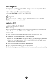
... and press Ctrl + F5 key during POST and click on Yes to start recovering BIOS. 5. Click the M-FLASH button and click on the motherboard. ⚠⚠Important Be sure the computer is 100% completed, the system will reboot automatically. 29 Updating BIOS Updating BIOS with M-FLASH Before ...download the latest BIOS file that contains the update file into the USB flash drive. Insert the USB flash drive that matches your motherboard model from MSI website. Resetting BIOS You might need to restore the default BIOS settings to solve certain problems. There are several ways to reset...
... and press Ctrl + F5 key during POST and click on Yes to start recovering BIOS. 5. Click the M-FLASH button and click on the motherboard. ⚠⚠Important Be sure the computer is 100% completed, the system will reboot automatically. 29 Updating BIOS Updating BIOS with M-FLASH Before ...download the latest BIOS file that contains the update file into the USB flash drive. Insert the USB flash drive that matches your motherboard model from MSI website. Resetting BIOS You might need to restore the default BIOS settings to solve certain problems. There are several ways to reset...


