
User Manual
Page 13
...: USB 3.2 Gen2 Type-C Connector 42 JUSB3~4: USB 3.2 Gen1 Connectors 43 JUSB1~2: USB 2.0 Connectors 43 POWER1, RESET1: Power Button, Reset Button 44 JBAT1: Clear CMOS (Reset BIOS) Jumper 44 JCI1: Chassis Intrusion Connector 45 Contents 13
...: USB 3.2 Gen2 Type-C Connector 42 JUSB3~4: USB 3.2 Gen1 Connectors 43 JUSB1~2: USB 2.0 Connectors 43 POWER1, RESET1: Power Button, Reset Button 44 JBAT1: Clear CMOS (Reset BIOS) Jumper 44 JCI1: Chassis Intrusion Connector 45 Contents 13
User Manual
Page 14
... 51 ACPI States Codes 55 Installing OS, Drivers & Utilities 56 Installing Windows® 10 56 Installing Drivers 56 Installing Utilities 56 BIOS Setup ...57 Entering BIOS Setup 57 Resetting BIOS...58 Updating BIOS...58 EZ Mode ...59 Advanced Mode ...61 SETTINGS...62 Advanced...62 Boot...67 Security ...68 Save & Exit...69 OC...70 M-FLASH...
... 51 ACPI States Codes 55 Installing OS, Drivers & Utilities 56 Installing Windows® 10 56 Installing Drivers 56 Installing Utilities 56 BIOS Setup ...57 Entering BIOS Setup 57 Resetting BIOS...58 Updating BIOS...58 EZ Mode ...59 Advanced Mode ...61 SETTINGS...62 Advanced...62 Boot...67 Security ...68 Save & Exit...69 OC...70 M-FLASH...

User Manual
Page 19
... E-ATX Form Factor y 12 in . (30.5 cm x 27.2 cm) y 1x 256 Mb flash y UEFI AMI BIOS y ACPI 6.1, SMBIOS 2.8 y Multi-language y Drivers y CREATOR CENTER y Nahimic Audio y CPU-Z MSI GAMING y MSI App Player (BlueStacks) y Google Chrome™, Google Toolbar, Google Drive y Norton™ Internet Security Solution y CREATOR OPTIMIZATION... y High Performance y Hardware Monitor y LAN Manager y True Color y Mystic Light y Live update Please refer to http://download.msi. x 10.7 in . Continued on next page Specifications 19 pdf for more details. com/manual/mb/CREATORCENTER.
... E-ATX Form Factor y 12 in . (30.5 cm x 27.2 cm) y 1x 256 Mb flash y UEFI AMI BIOS y ACPI 6.1, SMBIOS 2.8 y Multi-language y Drivers y CREATOR CENTER y Nahimic Audio y CPU-Z MSI GAMING y MSI App Player (BlueStacks) y Google Chrome™, Google Toolbar, Google Drive y Norton™ Internet Security Solution y CREATOR OPTIMIZATION... y High Performance y Hardware Monitor y LAN Manager y True Color y Mystic Light y Live update Please refer to http://download.msi. x 10.7 in . Continued on next page Specifications 19 pdf for more details. com/manual/mb/CREATORCENTER.

User Manual
Page 21
... CPU Power y Gamer Experience ƒ GAMING HOTKEY ƒ GAMING MOUSE Control ƒ SPEED UP ƒ Total Fan Control ƒ Live Update ƒ APP Player y BIOS ƒ Click BIOS 5 JCORSAIR1 Connector Specification Supporting CORSAIR RGB Products Lighting Node PRO LED Strip HD120 RGB Fan SP120 RGB Fan LL120 RGB Fan Maximum connection 20...
... CPU Power y Gamer Experience ƒ GAMING HOTKEY ƒ GAMING MOUSE Control ƒ SPEED UP ƒ Total Fan Control ƒ Live Update ƒ APP Player y BIOS ƒ Click BIOS 5 JCORSAIR1 Connector Specification Supporting CORSAIR RGB Products Lighting Node PRO LED Strip HD120 RGB Fan SP120 RGB Fan LL120 RGB Fan Maximum connection 20...

User Manual
Page 24
Press and hold the Clear CMOS button for about 5-10 seconds to reset BIOS to default values. Rear I /O Panel LAN Port LED Status Table Link/ Activity LED Status Off On Blinking Description No link Linked Data activity Speed LED ...
Press and hold the Clear CMOS button for about 5-10 seconds to reset BIOS to default values. Rear I /O Panel LAN Port LED Status Table Link/ Activity LED Status Off On Blinking Description No link Linked Data activity Speed LED ...

User Manual
Page 29
..., SYS_FAN1~7 Fan Connectors CPU_PWR1~2, ATX_PWR1 Power Connectors CPU Socket AM4 Socket DIMMA1/A2/B1/B2 DIMM Slots JAUD1 Front Audio Connector JBAT1 Clear CMOS (Reset BIOS) Jumper JCI1 Chassis Intrusion Connector JCORSAIR1 CORSAIR Connector JFP1, JFP2 Front Panel Connectors JPWRLED1 LED power input JRAINBOW1~2 Addressable RGB LED connectors JRGB1 RGB LED...
..., SYS_FAN1~7 Fan Connectors CPU_PWR1~2, ATX_PWR1 Power Connectors CPU Socket AM4 Socket DIMMA1/A2/B1/B2 DIMM Slots JAUD1 Front Audio Connector JBAT1 Clear CMOS (Reset BIOS) Jumper JCI1 Chassis Intrusion Connector JCORSAIR1 CORSAIR Connector JFP1, JFP2 Front Panel Connectors JPWRLED1 LED power input JRAINBOW1~2 Addressable RGB LED connectors JRGB1 RGB LED...

User Manual
Page 30
...Distance from the power outlet before booting your system. Important y When changing the processor, the system configuration could be cleared and reset BIOS to default values, due to install a CPU heatsink. A CPU heatsink is designed to protect the CPU from overheating. y This ...motherboard is necessary to assist in the heatsink/ cooler package for motherboard placement. MSI® does not guarantee the damages or risks caused by inadequate operation beyond product specifications is the Pin 1 indicator. y Always unplug...
...Distance from the power outlet before booting your system. Important y When changing the processor, the system configuration could be cleared and reset BIOS to default values, due to install a CPU heatsink. A CPU heatsink is designed to protect the CPU from overheating. y This ...motherboard is necessary to assist in the heatsink/ cooler package for motherboard placement. MSI® does not guarantee the damages or risks caused by inadequate operation beyond product specifications is the Pin 1 indicator. y Always unplug...

User Manual
Page 31
y Due to protect the processor. Go to BIOS and find the DRAM Frequency to set the memory frequency if you want to operate the memory at the marked or at a lower frequency than ... on the processor specification, the Memory DIMM voltage below 1.35V is suggested to chipset resource usage, the available capacity of Components 31 Please refer www.msi.com for full DIMMs installation or overclocking. y Based on compatible memory.
y Due to protect the processor. Go to BIOS and find the DRAM Frequency to set the memory frequency if you want to operate the memory at the marked or at a lower frequency than ... on the processor specification, the Memory DIMM voltage below 1.35V is suggested to chipset resource usage, the available capacity of Components 31 Please refer www.msi.com for full DIMMs installation or overclocking. y Based on compatible memory.

User Manual
Page 41
... speed with speed control signal. Select PWM mode or DC mode There are gradient points of Components 41 However, you to adjust fan speed in BIOS > HARDWARE MONITOR. CPU_FAN1, PUMP_FAN1, SYS_FAN1~7: Fan Connectors Fan connectors can automatically detect PWM and DC mode. Pin definition of fan connectors PWM Mode pin definition...
... speed with speed control signal. Select PWM mode or DC mode There are gradient points of Components 41 However, you to adjust fan speed in BIOS > HARDWARE MONITOR. CPU_FAN1, PUMP_FAN1, SYS_FAN1~7: Fan Connectors Fan connectors can automatically detect PWM and DC mode. Pin definition of fan connectors PWM Mode pin definition...

User Manual
Page 44
If you to power on / reset the computer. Keep Data (default) Clear CMOS/ Reset BIOS Resetting BIOS to short JBAT1 for about 5-10 seconds. 3. Use a jumper cap to default values 1. Remove the jumper cap from a battery located on the computer. 44 Overview ...of Components Reset Reset button Power button JBAT1: Clear CMOS (Reset BIOS) Jumper There is CMOS memory onboard that is external powered from JBAT1. 4. Power off the computer and unplug the power cord 2. Plug the power cord...
If you to power on / reset the computer. Keep Data (default) Clear CMOS/ Reset BIOS Resetting BIOS to short JBAT1 for about 5-10 seconds. 3. Use a jumper cap to default values 1. Remove the jumper cap from a battery located on the computer. 44 Overview ...of Components Reset Reset button Power button JBAT1: Clear CMOS (Reset BIOS) Jumper There is CMOS memory onboard that is external powered from JBAT1. 4. Power off the computer and unplug the power cord 2. Plug the power cord...

User Manual
Page 45
Connect the JCI1 connector to the chassis intrusion switch/ sensor on . Close the chassis cover. 3. Set Chassis Intrusion to BIOS > SETTINGS > Security > Chassis Intrusion Configuration. 4. Once the chassis cover is opened again, a warning message will be ...pin3 12 Ground 13 LPC Frame 14 Ground Overview of Components 45 Go to Reset. 3. Resetting the chassis intrusion warning 1. Set Chassis Intrusion to BIOS > SETTINGS > Security > Chassis Intrusion Configuration. 2. JTPM1: TPM Module Connector This connector is turned on the chassis. 2. Normal (default) Trigger...
Connect the JCI1 connector to the chassis intrusion switch/ sensor on . Close the chassis cover. 3. Set Chassis Intrusion to BIOS > SETTINGS > Security > Chassis Intrusion Configuration. 4. Once the chassis cover is opened again, a warning message will be ...pin3 12 Ground 13 LPC Frame 14 Ground Overview of Components 45 Go to Reset. 3. Resetting the chassis intrusion warning 1. Set Chassis Intrusion to BIOS > SETTINGS > Security > Chassis Intrusion Configuration. 2. JTPM1: TPM Module Connector This connector is turned on the chassis. 2. Normal (default) Trigger...

User Manual
Page 57
...Save Overclocking Profile F10: Save Change and Reset* F12: Take a screenshot and save it provides the modification information. Important y BIOS items are familiar with BIOS. Entering BIOS Setup Press Delete key, when the Press DEL key to enter Setup Menu, F11 to USB flash drive (FAT/ FAT32 format...appears and it to enter Boot Menu message appears on the screen during the boot process. y The pictures in normal conditions. BIOS Setup 57 BIOS Setup The default settings offer the optimal performance for system stability in this chapter are for reference only and may be for reference ...
...Save Overclocking Profile F10: Save Change and Reset* F12: Take a screenshot and save it provides the modification information. Important y BIOS items are familiar with BIOS. Entering BIOS Setup Press Delete key, when the Press DEL key to enter Setup Menu, F11 to USB flash drive (FAT/ FAT32 format...appears and it to enter Boot Menu message appears on the screen during the boot process. y The pictures in normal conditions. BIOS Setup 57 BIOS Setup The default settings offer the optimal performance for system stability in this chapter are for reference only and may be for reference ...
User Manual
Page 58
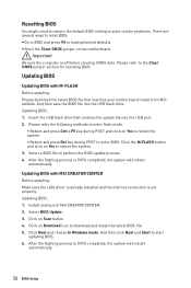
.... ƒ Reboot and press Ctrl + F5 key during POST and click on Yes to perform the BIOS update process. 4. Click on the motherboard. Updating BIOS Updating BIOS with MSI CREATOR CENTER Before updating: Make sure the LAN driver is already installed and the Internet connection is 100%... completed, the system will restart automatically. 58 BIOS Setup Insert the USB flash drive that matches your motherboard model from MSI website. Install and launch MSI CREATOR CENTER. 2. Click Next and choose In Windows mode. After the flashing process...
.... ƒ Reboot and press Ctrl + F5 key during POST and click on Yes to perform the BIOS update process. 4. Click on the motherboard. Updating BIOS Updating BIOS with MSI CREATOR CENTER Before updating: Make sure the LAN driver is already installed and the Internet connection is 100%... completed, the system will restart automatically. 58 BIOS Setup Insert the USB flash drive that matches your motherboard model from MSI website. Install and launch MSI CREATOR CENTER. 2. Click Next and choose In Windows mode. After the flashing process...
User Manual
Page 59
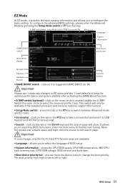
... the item listing. allows you to exit search page. Move the mouse over a blank space and right click the mouse to select the language of BIOS setup. Important In search page, only the F6, F10 and F12 function keys are available. y Language - y System information - The boot priority from high to ... it to toggle the GAME BOOST for OC. shows the CPU/ DDR speed, CPU/ MB temperature, MB/ CPU type, memory size, CPU/ DDR voltage, BIOS version and build date. press this function. EZ Mode At EZ mode, it provides the basic system information and allows you to change the boot...
... the item listing. allows you to exit search page. Move the mouse over a blank space and right click the mouse to select the language of BIOS setup. Important In search page, only the F6, F10 and F12 function keys are available. y Language - y System information - The boot priority from high to ... it to toggle the GAME BOOST for OC. shows the CPU/ DDR speed, CPU/ MB temperature, MB/ CPU type, memory size, CPU/ DDR voltage, BIOS version and build date. press this function. EZ Mode At EZ mode, it provides the basic system information and allows you to change the boot...

User Manual
Page 60
... page 1. allows you to a favorite page (Favorite 1~5) 1. click on favorite page (Favorite 1~5) 2. Move the mouse over a BIOS item not only on BIOS menu but also on OK. 60 BIOS Setup y Function buttons - Right-click or press F2 key. 3. y M-Flash - Choose a favorite page and click on their respective... ROM, CSM/UEFI, ErP Ready, AHCI, RAID, Indication LED Control and RGB Light Control by percentage. click on left side to select a BIOS menu (e.g. y Information display - click on the CPU, Memory, Storage, Fan Info and Help buttons on this button to display the M-Flash ...
... page 1. allows you to a favorite page (Favorite 1~5) 1. click on favorite page (Favorite 1~5) 2. Move the mouse over a BIOS item not only on BIOS menu but also on OK. 60 BIOS Setup y Function buttons - Right-click or press F2 key. 3. y M-Flash - Choose a favorite page and click on their respective... ROM, CSM/UEFI, ErP Ready, AHCI, RAID, Indication LED Control and RGB Light Control by percentage. click on left side to select a BIOS menu (e.g. y Information display - click on the CPU, Memory, Storage, Fan Info and Help buttons on this button to display the M-Flash ...

User Manual
Page 61
...MONITOR - y Menu display - allows you to adjust the frequency and voltage. provides BIOS setting items and information to update BIOS with a USB flash drive. ƒ OC PROFILE - BIOS Setup 61 A-XMP switch Setup Mode switch Screenshot Search Language System information GAME BOOST switch... Boot device priority bar BIOS menu selection BIOS menu selection Menu display y BIOS menu selection - allows you to set the speeds of fans and monitor voltages of installed devices on...
...MONITOR - y Menu display - allows you to adjust the frequency and voltage. provides BIOS setting items and information to update BIOS with a USB flash drive. ƒ OC PROFILE - BIOS Setup 61 A-XMP switch Setup Mode switch Screenshot Search Language System information GAME BOOST switch... Boot device priority bar BIOS menu selection BIOS menu selection Menu display y BIOS menu selection - allows you to set the speeds of fans and monitor voltages of installed devices on...

User Manual
Page 62
... Settings Sets PCI, PCI express interface protocol and latency timer. through Dec. Use tab key to 31 can be keyed by BIOS. f System Information Shows detailed system information, including CPU type, BIOS version, and Memory (read only). The format is . The date from 1 to switch between time elements. Use tab key to...
... Settings Sets PCI, PCI express interface protocol and latency timer. through Dec. Use tab key to 31 can be keyed by BIOS. f System Information Shows detailed system information, including CPU type, BIOS version, and Memory (read only). The format is . The date from 1 to switch between time elements. Use tab key to...

User Manual
Page 63
...[Auto] Sets PCI Express protocol of PCH-controlled PCIe x16 slots to match different installed devices. [Auto] This item will be configured automatically by BIOS. [Gen1] Enables PCIe Gen1 support only. [Gen2] Enables PCIe Gen2 support only. [Gen3] Enables PCIe Gen3 support only. [Gen4] Enables ...[Dual Color] The power LED turns to another color to indicate the S3 state. [Blinking] The power LED blinks to be configured automatically by BIOS. [Gen1] Enables PCIe Gen1 support only. [Gen2] Enables PCIe Gen2 support only. [Gen3] Enables PCIe Gen3 support only. [Gen4] Enables ...
...[Auto] Sets PCI Express protocol of PCH-controlled PCIe x16 slots to match different installed devices. [Auto] This item will be configured automatically by BIOS. [Gen1] Enables PCIe Gen1 support only. [Gen2] Enables PCIe Gen2 support only. [Gen3] Enables PCIe Gen3 support only. [Gen4] Enables ...[Dual Color] The power LED turns to another color to indicate the S3 state. [Blinking] The power LED blinks to be configured automatically by BIOS. [Gen1] Enables PCIe Gen1 support only. [Gen2] Enables PCIe Gen2 support only. [Gen3] Enables PCIe Gen3 support only. [Gen4] Enables ...
User Manual
Page 64
... appear when Network Stack is Enabled. [Enabled] Enables UEFI network stack. [Disabled] Disables UEFI network stack. This item will be unavailable under legacy mode. 64 BIOS Setup Press Enter to enhance the speed and performance of the onboard SATA controller. [AHCI Mode] Specify the AHCI mode for optimizing IPv4 / IPv6 function...
... appear when Network Stack is Enabled. [Enabled] Enables UEFI network stack. [Disabled] Disables UEFI network stack. This item will be unavailable under legacy mode. 64 BIOS Setup Press Enter to enhance the speed and performance of the onboard SATA controller. [AHCI Mode] Specify the AHCI mode for optimizing IPv4 / IPv6 function...
User Manual
Page 65
... support S4 & S5 wake up by USB and PCIe devices. [Disabled] Disables this function. This sub-menu will appear when BIOS UEFI/CSM Mode is enabled. BIOS Setup 65 fSystem Power Fault Protection [Disabled] Enables or disables the system to prevent the unauthorized accessing. fBIOS UEFI/CSM Mode [CSM...] Select CSM or UEFI for different sleep modes. fWake Up Event By [BIOS] Selects the wake up event by BIOS or operating system. [BIOS] Activates the following items, set wake up events of ErP Ready and AC Power Loss behaviors. Press Enter to...
... support S4 & S5 wake up by USB and PCIe devices. [Disabled] Disables this function. This sub-menu will appear when BIOS UEFI/CSM Mode is enabled. BIOS Setup 65 fSystem Power Fault Protection [Disabled] Enables or disables the system to prevent the unauthorized accessing. fBIOS UEFI/CSM Mode [CSM...] Select CSM or UEFI for different sleep modes. fWake Up Event By [BIOS] Selects the wake up event by BIOS or operating system. [BIOS] Activates the following items, set wake up events of ErP Ready and AC Power Loss behaviors. Press Enter to...


