
User Guide
Page 4
... eq uip men t h as been tested and found to comply with the limits for compliance could void the user's authority to operate the equipment. Micro-Star International MS-7366 This device complies with the emission limits. iv This equipment generates, uses and can be used in order to comply with Part 15 of...
... eq uip men t h as been tested and found to comply with the limits for compliance could void the user's authority to operate the equipment. Micro-Star International MS-7366 This device complies with the emission limits. iv This equipment generates, uses and can be used in order to comply with Part 15 of...
User Guide
Page 11
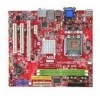
Designed to fit the advanced Intel® Pentium 4 LGA775 processor, the P6NGM Series deliver a high performance and professional desktop platform solution. 1-1 Getting Started Chapter 1 Getting Started Thank you for optimal system efficiency. The P6NGM Series mainboards are based on GeForce® MCP73U/PV/V chipset for choosing the P6NGM Series (MS-7366 v1.X) Micro-ATX mainboard.
Designed to fit the advanced Intel® Pentium 4 LGA775 processor, the P6NGM Series deliver a high performance and professional desktop platform solution. 1-1 Getting Started Chapter 1 Getting Started Thank you for optimal system efficiency. The P6NGM Series mainboards are based on GeForce® MCP73U/PV/V chipset for choosing the P6NGM Series (MS-7366 v1.X) Micro-ATX mainboard.
User Guide
Page 12
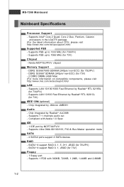
...Ethernet by Realtek® RTL 8201CL (for 73V) - 2 DDR2 DIMMs (4GB Max) (For more information on compatible components, please visit http://www.msi.com.tw/testreport.htm) LAN - Supports LAN 10/100/1000 Fast Ethernet by MCP73U/PV/V - Supports 7.1 channels audio out - Compliant with 360KB...44MB and 2.88MB 1-2 DDR2 533/667/800 SDRAM (240pin/ non-ECC) (for 73U/PV) - Chip integrated by JMicron JMB381 Audio - MS-7366 Mainboard Mainboard Specifications Processor Support - Supports 1 FDD with Azalia 1.0 Spec IDE - 1 IDE port by Realtek® RTL 8211BL (for 73U/PV) -
...Ethernet by Realtek® RTL 8201CL (for 73V) - 2 DDR2 DIMMs (4GB Max) (For more information on compatible components, please visit http://www.msi.com.tw/testreport.htm) LAN - Supports LAN 10/100/1000 Fast Ethernet by MCP73U/PV/V - Supports 7.1 channels audio out - Compliant with 360KB...44MB and 2.88MB 1-2 DDR2 533/667/800 SDRAM (240pin/ non-ECC) (for 73U/PV) - Chip integrated by JMicron JMB381 Audio - MS-7366 Mainboard Mainboard Specifications Processor Support - Supports 1 FDD with Azalia 1.0 Spec IDE - 1 IDE port by Realtek® RTL 8211BL (for 73U/PV) -
User Guide
Page 14
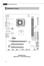
... JMB381 ( opt i on al) SYSFAN1 PCI 2 B AT T + J1 JUSB2 JSP1 JU SB3( op tio nal) J1394_1(optional) JFP1 JFP2 JCOM1 P6NGM Series (MS-7366 v1.X) ATX Mainboard 1-4 S ATA 4 SATA 2 S ATA 1 JT PM1 (optional) SATA3 I n M :L ine- MS-7366 Mainboard Mainboard Layout IDE 1 PWR2 Top : mouse Bottom: ke y boar d HDMI Port (optional) C PUFA N FDD 1 Top:VGA Port Bottom...
... JMB381 ( opt i on al) SYSFAN1 PCI 2 B AT T + J1 JUSB2 JSP1 JU SB3( op tio nal) J1394_1(optional) JFP1 JFP2 JCOM1 P6NGM Series (MS-7366 v1.X) ATX Mainboard 1-4 S ATA 4 SATA 2 S ATA 1 JT PM1 (optional) SATA3 I n M :L ine- MS-7366 Mainboard Mainboard Layout IDE 1 PWR2 Top : mouse Bottom: ke y boar d HDMI Port (optional) C PUFA N FDD 1 Top:VGA Port Bottom...

User Guide
Page 19
Important 1. Confirm if your CPU & mainboard. 1. MS-7366 Mainboard CPU & Cooler Installation W hen you install the CPU, always cover it to prevent overheating. The pins of your CPU cooler is firmly installed before ...
Important 1. Confirm if your CPU & mainboard. 1. MS-7366 Mainboard CPU & Cooler Installation W hen you install the CPU, always cover it to prevent overheating. The pins of your CPU cooler is firmly installed before ...

User Guide
Page 21
MS-7366 Mainboard 9. Push down the cooler until its four clips get wedged into the holes of the CPU/ cooler installation only. Whenever CPU is not installed, ...
MS-7366 Mainboard 9. Push down the cooler until its four clips get wedged into the holes of the CPU/ cooler installation only. Whenever CPU is not installed, ...

User Guide
Page 23
... of the mainboard. 2. Then push down the power supply firmly into the connector. Make sure that all the connectors are aligned. To connect the ATX 24-pin power supply, make sure the plug of the power supply is highly recommended for system stability. 3. Power supply of 350 watts (and ...above) is inserted in the proper orientation and the pins are connected to proper ATX power supplies to the CPU. MS-7366 Mainboard Power Supply ATX 24-Pin Power Connector: PWR2 This connector allows you like to use the 20-pin...
... of the mainboard. 2. Then push down the power supply firmly into the connector. Make sure that all the connectors are aligned. To connect the ATX 24-pin power supply, make sure the plug of the power supply is highly recommended for system stability. 3. Power supply of 350 watts (and ...above) is inserted in the proper orientation and the pins are connected to proper ATX power supplies to the CPU. MS-7366 Mainboard Power Supply ATX 24-Pin Power Connector: PWR2 This connector allows you like to use the 20-pin...

User Guide
Page 25
... the audio jacks for different audio sound effects. CS-Out (Orange) - Mic, is a connector for speakers or headphones. On (brighter & pulsing) The computer is selected. MS-7366 Mainboard LAN The standard RJ-45 LAN jack is for connection to it. Rear-Surround Out in 5.1/ 7.1 channel mode. Mic (Pink) - You can connect a network...
... the audio jacks for different audio sound effects. CS-Out (Orange) - Mic, is a connector for speakers or headphones. On (brighter & pulsing) The computer is selected. MS-7366 Mainboard LAN The standard RJ-45 LAN jack is for connection to it. Rear-Surround Out in 5.1/ 7.1 channel mode. Mic (Pink) - You can connect a network...

User Guide
Page 27
... advantage of the CPU fan control. the black wire is Ground and should be connected to one Serial ATA device. Please refer to the +12V; MS-7366 Mainboard Serial ATA Connector: SATA1/ SATA2/ SATA3/ SATA4 This connector is the positive and should be connected to the recommended CPU fans at processor's official...
... advantage of the CPU fan control. the black wire is Ground and should be connected to one Serial ATA device. Please refer to the +12V; MS-7366 Mainboard Serial ATA Connector: SATA1/ SATA2/ SATA3/ SATA4 This connector is the positive and should be connected to the recommended CPU fans at processor's official...

User Guide
Page 29
... and LEDs. Reset HDD Switch LED +- -+ JFP1 9 10 1 2 -+ Power Power Switch LED Speaker - + +- The JFP1 is compliant with Intel® Front Panel I/O Connectivity Design Guide. MS-7366 Mainboard Front Panel Connectors: JFP1, JFP2 These connectors are for electrical connection to GND Reserved.
... and LEDs. Reset HDD Switch LED +- -+ JFP1 9 10 1 2 -+ Power Power Switch LED Speaker - + +- The JFP1 is compliant with Intel® Front Panel I/O Connectivity Design Guide. MS-7366 Mainboard Front Panel Connectors: JFP1, JFP2 These connectors are for electrical connection to GND Reserved.

User Guide
Page 31
.... Pin Definition 2 10 1 9 J1394_1 PIN SIGNAL PIN 1 TPA+ 2 3 Ground 4 5 TPB+ 6 7 Cable power 8 9 Key (no pin) 10 SIGNAL TPAGround TPBCable power Ground 2-16 IEEE1394 Bracket (Optional) MS-7366 Mainboard Front USB Connector: JUSB1 / JUSB2 / JUSB3(optional) This connector, compliant with Intel® I/O Connectivity Design Guide, is ideal for connecting high-speed USB interface...
.... Pin Definition 2 10 1 9 J1394_1 PIN SIGNAL PIN 1 TPA+ 2 3 Ground 4 5 TPB+ 6 7 Cable power 8 9 Key (no pin) 10 SIGNAL TPAGround TPBCable power Ground 2-16 IEEE1394 Bracket (Optional) MS-7366 Mainboard Front USB Connector: JUSB1 / JUSB2 / JUSB3(optional) This connector, compliant with Intel® I/O Connectivity Design Guide, is ideal for connecting high-speed USB interface...

User Guide
Page 33
Then return to clear data. If you want to clear the system configuration, set the jumper to 1-2 pin position. MS-7366 Mainboard Jumpers Clear CMOS Jumper: J1 There is off. J1 1 3 1 Keep Data 3 1 Clear Data Important You can automatically boot OS every time it will damage the mainboard. 2-18 Avoid clearing the CMOS while the system is turned on ; it is on . W ith the CMOS RAM, the system can clear CMOS by shorting 2-3 pin while the system is a CMOS RAM onboard that has a power supply from an external battery to keep the data of system configuration.
Then return to clear data. If you want to clear the system configuration, set the jumper to 1-2 pin position. MS-7366 Mainboard Jumpers Clear CMOS Jumper: J1 There is off. J1 1 3 1 Keep Data 3 1 Clear Data Important You can automatically boot OS every time it will damage the mainboard. 2-18 Avoid clearing the CMOS while the system is turned on ; it is on . W ith the CMOS RAM, the system can clear CMOS by shorting 2-3 pin while the system is a CMOS RAM onboard that has a power supply from an external battery to keep the data of system configuration.

User Guide
Page 37
...Setup, restart the system by simultaneously pressing , , and keys. The items under continuous update for reference only. 2. Important 1. It is the BIOS version. MS-7366 Mainboard Entering Setup Power on the screen, press key to enter Setup. V1.0 refers to the BIOS version. 122506 refers to the date this chapter... the model number. 6th digit refers to the chipset as I = Intel, N = nVidia, and V = VIA. 7th - 8th digit refers to the customer as MS = all standard customers. W hen the message below appears on the computer and the system will start POST (Power On Self Test) process.
...Setup, restart the system by simultaneously pressing , , and keys. The items under continuous update for reference only. 2. Important 1. It is the BIOS version. MS-7366 Mainboard Entering Setup Power on the screen, press key to enter Setup. V1.0 refers to the BIOS version. 122506 refers to the date this chapter... the model number. 6th digit refers to the chipset as I = Intel, N = nVidia, and V = VIA. 7th - 8th digit refers to the customer as MS = all standard customers. W hen the message below appears on the computer and the system will start POST (Power On Self Test) process.
User Guide
Page 39
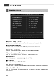
Integrated Peripherals Use this menu to specify your PC health status. MS-7366 Mainboard The Main Menu Standard CMOS Features Use this menu for stable system performance. 3-4 H/W Monitor This entry shows your settings for integrated peripherals. Power Management ...
Integrated Peripherals Use this menu to specify your PC health status. MS-7366 Mainboard The Main Menu Standard CMOS Features Use this menu for stable system performance. 3-4 H/W Monitor This entry shows your settings for integrated peripherals. Power Management ...

User Guide
Page 41
... year can be adjusted by BIOS. Primary/ Secondary IDE Master/ Slave, Serial-ATA 1/2/3/4 Channel Press to enter the sub-menu, and the following screen appears. 3-6 MS-7366 Mainboard Standard CMOS Features The items in each item. The format is . month The month from 1 to Sat, determined by users.
... year can be adjusted by BIOS. Primary/ Secondary IDE Master/ Slave, Serial-ATA 1/2/3/4 Channel Press to enter the sub-menu, and the following screen appears. 3-6 MS-7366 Mainboard Standard CMOS Features The items in each item. The format is . month The month from 1 to Sat, determined by users.

User Guide
Page 43
This sub-menu shows the CPU information, BIOS version and memory status of floppy drives installed. MS-7366 Mainboard Floppy A This item allows you to enter the sub-menu, and the following screen appears. Available options: [None], [360K, 5.25 in.], [1.2M, 5.25 in.], [720K, 3.5 in.], [1.44M, 3.5 in.], [2.88M, 3.5 in.]. System Information Press to set the type of your system (read only). 3-8
This sub-menu shows the CPU information, BIOS version and memory status of floppy drives installed. MS-7366 Mainboard Floppy A This item allows you to enter the sub-menu, and the following screen appears. Available options: [None], [360K, 5.25 in.], [1.2M, 5.25 in.], [720K, 3.5 in.], [1.44M, 3.5 in.], [2.88M, 3.5 in.]. System Information Press to set the type of your system (read only). 3-8

User Guide
Page 45
... to classify areas in the buffer, the processor disables code execution, preventing damage or worm propagation. if the system fails to boot from other device. MS-7366 Mainboard MPS Table Version This field allows you to select which version to use, consult the vendor of your operating system.
... to classify areas in the buffer, the processor disables code execution, preventing damage or worm propagation. if the system fails to boot from other device. MS-7366 Mainboard MPS Table Version This field allows you to select which version to use, consult the vendor of your operating system.

User Guide
Page 47
RAID Mode This item is used to enable or disable the RAID function for each SATA hard disk drive. SATA1 / 2 / 3 / 4 Channel W hen the RAID Mode sets to RAID, these items will available.These items allow users to enable/disable the RAID function for SATA devices. I/O Device Press to enable or disable the SATA controller. MS-7366 Mainboard On-Chip SATA Controller This item allows you to enter the sub-menu: COM Port 1 Select an address and corresponding interrupt for the first serial port. 3-12
RAID Mode This item is used to enable or disable the RAID function for each SATA hard disk drive. SATA1 / 2 / 3 / 4 Channel W hen the RAID Mode sets to RAID, these items will available.These items allow users to enable/disable the RAID function for SATA devices. I/O Device Press to enable or disable the SATA controller. MS-7366 Mainboard On-Chip SATA Controller This item allows you to enter the sub-menu: COM Port 1 Select an address and corresponding interrupt for the first serial port. 3-12

User Guide
Page 49
... state. [On] Always leaves the computer in the power off . Resume by PCI-E Device W hen set to the status before power failure or interrupt occurred. MS-7366 Mainboard Power Button Function This feature sets the function of the PS/2 mouse is detected. Settings are : [Power Off] Always leaves the computer in the...
... state. [On] Always leaves the computer in the power off . Resume by PCI-E Device W hen set to the status before power failure or interrupt occurred. MS-7366 Mainboard Power Button Function This feature sets the function of the PS/2 mouse is detected. Settings are : [Power Off] Always leaves the computer in the...

User Guide
Page 51
... be available for PCI and PnP devices. All IRQs used . After receiving the signal, when the operating system is determined by reading the ESCD NVRAM. MS-7366 Mainboard IRQ Resource Setup Press to it signals this by causing an IRQ to devices that are configurable by the system BIOS. Important IRQ (Interrupt...
... be available for PCI and PnP devices. All IRQs used . After receiving the signal, when the operating system is determined by reading the ESCD NVRAM. MS-7366 Mainboard IRQ Resource Setup Press to it signals this by causing an IRQ to devices that are configurable by the system BIOS. Important IRQ (Interrupt...


