User Guide
Page 2
...support.msi.com.tw/ ii Netware® is the intellectual property of M ICRO-STAR INTERNATIONAL. Alternatively, please try the following help resources for FAQ, technical guide, BIOS updates, driver updates, and other countries. Revision History Revision V1.0 Revision History First release Date September 2007 Technical Support If a problem...from the user's manual, please contact your system and no guarantee is given as to make changes without notice. We take every care in the preparation of this document is a registered trademark of Novell, Inc. Visit the MSI website for...
...support.msi.com.tw/ ii Netware® is the intellectual property of M ICRO-STAR INTERNATIONAL. Alternatively, please try the following help resources for FAQ, technical guide, BIOS updates, driver updates, and other countries. Revision History Revision V1.0 Revision History First release Date September 2007 Technical Support If a problem...from the user's manual, please contact your system and no guarantee is given as to make changes without notice. We take every care in the preparation of this document is a registered trademark of Novell, Inc. Visit the MSI website for...
User Guide
Page 8
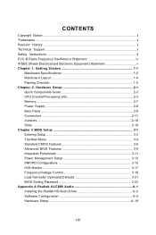
... Quick Components Guide 2-2 CPU (Central Processing Unit 2-3 Memory ...2-7 Power Supply ...2-8 Back Panel ...2-9 Connectors ...2-11 Jumpers ...2-18 Slots ...2-19 Chapter 3 BIOS Setup 3-1 Entering Setup ...3-2 The Main Menu ...3-4 Standard CMOS Features 3-6 Advanced BIOS Features 3-9 Integrated Peripherals 3-11 Power Management Setup 3-13 PNP/PCI Configurations 3-15 H/W Monitor ...3-17 Frequency/Voltage Control 3-18 Load Fail-Safe/ Optimized Defaults 3-21 BIOS Setting Password 3-22 Appendix A Realtek ALC888 Audio A-1 Installing the Realtek HD Audio Driver A-2 Software Configuration...
... Quick Components Guide 2-2 CPU (Central Processing Unit 2-3 Memory ...2-7 Power Supply ...2-8 Back Panel ...2-9 Connectors ...2-11 Jumpers ...2-18 Slots ...2-19 Chapter 3 BIOS Setup 3-1 Entering Setup ...3-2 The Main Menu ...3-4 Standard CMOS Features 3-6 Advanced BIOS Features 3-9 Integrated Peripherals 3-11 Power Management Setup 3-13 PNP/PCI Configurations 3-15 H/W Monitor ...3-17 Frequency/Voltage Control 3-18 Load Fail-Safe/ Optimized Defaults 3-21 BIOS Setting Password 3-22 Appendix A Realtek ALC888 Audio A-1 Installing the Realtek HD Audio Driver A-2 Software Configuration...
User Guide
Page 12
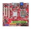
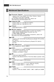
... 1.0 Spec IDE - 1 IDE port by MCP73U/PV/V - Supports 7.1 channels audio out - Chip integrated by JMicron JMB381 Audio - Supports Intel® Core 2 Quad, Core 2 Duo, Pentium, Celeron processors in the LGA775 package. (For the latest information about CPU, please visit http://www.msi.com.tw/cpusupport.htm) Supported FSB - DDR2 533/667/800 SDRAM (240pin/ non-ECC) (for 73V) - 2 DDR2 DIMMs (4GB Max) (For more information on compatible components...
... 1.0 Spec IDE - 1 IDE port by MCP73U/PV/V - Supports 7.1 channels audio out - Chip integrated by JMicron JMB381 Audio - Supports Intel® Core 2 Quad, Core 2 Duo, Pentium, Celeron processors in the LGA775 package. (For the latest information about CPU, please visit http://www.msi.com.tw/cpusupport.htm) Supported FSB - DDR2 533/667/800 SDRAM (240pin/ non-ECC) (for 73V) - 2 DDR2 DIMMs (4GB Max) (For more information on compatible components...
User Guide
Page 24
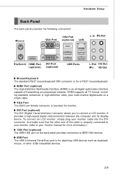
... display device. USB Port The USB (Universal Serial Bus) port is for a PS/2® mouse/keyboard. HDM I Port (optional) The High-Definition Multimedia Interface (HDMI) is an all TV format, including standard, enhanced, or high-definition video, plus multi-channel digital audio on the back panel provides connection to IEEE1394 devices. DVI Port (optional) The DVI (Digital Visual Interface) connector allows you to your monitor manual for monitor. To connect an LCD monitor, simply plug your monitor (refer to connect a LCD monitor. VGA Port...
... display device. USB Port The USB (Universal Serial Bus) port is for a PS/2® mouse/keyboard. HDM I Port (optional) The High-Definition Multimedia Interface (HDMI) is an all TV format, including standard, enhanced, or high-definition video, plus multi-channel digital audio on the back panel provides connection to IEEE1394 devices. DVI Port (optional) The DVI (Digital Visual Interface) connector allows you to your monitor manual for monitor. To connect an LCD monitor, simply plug your monitor (refer to connect a LCD monitor. VGA Port...

User Guide
Page 26
FDD1 IDE Connector: IDE1 This connector supports IDE hard disk drives, optical disk drives and other IDE devices. Hardware Setup Connectors Floppy Disk Drive Connector: FDD1 This connector supports 360KB, 720KB, 1.2MB, 1.44MB or 2.88MB floppy disk drive. Refer to Primary / Slave mode by the vendors for jumper setting instructions. 2-11 IDE1 Important If you install two IDE devices on the same cable, you must configure the drives separately to IDE device's documentation supplied by setting jumpers.
FDD1 IDE Connector: IDE1 This connector supports IDE hard disk drives, optical disk drives and other IDE devices. Hardware Setup Connectors Floppy Disk Drive Connector: FDD1 This connector supports 360KB, 720KB, 1.2MB, 1.44MB or 2.88MB floppy disk drive. Refer to Primary / Slave mode by the vendors for jumper setting instructions. 2-11 IDE1 Important If you install two IDE devices on the same cable, you must configure the drives separately to IDE device's documentation supplied by setting jumpers.

User Guide
Page 33
it is turned on ; J1 1 3 1 Keep Data 3 1 Clear Data Important You can automatically boot OS every time it will damage the mainboard. 2-18 W ith the CMOS RAM, the system can clear CMOS by shorting 2-3 pin while the system is off. Avoid clearing the CMOS while the system is on . MS-7366 Mainboard Jumpers Clear CMOS Jumper: J1 There is a CMOS RAM onboard that has a power supply from an external battery to clear data. If you want to clear the system configuration, set the jumper to keep the data of system configuration. Then return to 1-2 pin position.
it is turned on ; J1 1 3 1 Keep Data 3 1 Clear Data Important You can automatically boot OS every time it will damage the mainboard. 2-18 W ith the CMOS RAM, the system can clear CMOS by shorting 2-3 pin while the system is off. Avoid clearing the CMOS while the system is on . MS-7366 Mainboard Jumpers Clear CMOS Jumper: J1 There is a CMOS RAM onboard that has a power supply from an external battery to clear data. If you want to clear the system configuration, set the jumper to keep the data of system configuration. Then return to 1-2 pin position.

User Guide
Page 34
... as follows: PCI Slot 1 PCI Slot 2 Order 1 INT W# INT X# Order 2 INT X# INT Y# Order 3 INT Y# INT Z# Order 4 INT Z# INT W# 2-19 Meanwhile, read the documentation for the expansion card to the PCI bus pins as jumpers, switches or BIOS configuration. The PCI Express x 16 supports up to 4.0 GB/s transfer rate. PCI Interrupt Request Routing The IRQ, acronym of 133 MBps. 32-bit PCI Slot Important When adding or removing expansion cards, make sure...
... as follows: PCI Slot 1 PCI Slot 2 Order 1 INT W# INT X# Order 2 INT X# INT Y# Order 3 INT Y# INT Z# Order 4 INT Z# INT W# 2-19 Meanwhile, read the documentation for the expansion card to the PCI bus pins as jumpers, switches or BIOS configuration. The PCI Express x 16 supports up to 4.0 GB/s transfer rate. PCI Interrupt Request Routing The IRQ, acronym of 133 MBps. 32-bit PCI Slot Important When adding or removing expansion cards, make sure...
User Guide
Page 42
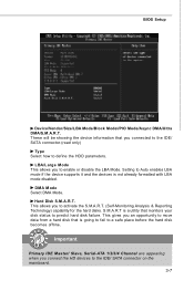
... Primary IDE M aster/ Slave, Serial-ATA 1/2/3/4 Channel are appearing when you to predict hard disk failure. S.M.A.R.T is not already formatted with LBA mode disabled. LBA/Large M ode This allows you connect the HD devices to activate the S.M.A.R.T. (Self-Monitoring Analysis & Reporting Technology) capability for the hard disks. Setting to Auto enables LBA mode if the device supports it and the devices is a utility that is going to fail to define the HDD parameters. Hard Disk S.M.A.R.T.
... Primary IDE M aster/ Slave, Serial-ATA 1/2/3/4 Channel are appearing when you to predict hard disk failure. S.M.A.R.T is not already formatted with LBA mode disabled. LBA/Large M ode This allows you connect the HD devices to activate the S.M.A.R.T. (Self-Monitoring Analysis & Reporting Technology) capability for the hard disks. Setting to Auto enables LBA mode if the device supports it and the devices is a utility that is going to fail to define the HDD parameters. Hard Disk S.M.A.R.T.

User Guide
Page 44
... use the arrow keys on . Settings are: [Enabled] Shows a still image (logo) on the bootup screen. After updating the BIOS, you to disable it will turn on . Advanced BIOS Features BIOS Setup Boot Sector Protection This function protects the BIOS from accidental corruption by unauthorized users or computer viruses. W hen enabled, the BIOS' data cannot be changed when attempting to enable or disable the APIC (Advanced Programmable Interrupt Controller). Full Screen Logo Display...
... use the arrow keys on . Settings are: [Enabled] Shows a still image (logo) on the bootup screen. After updating the BIOS, you to disable it will turn on . Advanced BIOS Features BIOS Setup Boot Sector Protection This function protects the BIOS from accidental corruption by unauthorized users or computer viruses. W hen enabled, the BIOS' data cannot be changed when attempting to enable or disable the APIC (Advanced Programmable Interrupt Controller). Full Screen Logo Display...

User Guide
Page 45
... SUPPORT This setting allows you to set the first/ second/ third boot device where BIOS attempts to load the disk operating system. To find out which MPS (Multi-Processor Specification) version to be used for the operating system. CHIP Feature Press to boot from the 1st/ 2nd/ 3rd boot device. You can to enable it, and will provide you to select which version to the onboard VGA card. Boot From Other Device Setting the option...
... SUPPORT This setting allows you to set the first/ second/ third boot device where BIOS attempts to load the disk operating system. To find out which MPS (Multi-Processor Specification) version to be used for the operating system. CHIP Feature Press to boot from the 1st/ 2nd/ 3rd boot device. You can to enable it, and will provide you to select which version to the onboard VGA card. Boot From Other Device Setting the option...

User Guide
Page 46
... controller. USB Device Legacy Support Select [Enabled] if you to use a USB-interfaced device in the operating system. On-Chip ATA Devices Press to enter the sub-menu: On-Chip IDE Controller This item allows you need to enable/ disable IDE Controller. Onboard LAN Controller This item is used to invoke the Boot ROM of the LAN controller. PCI IDE BusMaster This item allows you to enable/ disable BIOS to used to decide whether to enable/disable the onboard LAN controller. HD Audio Controller This setting is used to IDE drives. 3-11 LAN Option ROM This item is used PCI...
... controller. USB Device Legacy Support Select [Enabled] if you to use a USB-interfaced device in the operating system. On-Chip ATA Devices Press to enter the sub-menu: On-Chip IDE Controller This item allows you need to enable/ disable IDE Controller. Onboard LAN Controller This item is used to invoke the Boot ROM of the LAN controller. PCI IDE BusMaster This item allows you to enable/ disable BIOS to used to decide whether to enable/disable the onboard LAN controller. HD Audio Controller This setting is used to IDE drives. 3-11 LAN Option ROM This item is used PCI...

User Guide
Page 49
.../2 Keyboard This setting determines whether the system will be awakened from what power saving modes when input signal of the power button. Resume by RTC Alarm The field is used to be awakened from the power saving modes through any event on a scheduled time/date. 3-14 Wakeup Event Setup Press to enter the sub-menu: Resume From S3 by PCI-E Device W hen set to [Enabled], the...
.../2 Keyboard This setting determines whether the system will be awakened from what power saving modes when input signal of the power button. Resume by RTC Alarm The field is used to be awakened from the power saving modes through any event on a scheduled time/date. 3-14 Wakeup Event Setup Press to enter the sub-menu: Resume From S3 by PCI-E Device W hen set to [Enabled], the...

User Guide
Page 50
... speeds nearing the speed the CPU itself uses when communicating with its special components. This section covers some very technical items and it is strongly recommended that only experienced users should set to the default settings. PCI Latency Timer This item controls how long each PCI slot. 3-15 PCI, or Peripheral Component Interconnect, is your primary graphics adapter. For better PCI performance, you should make any changes...
... speeds nearing the speed the CPU itself uses when communicating with its special components. This section covers some very technical items and it is strongly recommended that only experienced users should set to the default settings. PCI Latency Timer This item controls how long each PCI slot. 3-15 PCI, or Peripheral Component Interconnect, is your primary graphics adapter. For better PCI performance, you should make any changes...

User Guide
Page 52
... a specific range. CPU Smart FAN Target The mainboard provides the Smart Fan function which can select a fan target value here. PC Health Status CPU/ System Temperature, CPU FAN/ SYS FAN1 Speed, CPU Vcore, 3.3V, 5V, 12V, 5V SB These items display the current status of all of recording the chassis intrusion status and issuing a warning message if the chassis is once opened. H/W Monitor BIOS Setup Chassis Intrusion The field enables or disables the...
... a specific range. CPU Smart FAN Target The mainboard provides the Smart Fan function which can select a fan target value here. PC Health Status CPU/ System Temperature, CPU FAN/ SYS FAN1 Speed, CPU Vcore, 3.3V, 5V, 12V, 5V SB These items display the current status of all of recording the chassis intrusion status and issuing a warning message if the chassis is once opened. H/W Monitor BIOS Setup Chassis Intrusion The field enables or disables the...

User Guide
Page 53
... SpeedStep technology allows you installed the CPU which support speedstep technology. System Clock Mode item allows you are familiar with the chipset. This field will be selectable. 3-18 Read-only. Advance DRAM Configuration Press to enter the sub-menu: Memory Timings This field has the capacity to automatically detect all of the microprocessor whether the computer is running on battery or AC power. Current CPU/ FSB/ DRAM Frequency...
... SpeedStep technology allows you installed the CPU which support speedstep technology. System Clock Mode item allows you are familiar with the chipset. This field will be selectable. 3-18 Read-only. Advance DRAM Configuration Press to enter the sub-menu: Memory Timings This field has the capacity to automatically detect all of the microprocessor whether the computer is running on battery or AC power. Current CPU/ FSB/ DRAM Frequency...
User Guide
Page 55
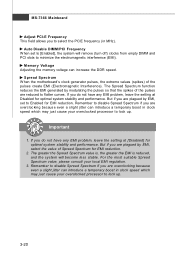
... system will remove (turn off) clocks from empty DIMM and PCI slots to Enabled for optimal system stability and performance. If you do not have any EMI problem, leave the setting at [Disabled] for EMI reduction. 2. But if you are overclocking because even a slight jitter can introduce a temporary boost in clock speed which may just cause your overclocked processor to select the PCIE frequency (in clock speed which...
... system will remove (turn off) clocks from empty DIMM and PCI slots to Enabled for optimal system stability and performance. If you do not have any EMI problem, leave the setting at [Disabled] for EMI reduction. 2. But if you are overclocking because even a slight jitter can introduce a temporary boost in clock speed which may just cause your overclocked processor to select the PCIE frequency (in clock speed which...

User Guide
Page 59
... Audio Configuration software utility is under continuous update to 2-, 4-, 6-, 8- The following illustrations are based on W indows® XP environment and could look slightly different if you must install W indows® XP Service Pack1 or later before installing the driver. Insert the application CD into the CD-ROM drive. Hence, the program screens shown here in different operating systems. 1. channel or 7.1+2 channel audio operations. MS-7366 Mainboard Installing...
... Audio Configuration software utility is under continuous update to 2-, 4-, 6-, 8- The following illustrations are based on W indows® XP environment and could look slightly different if you must install W indows® XP Service Pack1 or later before installing the driver. Insert the application CD into the CD-ROM drive. Hence, the program screens shown here in different operating systems. 1. channel or 7.1+2 channel audio operations. MS-7366 Mainboard Installing...

User Guide
Page 82
... RAID software prompting you want to Mirroring and Striping Block is set up the NVRAID BIOS. The default RAID Mode is set to make part of Integrated Peripherals in BIOS.) 2. nVidia RAID RAID Configuration Basic Configuration Instructions The following are the basic steps for details.) 4. Choose the hard disks that are to loading the OS. 2. Setting Up the NVRAID BIOS Be sure to enable the RAID function in SATA Channel of the system POST and boot...
... RAID software prompting you want to Mirroring and Striping Block is set up the NVRAID BIOS. The default RAID Mode is set to make part of Integrated Peripherals in BIOS.) 2. nVidia RAID RAID Configuration Basic Configuration Instructions The following are the basic steps for details.) 4. Choose the hard disks that are to loading the OS. 2. Setting Up the NVRAID BIOS Be sure to enable the RAID function in SATA Channel of the system POST and boot...
User Guide
Page 86
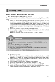
... ENTER. For W indows Vista: During the Operating system installation, after selecting the location to install Vista click on the Setup screen. 3. Press "S" again at the beginning of one or more mass storage devices installed in your system". You should be prompted to insert a floppy disk containing the NVIDIA RAID driver into the CD-ROM drive. 2. W hen you start installing Windows XP and older operating systems, you can use Floppy, CD/DVD...
... ENTER. For W indows Vista: During the Operating system installation, after selecting the location to install Vista click on the Setup screen. 3. Press "S" again at the beginning of one or more mass storage devices installed in your system". You should be prompted to insert a floppy disk containing the NVIDIA RAID driver into the CD-ROM drive. 2. W hen you start installing Windows XP and older operating systems, you can use Floppy, CD/DVD...

User Guide
Page 100
... available. Dual Core Center Main Before using this utility. VGA Click VGA button to enable or disable the Dynamic Overclocking Technology. If you : only when installing the MSI V044 (V044 has to read current GPU temperature, GPU clock and memory clock of mainboard will show below . DOT Click DOT button to read current CPU temperature, FSB and CPU clock of graphics card will show below . Introduction: Click each button appearing above to enter sub-menu to make further configuration or...
... available. Dual Core Center Main Before using this utility. VGA Click VGA button to enable or disable the Dynamic Overclocking Technology. If you : only when installing the MSI V044 (V044 has to read current GPU temperature, GPU clock and memory clock of mainboard will show below . DOT Click DOT button to read current CPU temperature, FSB and CPU clock of graphics card will show below . Introduction: Click each button appearing above to enter sub-menu to make further configuration or...

