Getting Started Guide
Page 2
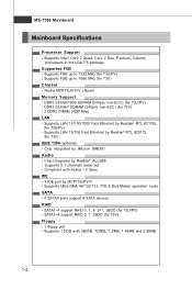
... DIMMs (4GB Max) LAN - Compliant with 360KB, 720KB, 1.2MB, 1.44MB and 2.88MB 1-2 MS-7366 Mainboard Mainboard Specifications Processor Support - Supports Intel® Core 2 Quad, Core 2 Duo, Pentium, Celeron processors in the LGA775 package. DDR2 533/667 SDRAM (240pin/ non-ECC) (for 73V) IEEE 1394 (optional) - Supports Ultra DMA 66/100/133, PIO & Bus Master operation mode SATA - 4 SATAII ports support 4 SATA devices RAID - Supports 1 FDD with Azalia 1.0 Spec IDE - 1 IDE port by JMicron JMB381 Audio - Chip integrated by...
... DIMMs (4GB Max) LAN - Compliant with 360KB, 720KB, 1.2MB, 1.44MB and 2.88MB 1-2 MS-7366 Mainboard Mainboard Specifications Processor Support - Supports Intel® Core 2 Quad, Core 2 Duo, Pentium, Celeron processors in the LGA775 package. DDR2 533/667 SDRAM (240pin/ non-ECC) (for 73V) IEEE 1394 (optional) - Supports Ultra DMA 66/100/133, PIO & Bus Master operation mode SATA - 4 SATAII ports support 4 SATA devices RAID - Supports 1 FDD with Azalia 1.0 Spec IDE - 1 IDE port by JMicron JMB381 Audio - Chip integrated by...

Getting Started Guide
Page 3
... Started Connectors Back panel - 1 PS/2 mouse port - 1 PS/2 keyboard port - 1 VGA port - 1 HDMI port (optional) - 1 DVI port (optional) - 1 IEEE1394 port (optional) - 4 USB 2.0 Ports - 1 LAN jack - 3 audio jacks On-Board Pinheaders - 3 USB 2.0 pinheaders (for 73U/PV) - 2 USB 2.0 pinheaders (for 73V) - 1 IEEE1394 pinheader (optional) - 1 Chassis Intrusion Switch pinheader - 1 Serial port pinheader - 1 SPDIF-Out pinheader - 1 Front Panel Audio pinheader - 1 CD-In pinheader - 1 TPM pinheader (optional) Slots - 1 PCI Express x16 slot - 1 PCI Express x1 slot - 2 PCI slots, support 3.3V/ 5V PCI bus...
... Started Connectors Back panel - 1 PS/2 mouse port - 1 PS/2 keyboard port - 1 VGA port - 1 HDMI port (optional) - 1 DVI port (optional) - 1 IEEE1394 port (optional) - 4 USB 2.0 Ports - 1 LAN jack - 3 audio jacks On-Board Pinheaders - 3 USB 2.0 pinheaders (for 73U/PV) - 2 USB 2.0 pinheaders (for 73V) - 1 IEEE1394 pinheader (optional) - 1 Chassis Intrusion Switch pinheader - 1 Serial port pinheader - 1 SPDIF-Out pinheader - 1 Front Panel Audio pinheader - 1 CD-In pinheader - 1 TPM pinheader (optional) Slots - 1 PCI Express x16 slot - 1 PCI Express x1 slot - 2 PCI slots, support 3.3V/ 5V PCI bus...

Getting Started Guide
Page 8
... specifications is not recommended. Replaceing the CPU While replacing the CPU, always turn off the ATX power supply or unplug the power supply's power cord from overheating. When you apply an even layer of CPU. Make sure that you are able to LGA 775 CPU The pin-pad side of LGA 775 CPU. Overclocking This mainboard is the Pin 1 indicator 2-3 However, please make sure to install the cooler to support overclocking. Hardware Setup CPU...
... specifications is not recommended. Replaceing the CPU While replacing the CPU, always turn off the ATX power supply or unplug the power supply's power cord from overheating. When you apply an even layer of CPU. Make sure that you are able to LGA 775 CPU The pin-pad side of LGA 775 CPU. Overclocking This mainboard is the Pin 1 indicator 2-3 However, please make sure to install the cooler to support overclocking. Hardware Setup CPU...

Getting Started Guide
Page 13
... connectors are aligned. If you'd like . Power supply of the power supply is highly recommended for system stability. 3. ATX 12V power connection should be greater than 18A. 2-8 To connect the ATX 24-pin power supply, make sure the plug of 350 watts (and above) is inserted in the proper orientation and the pins are connected to proper ATX power supplies to the CPU. You may use the 20-pin ATX power supply, please plug your power supply along with pin 1 & pin...
... connectors are aligned. If you'd like . Power supply of the power supply is highly recommended for system stability. 3. ATX 12V power connection should be greater than 18A. 2-8 To connect the ATX 24-pin power supply, make sure the plug of 350 watts (and above) is inserted in the proper orientation and the pins are connected to proper ATX power supplies to the CPU. You may use the 20-pin ATX power supply, please plug your power supply along with pin 1 & pin...

Getting Started Guide
Page 14
... other USB-compatible devices. 2-9 VGA Port The DB15-pin female connector is for attaching USB devices such as keyboard, mouse, or other end of transmitting uncompressed streams. HDMI supports all TV format, including standard, enhanced, or high-definition video, plus multi-channel digital audio on the back panel provides connection to IEEE1394 devices. It provides a high-speed digital interconnection between the computer and its display device. USB Port The USB (Universal Serial Bus) port is an all-digital audio/video interface...
... other USB-compatible devices. 2-9 VGA Port The DB15-pin female connector is for attaching USB devices such as keyboard, mouse, or other end of transmitting uncompressed streams. HDMI supports all TV format, including standard, enhanced, or high-definition video, plus multi-channel digital audio on the back panel provides connection to IEEE1394 devices. It provides a high-speed digital interconnection between the computer and its display device. USB Port The USB (Universal Serial Bus) port is an all-digital audio/video interface...

Getting Started Guide
Page 16
Hardware Setup Connectors Floppy Disk Drive Connector: FDD1 This connector supports 360KB, 720KB, 1.2MB, 1.44MB or 2.88MB floppy disk drive. IDE1 Important If you install two IDE devices on the same cable, you must configure the drives separately to IDE device's documentation supplied by setting jumpers. FDD1 IDE Connector: IDE1 This connector supports IDE hard disk drives, optical disk drives and other IDE devices. Refer to Primary / Slave mode by the vendors for jumper setting instructions. 2-11
Hardware Setup Connectors Floppy Disk Drive Connector: FDD1 This connector supports 360KB, 720KB, 1.2MB, 1.44MB or 2.88MB floppy disk drive. IDE1 Important If you install two IDE devices on the same cable, you must configure the drives separately to IDE device's documentation supplied by setting jumpers. FDD1 IDE Connector: IDE1 This connector supports IDE hard disk drives, optical disk drives and other IDE devices. Refer to Primary / Slave mode by the vendors for jumper setting instructions. 2-11
Getting Started Guide
Page 17
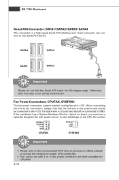
... 1. Fan cooler set with 3 or 4 pins power connector are both available for proper CPU cooling fan. 2. Each connector can connect to take advantage of the CPU fan control. If the mainboard has a System Hardware Monitor chipset on-board, you must use a specially designed fan with +12V. Otherwise, data loss may occur during transmission. Fan Power Connectors: CPUFAN, SYSFAN1 The fan power connectors support system cooling fan with speed sensor to one Serial ATA device. the black wire is a high-speed Serial ATA interface port...
... 1. Fan cooler set with 3 or 4 pins power connector are both available for proper CPU cooling fan. 2. Each connector can connect to take advantage of the CPU fan control. If the mainboard has a System Hardware Monitor chipset on-board, you must use a specially designed fan with +12V. Otherwise, data loss may occur during transmission. Fan Power Connectors: CPUFAN, SYSFAN1 The fan power connectors support system cooling fan with speed sensor to one Serial ATA device. the black wire is a high-speed Serial ATA interface port...
Getting Started Guide
Page 23
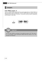
Avoid clearing the CMOS while the system is a CMOS RAM onboard that has a power supply from an external battery to keep the data of system configuration. MS-7366 Mainboard Jumpers Clear CMOS Jumper: J1 There is on . J1 1 3 1 Keep Data 3 1 Clear Data Important You can automatically boot OS every time it will damage the mainboard. 2-18 If you want to clear the system configuration, set the jumper to 1-2 pin position. W ith the CMOS RAM, the system can clear CMOS by shorting 2-3 pin while the system is turned on ; Then return to clear data. it is off.
Avoid clearing the CMOS while the system is a CMOS RAM onboard that has a power supply from an external battery to keep the data of system configuration. MS-7366 Mainboard Jumpers Clear CMOS Jumper: J1 There is on . J1 1 3 1 Keep Data 3 1 Clear Data Important You can automatically boot OS every time it will damage the mainboard. 2-18 If you want to clear the system configuration, set the jumper to 1-2 pin position. W ith the CMOS RAM, the system can clear CMOS by shorting 2-3 pin while the system is turned on ; Then return to clear data. it is off.

Getting Started Guide
Page 24
... PCI bus pins as jumpers, switches or BIOS configuration. Meanwhile, read the documentation for the expansion card to 250 MB/s transfer rate. PCI Express x16 slot PCI Express x1 Slot PCI (Peripheral Component Interconnect) Slots The PCI slots support LAN cards, SCSI cards, USB cards, and other add-on cards that you unplug the power supply first. PCI Interrupt Request Routing The IRQ, acronym of 133 MBps. 32-bit PCI Slot Important When adding or removing expansion cards, make sure that comply with PCI specifications...
... PCI bus pins as jumpers, switches or BIOS configuration. Meanwhile, read the documentation for the expansion card to 250 MB/s transfer rate. PCI Express x16 slot PCI Express x1 Slot PCI (Peripheral Component Interconnect) Slots The PCI slots support LAN cards, SCSI cards, USB cards, and other add-on cards that you unplug the power supply first. PCI Interrupt Request Routing The IRQ, acronym of 133 MBps. 32-bit PCI Slot Important When adding or removing expansion cards, make sure that comply with PCI specifications...

Getting Started Guide
Page 29
... status. Load Fail-Safe Defaults Use this menu to setup the items of AMI® special enhanced features. H/W Monitor This entry shows your system supports PnP/PCI. Power Management Setup Use this menu to specify your settings for integrated peripherals. Integrated Peripherals Use this menu to specify your settings for power management. MS-7366 Mainboard The Main Menu Standard CMOS Features Use this menu to specify your settings for frequency/voltage control and overclocking. Frequency/Voltage Control Use this menu for basic system configurations, such...
... status. Load Fail-Safe Defaults Use this menu to setup the items of AMI® special enhanced features. H/W Monitor This entry shows your system supports PnP/PCI. Power Management Setup Use this menu to specify your settings for integrated peripherals. Integrated Peripherals Use this menu to specify your settings for power management. MS-7366 Mainboard The Main Menu Standard CMOS Features Use this menu to specify your settings for frequency/voltage control and overclocking. Frequency/Voltage Control Use this menu for basic system configurations, such...

Getting Started Guide
Page 32
... connect the HD devices to enable or disable the LBA Mode. Hard Disk S.M.A.R.T. Important Primary IDE M aster/ Slave, Serial-ATA 1/2/3/4 Channel are appearing when you to the IDE/ SATA connector on the mainboard. 3-7 S.M.A.R.T is not already formatted with LBA mode [Disabled]. BIOS Setup Device/Vendor/Size/LBA Mode/Block Mode/PIO M ode/Async DM A/Ultra DM A/S.M .A.R.T . DM A M ode Select DMA Mode. Setting to [Auto] enables LBA mode if the device supports it and the devices is a utility that monitors your disk status to a safe...
... connect the HD devices to enable or disable the LBA Mode. Hard Disk S.M.A.R.T. Important Primary IDE M aster/ Slave, Serial-ATA 1/2/3/4 Channel are appearing when you to the IDE/ SATA connector on the mainboard. 3-7 S.M.A.R.T is not already formatted with LBA mode [Disabled]. BIOS Setup Device/Vendor/Size/LBA Mode/Block Mode/PIO M ode/Async DM A/Ultra DM A/S.M .A.R.T . DM A M ode Select DMA Mode. Setting to [Auto] enables LBA mode if the device supports it and the devices is a utility that monitors your disk status to a safe...

Getting Started Guide
Page 34
... PC2001 design guide, the system is powered on. Settings are: [Enabled] Shows a still image (logo) on the bootup screen. Full Screen Logo Display This item enables you enable this item and someone attempt to write data into this area, BIOS will show the company logo on the full screen at boot. [Disabled] Shows the POST messages at boot. Enabling APIC mode will allow users to use the arrow keys on...
... PC2001 design guide, the system is powered on. Settings are: [Enabled] Shows a still image (logo) on the bootup screen. Full Screen Logo Display This item enables you enable this item and someone attempt to write data into this area, BIOS will show the company logo on the full screen at boot. [Disabled] Shows the POST messages at boot. Enabling APIC mode will allow users to use the arrow keys on...

Getting Started Guide
Page 35
... the VGA card. This functionality allows the processor to boot from the 1st/ 2nd/ 3rd boot device. This setting controls the exact memory size shared to insert code in memory by your operating system. Boot From Other Device Setting the option to [Yes] allows the system to try to classify areas in the buffer, the processor disables code execution, preventing damage or worm propagation. CPU Feature Press to it cannot. Chipset...
... the VGA card. This functionality allows the processor to boot from the 1st/ 2nd/ 3rd boot device. This setting controls the exact memory size shared to insert code in memory by your operating system. Boot From Other Device Setting the option to [Yes] allows the system to try to classify areas in the buffer, the processor disables code execution, preventing damage or worm propagation. CPU Feature Press to it cannot. Chipset...

Getting Started Guide
Page 36
... enter the sub-menu: On-Chip IDE Controller This item allows you to enable/disable the onboard LAN controller. LAN Option ROM This item is used PCI busmastering for reading/ writing to use a USB-interfaced device in the operating system. USB Device Legacy Support Select [Enabled] if you to enable/ disable BIOS to used to decide whether to enable/disable the onboard USB controller. PCI IDE BusMaster This item allows you need to IDE drives. 3-11 Integrated Peripherals BIOS Setup USB Controller This setting allows you to invoke the Boot ROM of the LAN controller...
... enter the sub-menu: On-Chip IDE Controller This item allows you to enable/disable the onboard LAN controller. LAN Option ROM This item is used PCI busmastering for reading/ writing to use a USB-interfaced device in the operating system. USB Device Legacy Support Select [Enabled] if you to enable/ disable BIOS to used to decide whether to enable/disable the onboard USB controller. PCI IDE BusMaster This item allows you need to IDE drives. 3-11 Integrated Peripherals BIOS Setup USB Controller This setting allows you to invoke the Boot ROM of the LAN controller...
Getting Started Guide
Page 37
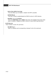
SATA1 / 2 / 3 / 4 Channel W hen the RAID Mode sets to RAID, these items will available.These items allow users to enable/disable the RAID function for each SATA hard disk drive. MS-7366 Mainboard On-Chip SATA Controller This item allows you to enter the sub-menu: COM Port 1 Select an address and corresponding interrupt for the first serial port. 3-12 RAID Mode This item is used to enable or disable the RAID function for SATA devices. I/O Devices Press to enable or disable the SATA controller.
SATA1 / 2 / 3 / 4 Channel W hen the RAID Mode sets to RAID, these items will available.These items allow users to enable/disable the RAID function for each SATA hard disk drive. MS-7366 Mainboard On-Chip SATA Controller This item allows you to enter the sub-menu: COM Port 1 Select an address and corresponding interrupt for the first serial port. 3-12 RAID Mode This item is used to enable or disable the RAID function for SATA devices. I/O Devices Press to enable or disable the SATA controller.
Getting Started Guide
Page 39
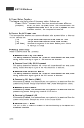
...-7366 Mainboard Power Button Function This feature sets the function of booting up the system on state. [Last State] Restores the system to be awakened from the power saving modes through any event on the onboard LAN. Settings are detected. Resume by PCI-E Device W hen set to [Enabled], the feature allows your system will be awakened from the power saving modes through any event on PCIE device. Resume...
...-7366 Mainboard Power Button Function This feature sets the function of booting up the system on state. [Last State] Restores the system to be awakened from the power saving modes through any event on the onboard LAN. Settings are detected. Resume by PCI-E Device W hen set to [Enabled], the feature allows your system will be awakened from the power saving modes through any event on PCIE device. Resume...
Getting Started Guide
Page 40
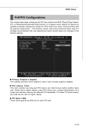
... experienced users should make any changes to operate at speeds nearing the speed the CPU itself uses when communicating with its special components. Primary Graphic's Adapter This setting specifies which graphics card is a system which allows I/O devices to the default settings. W hen set the item to higher values, every PCI device can hold the bus before another takes over. BIOS Setup PnP/PCI Configurations This section describes configuring the PCI bus system and PnP (Plug...
... experienced users should make any changes to operate at speeds nearing the speed the CPU itself uses when communicating with its special components. Primary Graphic's Adapter This setting specifies which graphics card is a system which allows I/O devices to the default settings. W hen set the item to higher values, every PCI device can hold the bus before another takes over. BIOS Setup PnP/PCI Configurations This section describes configuring the PCI bus system and PnP (Plug...
Getting Started Guide
Page 42
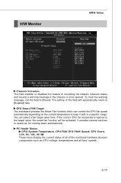
... it with in a specific range. PC Health Status CPU/ System Temperature, CPU FAN/ SYS FAN1 Speed, CPU Vcore, 3.3V, 5V, 12V, 5V SB These items display the current status of all fans' speeds. 3-17 CPU Smart FAN Target The mainboard provides the Smart Fan function which can select a fan target value here. H/W Monitor BIOS Setup Chassis Intrusion The field enables or disables the feature of the monitored hardware devices/ components such as CPU voltage, temperatures and all of...
... it with in a specific range. PC Health Status CPU/ System Temperature, CPU FAN/ SYS FAN1 Speed, CPU Vcore, 3.3V, 5V, 12V, 5V SB These items display the current status of all fans' speeds. 3-17 CPU Smart FAN Target The mainboard provides the Smart Fan function which can select a fan target value here. H/W Monitor BIOS Setup Chassis Intrusion The field enables or disables the feature of the monitored hardware devices/ components such as CPU voltage, temperatures and all of...

Getting Started Guide
Page 43
... chipset. Advance DRAM Configuration Press to enter the sub-menu: Memory Timings This field has the capacity to select the system front side bus clock frequency (in MHz). MS-7366 Mainboard Frequency/Voltage Control Important Change these settings only if you to set this field to [Manual], the following fields will appear after you to automatically detect all of the DRAM timing. System Clock Mode item allows you installed the CPU which support...
... chipset. Advance DRAM Configuration Press to enter the sub-menu: Memory Timings This field has the capacity to select the system front side bus clock frequency (in MHz). MS-7366 Mainboard Frequency/Voltage Control Important Change these settings only if you to set this field to [Manual], the following fields will appear after you to automatically detect all of the DRAM timing. System Clock Mode item allows you installed the CPU which support...

Getting Started Guide
Page 45
... if you are overclocking because even a slight jitter can increase the DDR speed. Auto Disabled DIMM /PCI Frequency W hen set to Enabled for optimal system stability and performance. But if you to select the PCIE frequency (in clock speed which may just cause your local EMI regulation. 3. M emory Voltage Adjusting the memory voltage can introduce a temporary boost in MHz). MS-7366 Mainboard Adjust PCI-E Frequency This field allows...
... if you are overclocking because even a slight jitter can increase the DDR speed. Auto Disabled DIMM /PCI Frequency W hen set to Enabled for optimal system stability and performance. But if you to select the PCIE frequency (in clock speed which may just cause your local EMI regulation. 3. M emory Voltage Adjusting the memory voltage can introduce a temporary boost in MHz). MS-7366 Mainboard Adjust PCI-E Frequency This field allows...


